Tentang proyek ini
Lihat situs saya untuk jam ini Situs Jam Arduino DCF77 Analyzerhttp://www.brettoliver.org.uk/DCF77_Analyzer_Clock_Mk2/Arduino_DCF77_Analyzer_MK2.htm
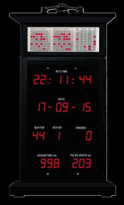
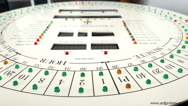
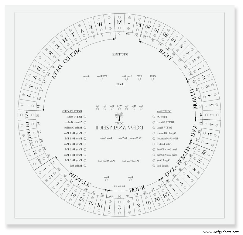
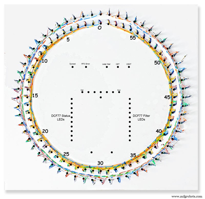
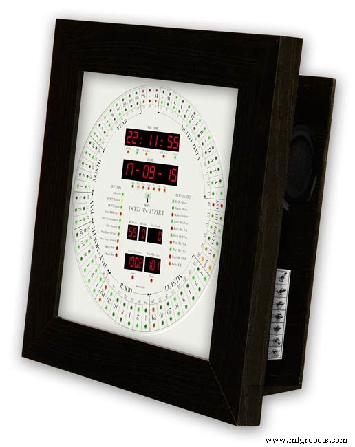
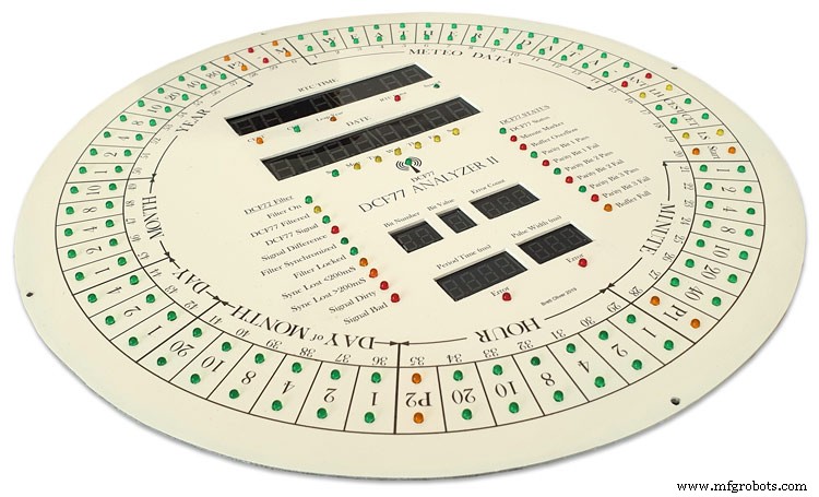
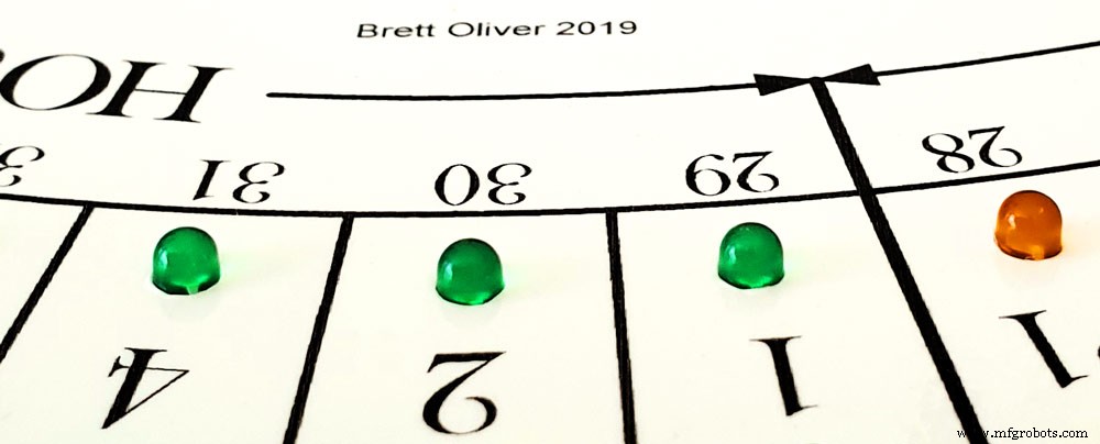
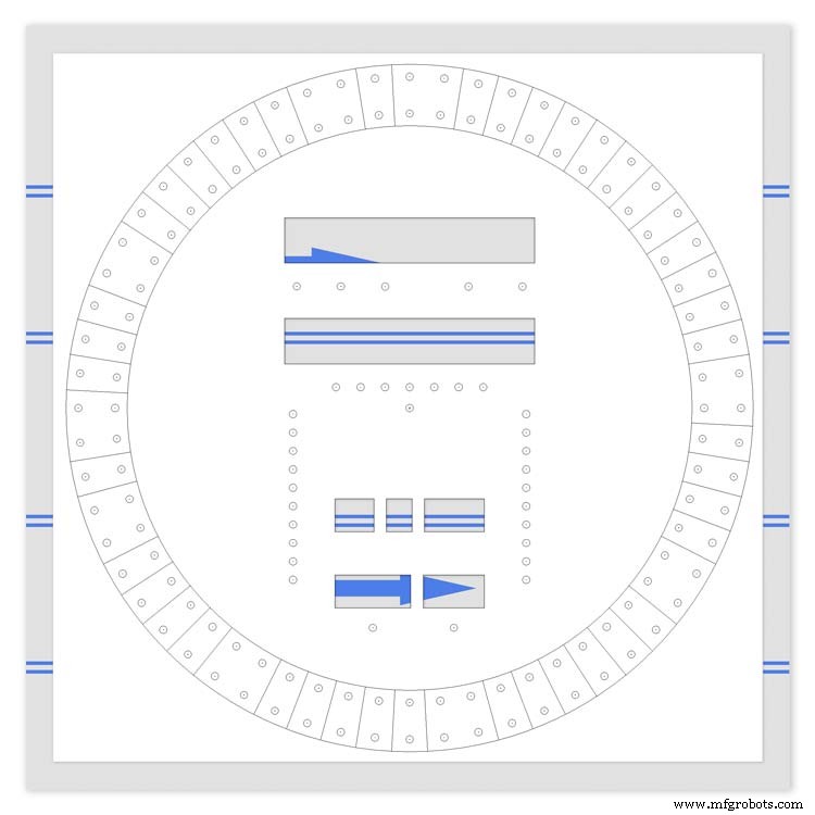
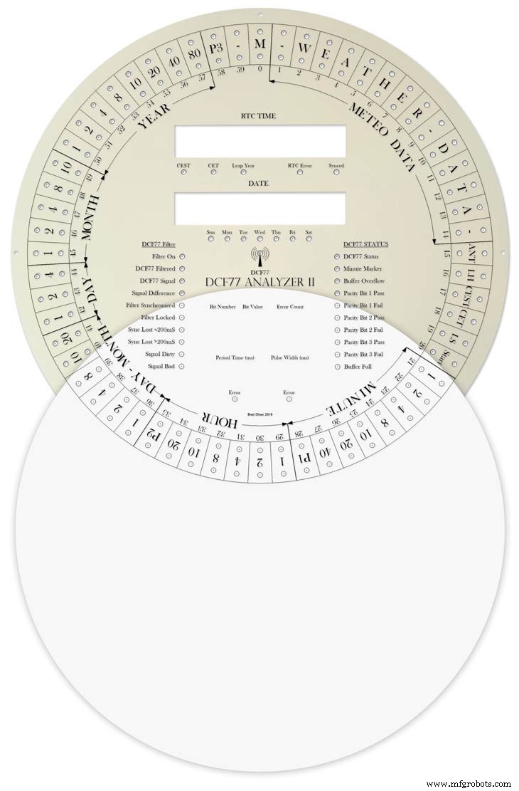
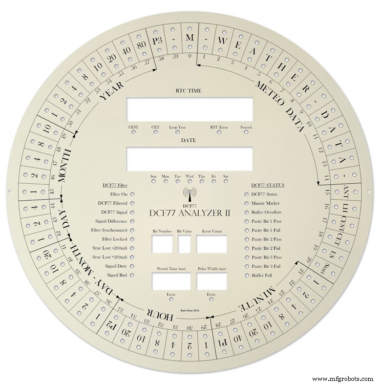
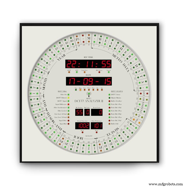
Jam ini menampilkan kode waktu DCF77 pada 2 cincin 60 LED pada dial besar berdiameter 12" (305mm). Cincin bagian dalam menunjukkan kode waktu langsung untuk menit berikutnya saat diterima dan cincin luar menunjukkan waktu saat ini selama karena menit sebelumnya diterima tanpa kesalahan.
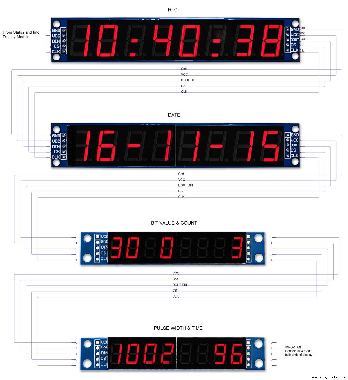
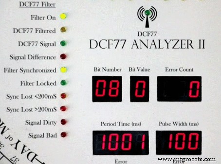
Selanjutnya 24 LED menunjukkan status decoder dan info waktu. Waktu dan tanggal yang didekode ditampilkan pada 2 tampilan besar 8 digit 7 segmen sementara waktu pulsa DCF77 dan informasi bit ditampilkan pada 2 tampilan segmen 7 8 digit lebih kecil.
Jam menggunakan 2 x mikroprosesor Atmega 328 (Arduino Uno), 1 untuk mengontrol DCF77 Analyzer dan 1 untuk mengontrol Udo Klein Super Filter. Filter Super memungkinkan pemrosesan sinyal DCF77 tingkat lanjut dan juga penyetelan kristal kuarsa Arduino. Filter dapat dialihkan dan memiliki 10 LED status untuk menunjukkan status penerimaan sinyal dan kualitas keluaran. Jam juga membunyikan jam, seperempat jam, dan detik melalui 2 modul suara JQ6500.
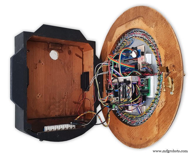
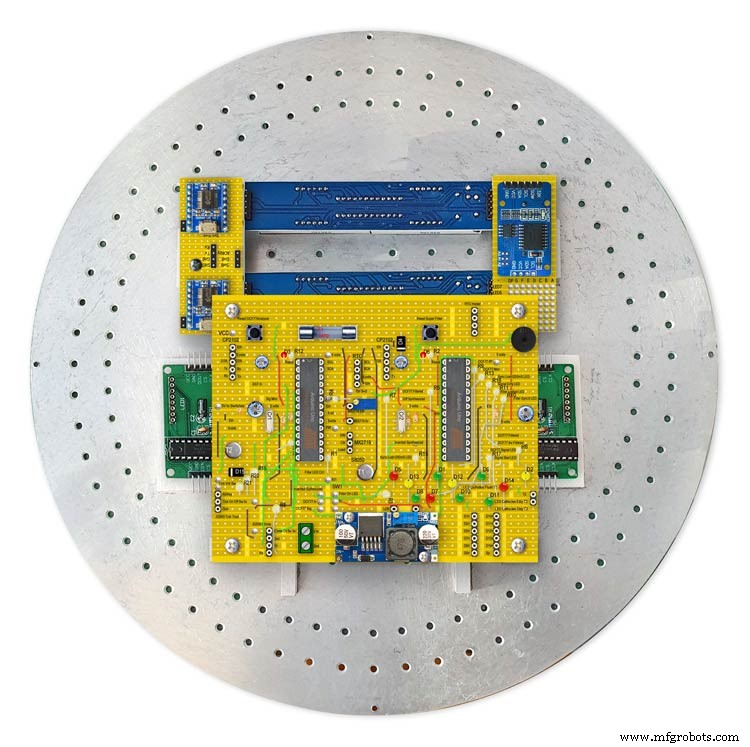
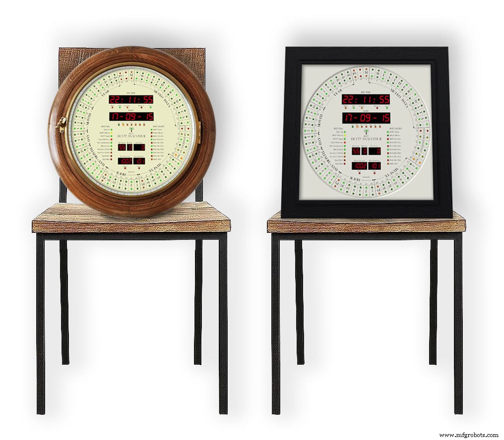
Sebagian besar elektronik dipasang di bagian belakang dial sehingga jam dapat dipasang ke berbagai gaya casing.
Saya telah menyertakan desain untuk kotak jam bergaya retro dan modern. desain retro dipasang pada kotak jam tua, sedangkan desain modern dipasang pada bingkai foto hitam.
Langkah 1:Kredit
Jam ini didasarkan pada Jam Penganalisis DCF77 oleh Erik de Ruiter dan merupakan versi terbaru dari jam Penganalisis DCF77 Mk1 saya.
di atas Jam Penganalisis DCF77 Erik de Ruiter di bawah jam penganalisis DCF77 MK1 saya.
Erik telah memberikan detail lengkap jamnya di GitHub
Perbedaan antara Jam Eric dan jam saya
Meskipun berdasarkan jam Eric saya telah membuat beberapa perubahan pada perangkat keras. Silakan campur dan cocokkan opsi apa pun yang sesuai dengan kebutuhan Anda, tetapi pastikan Anda mengubah kode yang sesuai.
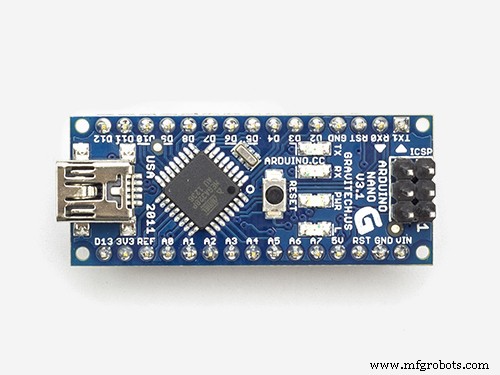
Saya menggunakan dua Arduino UNo yang dibuat khusus di Veroboard daripada Uno dan Mega.
Saya menggunakan tampilan 7 segmen murah dan modul dot matrix dari seluruh China dan telah mengubah kode agar sesuai. Lihat bagian tentang kesalahan tampilan karena berfungsi dengan sangat baik setelah mod ini dilakukan.
Saya menggunakan 2x modul JQ6500 daripada papan suara Adafruit. Karena salah satu papan saya dikendalikan oleh perangkat lunak, ada beberapa perubahan perangkat lunak dan perpustakaan lain untuk dimuat.
Karena saya memiliki Arduino Uno alih-alih Arduino Mega, saya tidak memiliki semua pin cadangan untuk menggerakkan LED decoder, jadi saya menggunakan modul dot matrix ke-3 sebagai gantinya.
Saya telah memodifikasi Filter Super Udo Klein dengan menambahkan LED status tambahan. Kecerahan LED ini adalah PWM yang dikendalikan oleh decoder DCF77 Uno melalui 2 transistor bukan Super Filter Uno.
Ada juga fungsi uji LED yang ditambahkan ke Filter Super agar sesuai dengan fungsi uji dekoder DCF77.
Saya hanya menggunakan LED 3mm dan telah memilih LED kecerahan yang cocok untuk mencoba dan menjaga kecerahan seragam.
Saya telah menambahkan 4 tingkat intensitas terpisah dalam perangkat lunak sehingga LED Ring/Status, tampilan 7 segmen besar, tampilan 7 segmen kecil, dan LED Filter Super semuanya memiliki tingkat kecerahan khusus tergantung pada pembacaan dari LDR tunggal.
Saya tidak memiliki tampilan suhu atau angka minggu pada jam saya dan telah memodifikasi kode yang sesuai.
Saya telah menambahkan LED monitor ekstra ke Filter Super saya sehingga pada jam saya hanya ada opsi untuk output Sythesized dan Non Sythesized. Ini bukan pilihan untuk beralih mode sesuai jam Erik.
Suara DCF77 pada jam saya telah dimodifikasi untuk menonjolkan perbedaan antara 0 dan 1 yang masuk. Saat jam mendeteksi angka 1, jam hanya memainkan suara yang sedikit lebih panjang dari 200mS.
Langkah 2:Video
Video menunjukkan jam berjalan dengan suara centang menyala dan juga jam berbunyi seperempat dan jam penuh.
Ini juga menunjukkan tata letak dial dan informasi tentang membaca tampilan.
Video 2
Video yang menunjukkan pengaktifan, uji tampilan, dan dekode waktu/tanggal
Video 3
Video yang menunjukkan cara kerja filter Udo Klein Super pada jam ini
Video 4
Video menunjukkan jam bingkai foto berjalan dengan suara centang menyala dan juga jam berbunyi seperempat dan jam penuh.
Ini juga menunjukkan tata letak dial dan informasi tentang membaca tampilan.
Video 5
Video singkat ini menunjukkan jam penganalisis DCF77 saya yang menampilkan dan mendekode sinyal DCF77. Semua suara di luar batas sinyal langsung DCF77.
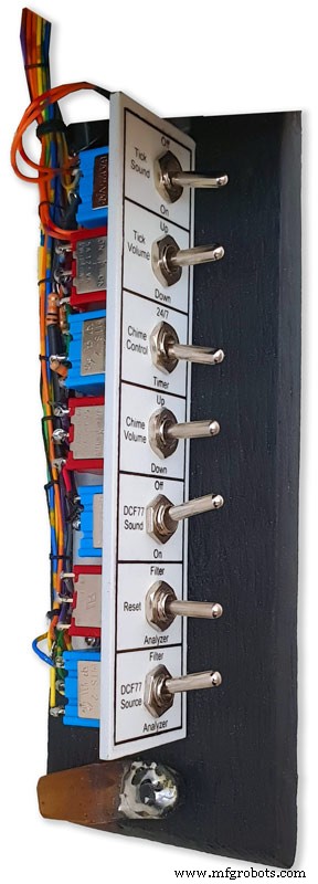
Langkah 3:Kontrol 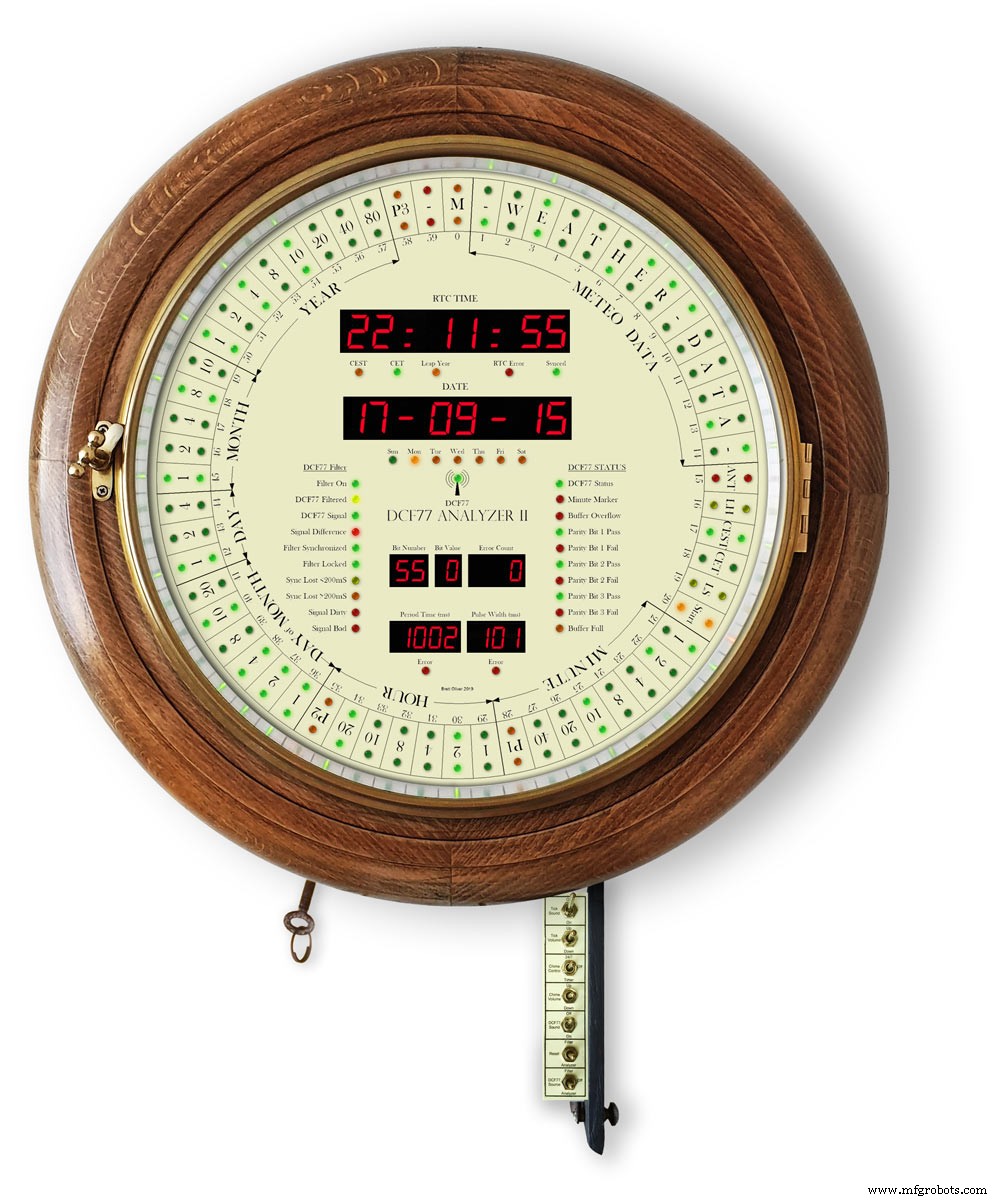
Jam dikendalikan oleh 7 sakelar yang dipasang pada batang logam. Sakelar terpasang ke bagian dalam pintu berengsel yang terlipat di bawah jam untuk akses.
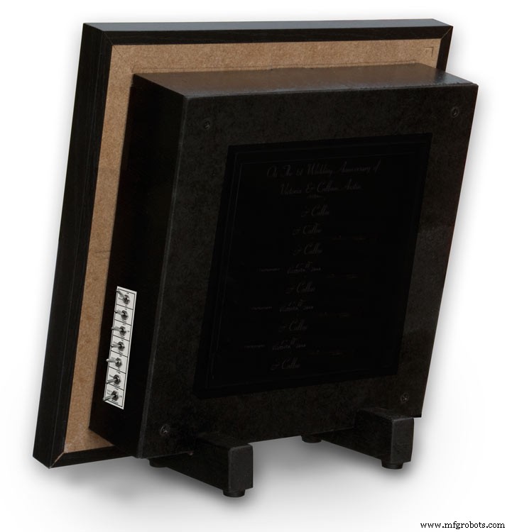
Pada versi bingkai foto, sakelar dipasang ke lubang di sisi jam.
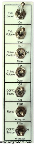
Sakelar mengontrol yang berikut
Suara centang On/Off
Centang Volume
Berpadu 24/7 atau pengatur waktu
Volume Lonceng
Suara DCF77 Nyala/Mati
Setel ulang Super filter atau Penganalisis
Sumber DCF77 dari Filter, Nonaktif, atau Penganalisis
Beralih Fungsi
Suara Centang
Mengaktifkan dan menonaktifkan suara tik tok (menghilangkan daya dari modul JQ6500)
Centang Volume tidak terkunci
Mengangkat dan menurunkan volume tik tok (Switch suara tik harus Aktif)
Kontrol Lonceng
Lonceng mati dimatikan
Lonceng 24/7 menyala 24/7
Lonceng pengatur waktu hanya menyala pada waktu yang ditentukan dalam sehari, mis. off di malam hari
Volume Lonceng tidak terkunci
Naikkan volume
Turunkan volume turun
Setelah setiap tombol ditekan, lonceng percobaan dimainkan sehingga Anda dapat mendengar pengaturan volume baru
Suara DCF77
Aktif memainkan suara DCF77 yang diterima sebagai bip melalui sounder Piezoelektrik.
0 menjadi 100mS dan 1 dimainkan sebagai bunyi bip 500mS untuk memudahkan membedakan 0 &1 yang diterima.
Mati suara bip DCF77 Mati
Setel ulang tanpa penguncian
Filter menyetel ulang Filter Super DCF77 sehingga membuatnya disinkronkan ulang ke sinyal DCF77
Penganalisis mengatur ulang Penganalisis DCF77 dimulai dengan uji tampilan jika diaktifkan dan kemudian sinkronisasi ulang jam. Waktu RTC akan ditampilkan dari waktu yang disimpan dalam jam waktu nyata
Sumber DCF77
Off memutuskan sinyal DCF77 dari jam
Penganalisis sinyal DCF77 diumpankan langsung ke jam tanpa pemfilteran apa pun
Filter sinyal DCF77 diambil dari Filter Super dan jika Filter Super disinkronkan, sinyal ini disintesis menjadi sinyal bebas kesalahan yang benar
Langkah 4:Skema
Ada 3 skema untuk jam ini. Papan utama, modul dot matrix, dan modul tampilan 7 segmen.
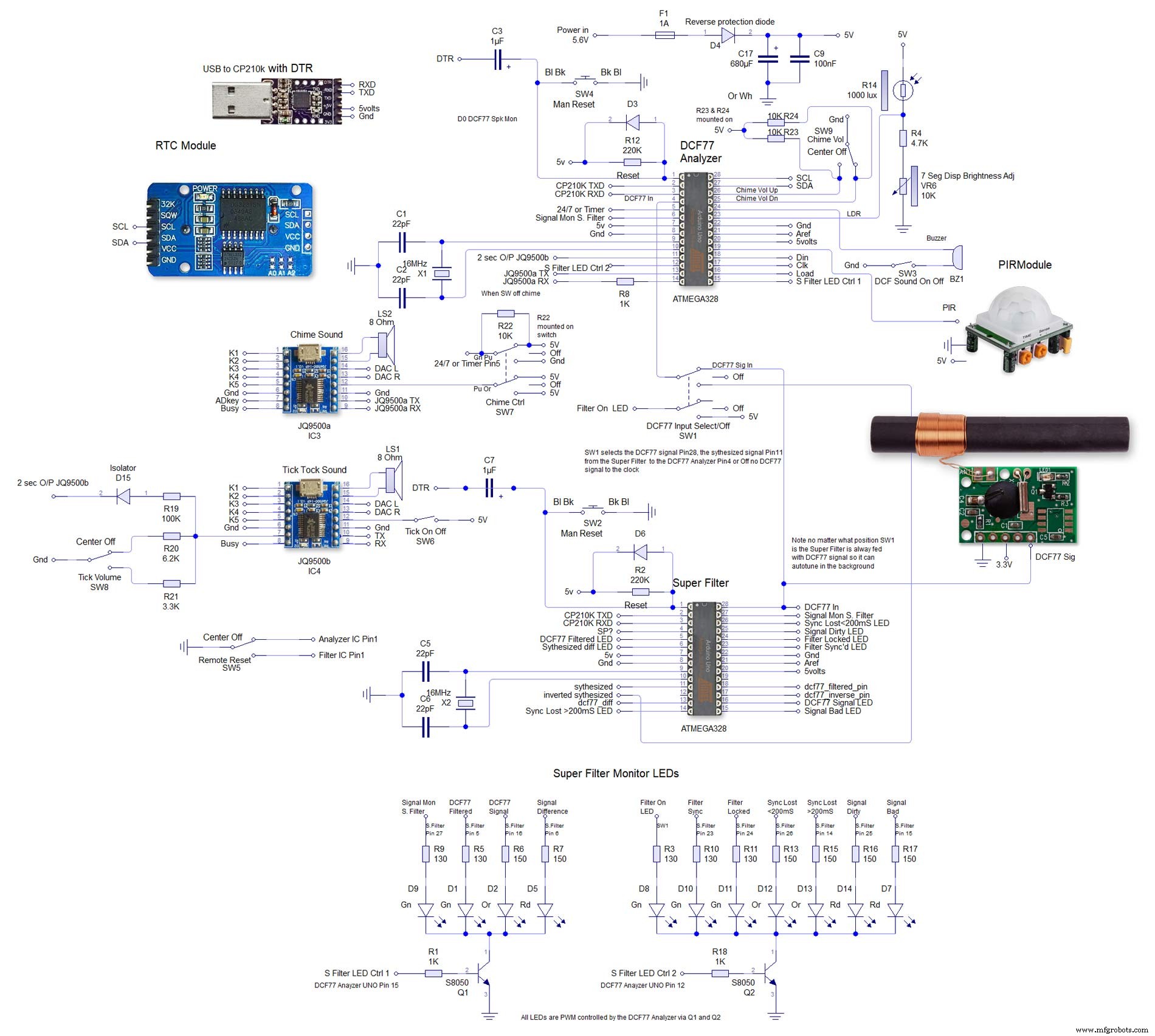
Yang ke-2 sangat besar untuk dan dapat dilihat ukuran penuh di sini skema 4000x4000. Saya telah meletakkannya dengan cara ini untuk membuatnya mudah untuk ditransfer.

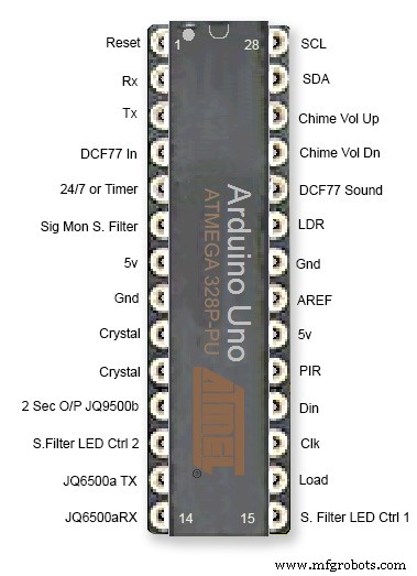
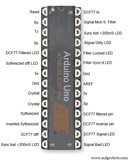
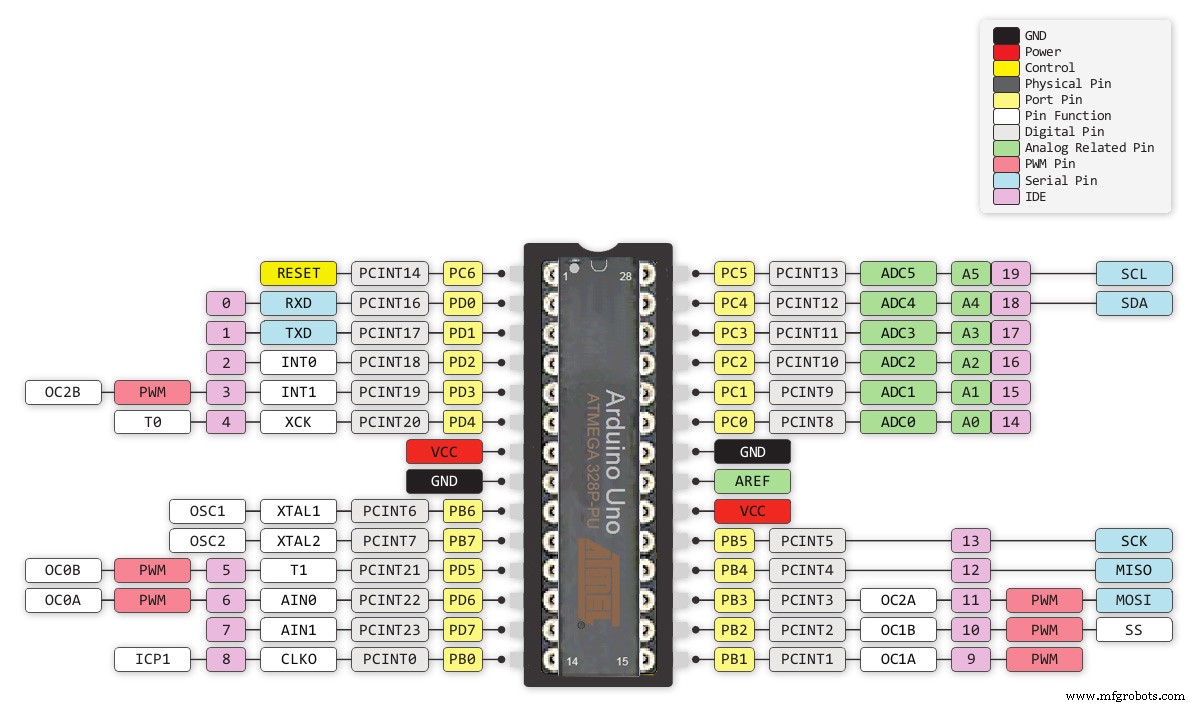
Langkah 5:Koneksi Pin Atmega
Jam ini menggunakan 2 IC Atmega 328 pada Papan vero khusus. UNO standar dapat digunakan untuk bagian Penganalisis jam tetapi UNO dengan kristal kuarsa daripada resonator harus digunakan untuk bagian Filter Super jam. Lihat cara menambahkan kristal kuarsa ke Arduino UNO di sini http://www.brettoliver.org.uk/Master_Clock_MK2/Master_Clock_MK2.htm#Mod
Langkah 6:Tata Letak Papan Vero
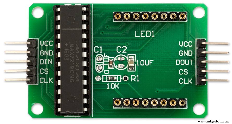
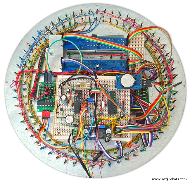
Banyak modul untuk proyek ini sudah dibuat sebelumnya dan hanya perlu dicolokkan tetapi papan utama untuk Arduino, modul suara, dan Matriks LED ke-3 perlu dibuat di papan Vero.
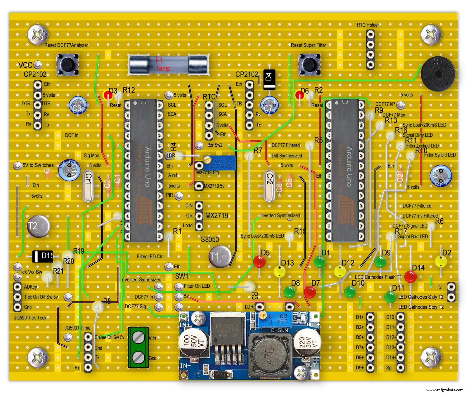
LED ditampilkan dipasang di papan utama untuk referensi saja.
Semua kabel ke papan lain dari papan utama adalah melalui konektor header PCB. Sambungan dari papan utama ke panel sakelar terhubung langsung. Ini memungkinkan papan utama dan panel sakelar dilepas untuk pemeliharaan.
Perhatikan bahwa ini dikonfigurasi sebagai Arduino UNO dan sementara Unos atau Nano yang dibuat sebelumnya dapat digunakan, Filter Super Arduino harus memiliki kristal kuarsa bukan resonator untuk akurasi lihat Koneksi Pin Atmega di atas.
Lihat infonya di situs Master Clock saya modifikasi kristal kuarsa Arduino
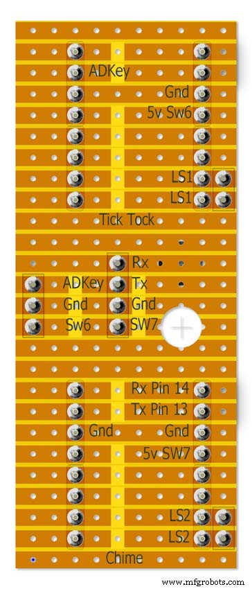

Catatan RTC dipasang di sini tetapi hanya dihubungkan dengan kabel header.
Langkah 7:Modul yang Dibuat Sebelumnya
Papan dan modul yang dibuat sebelumnya
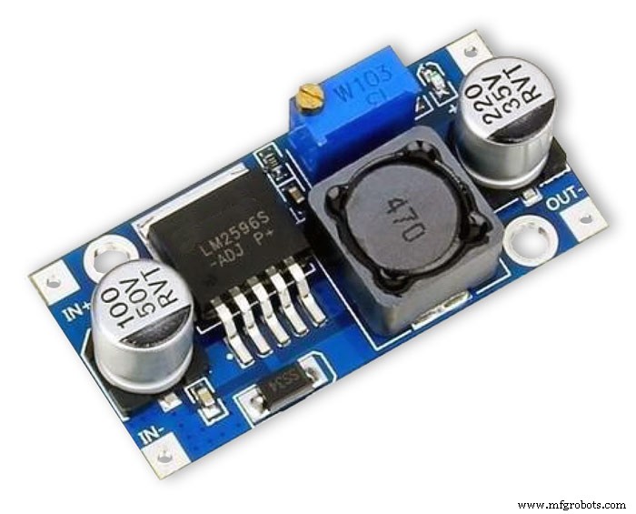
Modul Regulator LM2596 menurunkan tegangan hingga 5v. Ini disesuaikan dengan resistor preset 10K pada modul dan diukur setelah dioda proteksi mundur D4. Sesuaikan ini sebelum menambahkan Arduino ke papan.
Jam menggunakan maksimum sekitar 450mA dengan LED pada kecerahan penuh dan turun menjadi sekitar 80mA dengan tampilan mati.
Anda harus aman dengan PSU DC 1000mA dari 7 -12volt (Modul Regulator LM2596 mengontrol voltase)
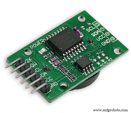
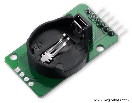
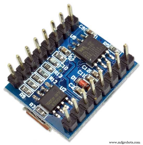
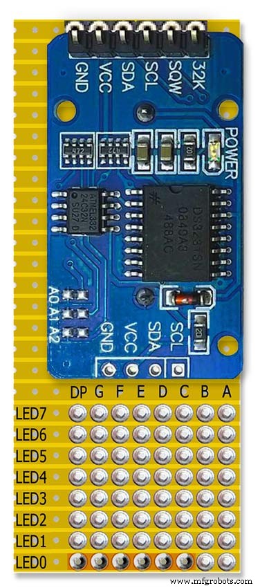
RTC DS3231 I2CModul ini menyimpan waktu dari sinyal DCF77 yang didekodekan. Jam bawaan memiliki kompensasi suhu dan memiliki cadangan baterai jika terjadi kegagalan daya. Perhatikan bahwa modul RTC dimodifikasi untuk menggunakan baterai yang tidak dapat diisi ulang.
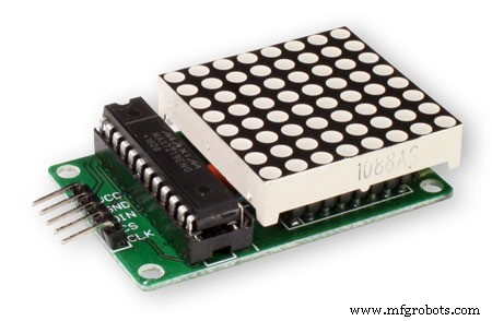
MAX2719 Modul Dot MatrixModul ini menggerakkan cincin LED bagian dalam dan luar (2 modul) dan modul ke-3 menggerakkan semua LED lainnya yang membatasi LED Filter Super. Matriks LED dilepas dan header PCB disolder pada tempatnya.
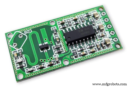
RCWL 0516 Doppler Radar Sensor MicrowaveUntuk menyalakan tampilan jam hanya saat ruangan ditempati saya menggunakan deteksi gerakan. Anda memiliki pilihan antara RCWL 0516 di bawah yang akan mendeteksi gerakan dari balik kaca atau modul PIR di bawah.
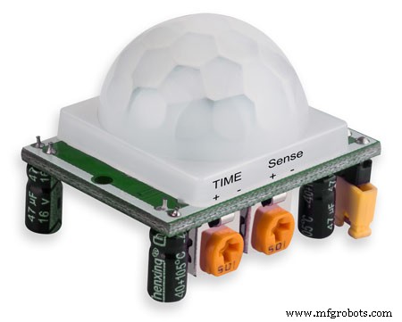
Modul PIR InframerahModul PIR dapat digunakan sebagai pengganti Sensor Radar Doppler di atas. Kekurangan dari perangkat ini adalah tidak dapat digunakan di balik kaca atau perspex dll.

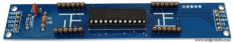
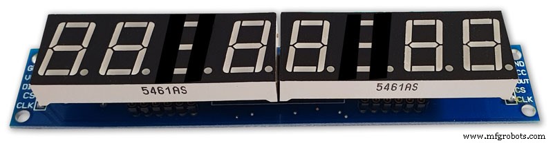
Max2719 7 Segment Display 0.56"Ini adalah versi 0.56" yang lebih besar yang digunakan untuk tampilan waktu dan tanggal. Saya sudah memiliki banyak ini tetapi ada modul serupa di tindie. Pastikan Anda mendapatkan tampilan 0,56" yang lebih besar. Perhatikan bahwa modifikasi kecil mungkin diperlukan untuk mencegah kesalahan tampilan pada modul ini. Lihat langkah modifikasi MAX2719.
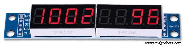
Max2719 7 Segment Display 0.39"Ini adalah versi 0.39" yang lebih kecil yang digunakan untuk tampilan bit, error dan pulsa. Mereka tersedia di seluruh eBay dan Amazon, pastikan Anda mendapatkan modul dengan pin header yang tidak disolder atau papan dengan pin yang disolder ke bagian belakang modul. Catatan modifikasi kecil mungkin diperlukan untuk mencegah kesalahan tampilan pada modul ini. Lihat langkah modifikasi MAX2719.

Modul JQ6500 16p Salah satu modul ini digunakan untuk memainkan suara detak dan yang lainnya lonceng seperempat dan jam. Dengan file suara yang disertakan dengan proyek, Anda seharusnya dapat menggunakan modul 16p termurah dengan memori 2M. Masing-masing modul menggerakkan satu speaker 3W 8Ω. Suara dimuat dari PC Anda (bukan MAC) melalui USB menggunakan program sederhana.
Penerima DCF77
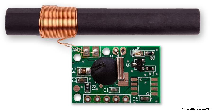
Modul Penerima DCF77 saya dari http://www.pvelectronics.co.uk
Item ini sepertinya tidak tersedia lagi, tetapi coba Amazon
Sambungan Modul Penerima DCF77 PV Electronics Sambungan dari kiri ke kanan
1.VDD 2.TCON 3.PON 4.GND 5.NC
Memberikan output dalam format terbalik (output rendah, dan menjadi tinggi sekali per detik).
Mode siaga daya rendah - sambungkan PON ke Vdd.
Hubungkan PON ke GND untuk operasi normal.
Jauhkan receiver dari TV, monitor, atau kebisingan listrik lainnya dan pastikan itu mengarah ke pemancar DFC77.
Komponen 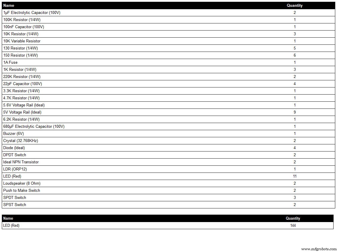
Daftar komponen ini dihasilkan dari program gambar skematik saya LiveWire jadi mungkin tidak menampilkan detail lengkap di mana komponen tidak ada di perpustakaan program, misalnya beberapa sakelar. Periksa skema untuk detailnya atau hubungi saya.
Warna LED dapat dipilih sesuai kebutuhan tetapi lihat bagian LED untuk LED sebenarnya yang saya gunakan.
Langkah 8:Urutan Pengkabelan
Dengan sekitar 400 kabel ganjil untuk menyambungkan kabel, perlu banyak perencanaan agar sesuai dengan jalur kabel di celah antar modul.
Buat modifikasi jika diperlukan dan pasang semua papan ke bagian belakang dial sehingga rangkaian wiring harness terlihat.
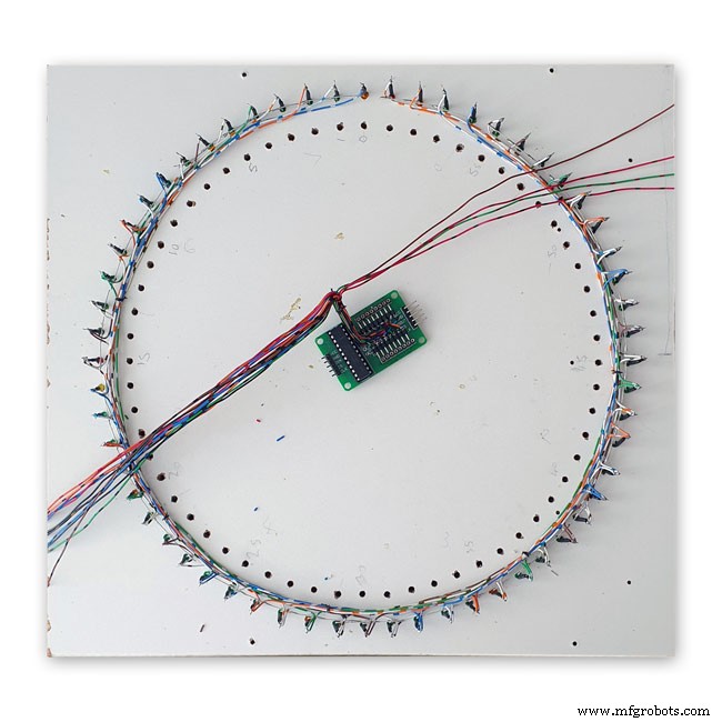
Papan dot matrix dilepas dan disambungkan dari jam.
Pasang LED Super Filter dan pasang ke dial.
Pasang LED Status DCF77 dan paskan ke dial.
Super Filter dan LED Status DCF77 dihubungkan dengan kabel header ke papan utama. Pasang semua LED pada modul dot matrix 3 dan paskan dengan dial.
Sambungkan dari modul dot matrix 3 ke papan vero breakout kecil dan kemudian sambungkan ke LED untuk modul ini yang dipasang pada langkah di atas.
Pasang cincin LED luar dan kemudian paskan ke dial.
Hubungkan layar dot matrix cincin luar meninggalkan ujung kabel cukup lama untuk berakhir pada LED cincin luar.
Pasang kembali tampilan dot matrix lingkar luar dan putuskan harnes kabel ke LED lingkar luar.
Hubungkan cincin LED bagian dalam dan kemudian paskan ke dial.
Hubungkan layar dot matrix cincin bagian dalam dengan membiarkan ujung kabel cukup panjang untuk berakhir pada LED cincin bagian dalam.
Pasang kembali tampilan dot matrix cincin bagian dalam dan akhiri rangkaian kabel ke LED cincin bagian dalam.
Pasang semua LED pada modul dot matrix 3 dan paskan dengan dial.
Sambungkan dari modul dot matrix 3 ke papan vero breakout kecil dan kemudian sambungkan ke LED untuk modul ini yang dipasang pada langkah di atas.
Buat kabel header dan sambungkan ke semua papan.
Pasang Papan Vero utama dan kemudian sambungkan ke panel sakelar. LDR dipasang melalui pintu kayu berengsel yang dipasangi panel sakelar sehingga kabel ini dipasang pada saat yang bersamaan.
Pasang speaker dan sambungkan ke Vero Board dengan modul suara JQ6500.
Jika Anda telah mengebor lubang dengan ukuran yang benar di dial, semua LED akan masuk ke tempatnya tanpa lem. Pastikan tepi bagian dalam lubang LED dilapisi dengan cat/pernis pada tahap pengecatan untuk membantu penyesuaian gesekan.
Langkah 9:Modifikasi Modul Wiring Max2719 Dot Matrix
Sebelum kabel dapat dihubungkan ke modul matriks MAX 2917, kabel tersebut perlu dimodifikasi.
Lepaskan LED Dot Matrix karena ini tidak diperlukan.
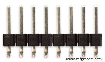
Dua set konektor 8 90° pin akan disolder ke tepi bawah konektor matriks LED yang ada.
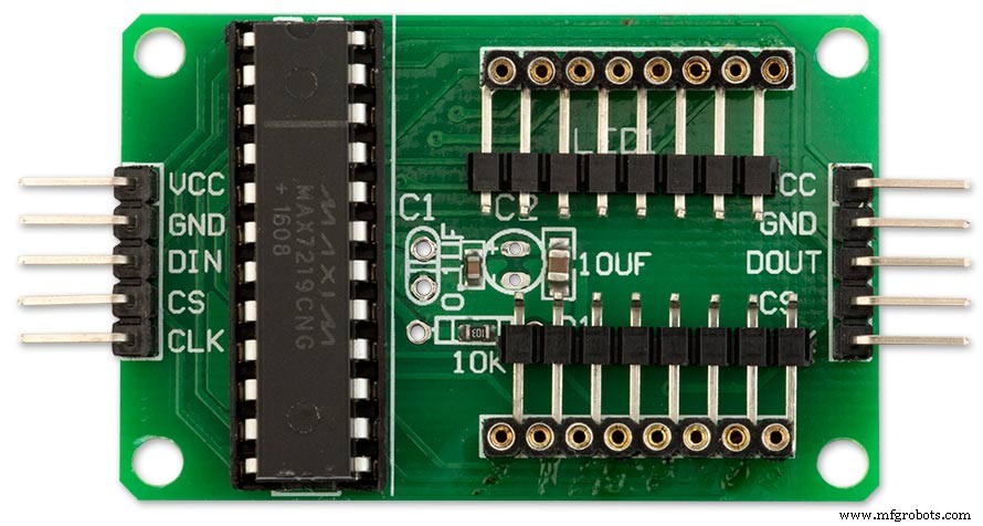
Modul MAX7219 yang dimodifikasi dengan konektor pin 90° disolder ke bagian bawah konektor Matriks LED lama. Kabel diambil dari titik ini ke matriks LED di papan utama.
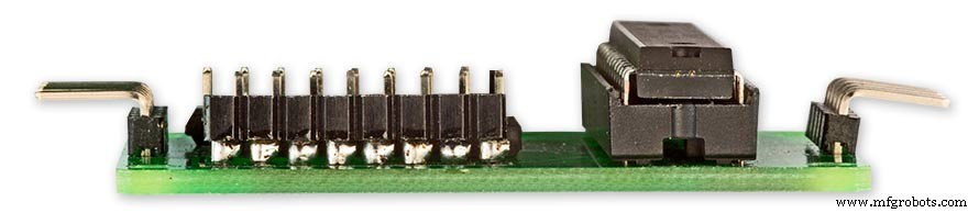
Tampilan samping menunjukkan pin yang disolder ke sisi pin konektor Matriks LED lama tepat di atas PCB.
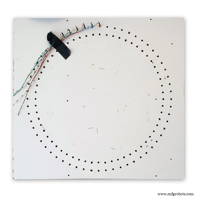
Langkah 10:Pengkabelan Membangun Jig Pengkabelan
Jig akan menahan LED di tempatnya dengan jarak yang benar sehingga memudahkan pemasangan kabel dari jam.
Membangun Jig kabel untuk LED
Cetak dial ke selembar kertas. Cetak terbalik atau letakkan kertas dari belakang ke depan karena Anda akan bekerja dari belakang jam. Letakkan lembaran di atas kayu tua atau melamin. Pukul tengah semua pusat LED dan bor dengan mata bor 3mm. Lubang harus sesuai dengan gesekan pada LED untuk memastikan pemasangan kabel yang mudah. Diameter LED berbeda, jadi lakukan beberapa lubang uji terlebih dahulu untuk mendapatkan ukuran yang tepat untuk LED Anda.
Jig kabel selesai.
Menyelesaikan cincin LED Dalam &Luar pada jig. Mungkin berguna untuk menulis nomor LED dan info lainnya pada jig untuk memastikan Anda memasang LED yang benar karena LED dipasang ke bagian belakang dial dan diputar/berlawanan arah jarum jam.
Cincin LED dilepas dari jig yang siap dimasukkan ke dial.
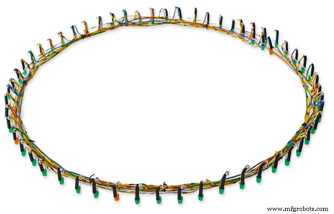
Langkah 11:Pengkabelan LED Cincin Dalam dan Luar 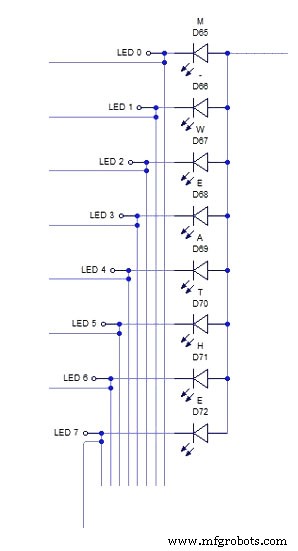
Diagram skema di atas menunjukkan pengkabelan untuk bagian 8 LED dari cincin LED luar.
Pertama dorong delapan LED ke dalam lubang di jig. Tekuk semua anoda sehingga mereka terhubung bersama sesuai dengan shematic dan solder di tempatnya. Sebuah kawat terhubung ke delapan anoda yang terhubung dari modul matriks LED nanti. Pasang sedikit selongsong insulasi di atas katoda kemudian tekuk kaki ini sekitar 15mm dari LED. Potong sekitar 5mm dari tikungan dan solder kawat pendek yang cukup panjang untuk mencapai kumpulan delapan LED berikutnya. Lihat gambar2.
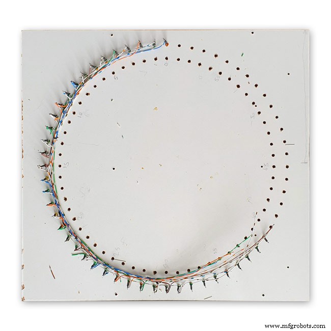
Gambar 1 Ini menunjukkan bagian lengkap dari 8 LED yang dihubungkan pada jig dengan kabel yang mengarah ke bagian 8 LED berikutnya.
Pic 2 Ulangi proses di atas dalam kumpulan delapan LED.
Setiap batch delapan LED akan memiliki koneksi anoda terpisah ke modul dot matrix. Delapan total.
Pic 3 LED cincin luar dilengkapi dengan 16 kabel yang terhubung ke tampilan dot matrix.
LED kemudian didorong ke dalam lubang di dial dan modul matriks dipasang kembali ke dial. Setelah terpasang, 16 kabel dari modul dot matrix dihubungkan ke LED cincin luar. Proses ini diulang untuk cincin LED bagian dalam.
16 kabel dari modul dot matrix siap disambungkan ke 8 set 8 bagian LED. Perhatikan bahwa set ke-8 hanya memiliki 4 LED. Skema 4000x4000 ukuran penuh dapat dilihat di sini.
LED
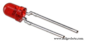
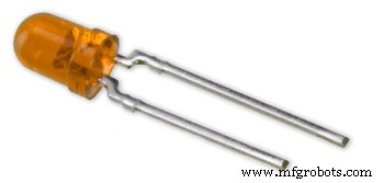
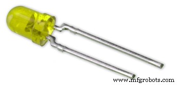
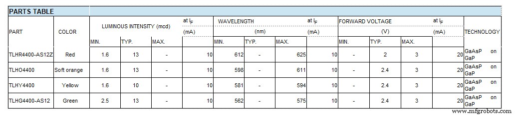
Saya telah menggunakan LED Efisiensi Tinggi seri Vishay TLH44 dalam Paket Difusi Berwarna 3 mm
DESKRIPSI Seri TLH.44.. dikembangkan untuk aplikasi standar seperti indikasi umum dan tujuan pencahayaan. Itu ditempatkan dalam paket plastik difusi berwarna 3 mm. Sudut pandang lebar dari perangkat ini memberikan kontras on-off yang tinggi.
Beberapa jenis pilihan dengan intensitas cahaya yang berbeda ditawarkan. Semua LED dikategorikan dalam kelompok intensitas cahaya. Itu memungkinkan pengguna untuk merakit LED dengan tampilan yang seragam.
FITUR
• Paket standar 3 mm (T-1)
• Toleransi mekanis kecil
• Cocok untuk DC dan arus puncak tinggi
• Sudut pandang lebar
Gambar 1-4 di atas menunjukkan warna LED dengan gambar di bawah menunjukkan grafik dengan nomor bagian yang sebenarnya.
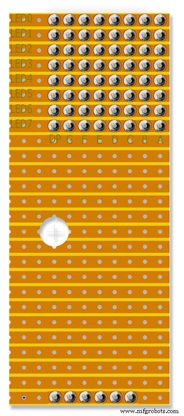
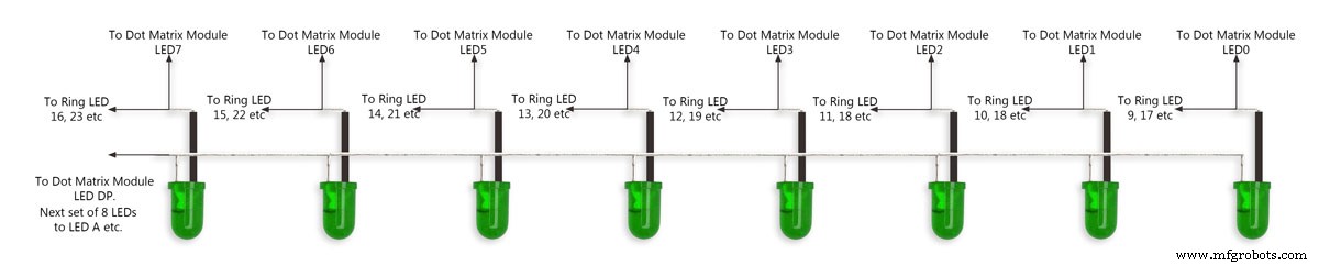
12:Pengkabelan Modul Dot Matrix ke-3
Menghubungkan modul Dot Matrix ke-3
Modul ini hanya memiliki 24 LED yang terhubung dari 64.
LED hari dalam seminggu pada bagian 1 dari 8 LED (hanya 7 yang terhubung)
Ke-2 dari 8 LED adalah CEST, CET Leap Yr, RTC Error, Synced, Error Period dan Error Pulse Width (hanya 7 yang terhubung)
LED ke-3 dari 8 adalah Buffer Full, Parity 3 to 1 pass and fail dan Buffer Oveflow (semua 8 LED terhubung)
4 dari 8 LED hanya berisi 2 LED penanda Menit dan Status DCF77
Saya bisa saja menggunakan 3 set 8 LED tetapi menggunakan 4 set membuat pengkabelan lebih sederhana.
LED ini disambungkan pada wiring jig kemudian disambungkan ke papan Vero kecil di mana mereka terhubung ke kabel Matrix. Perhatikan bahwa papan ini juga berfungsi sebagai dudukan untuk RTC.
Langkah 13:Panel Sakelar Pengkabelan 
Panel sakelar berayun ke bawah di bawah jam yang dipasang di bagian belakang pintu akses. Kabel disolder langsung ke papan utama dan termasuk kabel untuk LDR.

Ganti panel
Pengalihan kabel panel sedang berlangsung
Panel sakelar dengan alat tenun kabel lengkap yang ditunjukkan dipasang ke pintu di dasar jam
Pengkabelan lengkap dengan alat tenun kabel untuk sakelar yang turun dari papan utama. Panel sakelar ditampilkan terlipat ke dalam kotak jam.
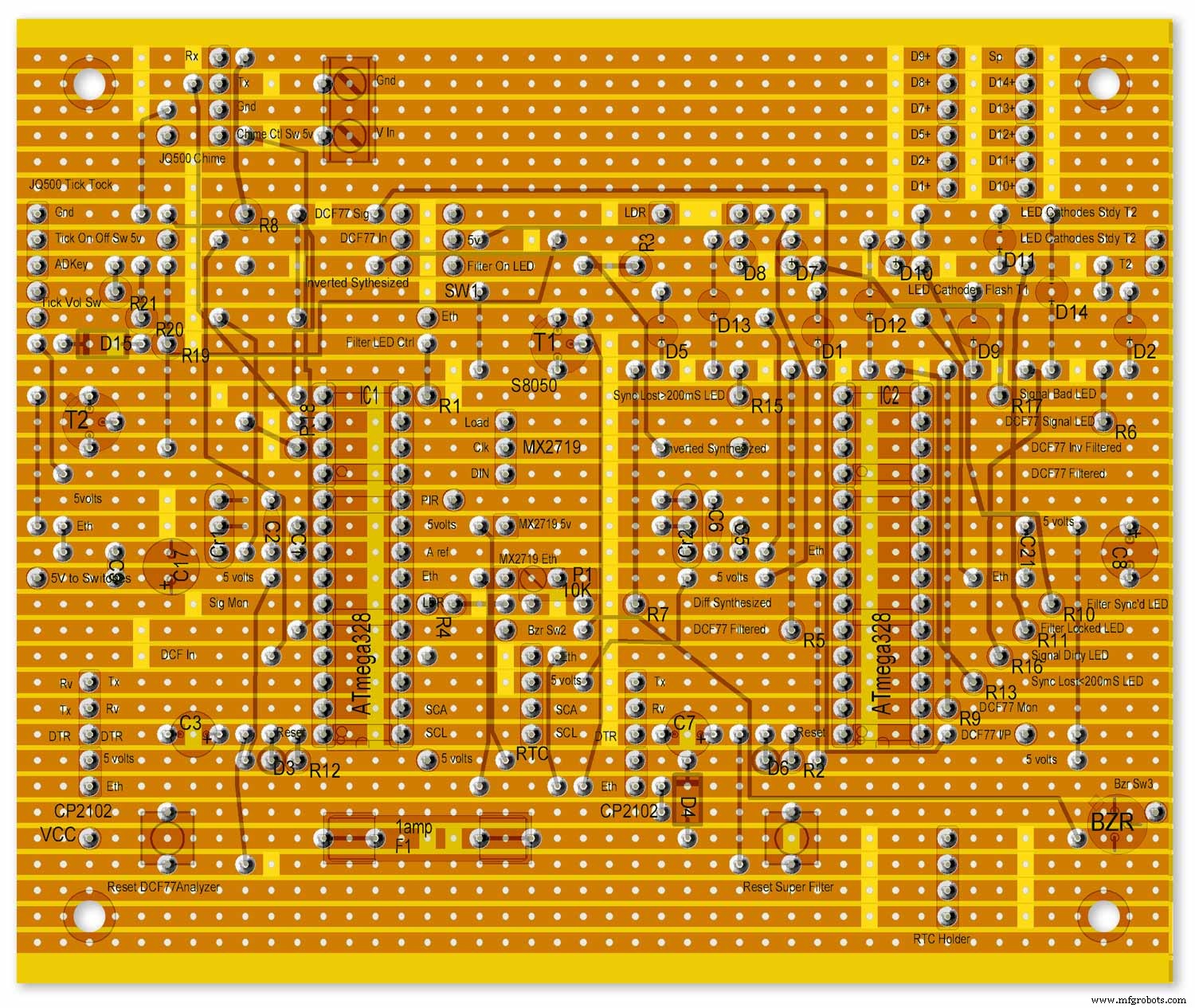
Langkah 14:Bunyi Lonceng dan Centang Tok di JQ6500 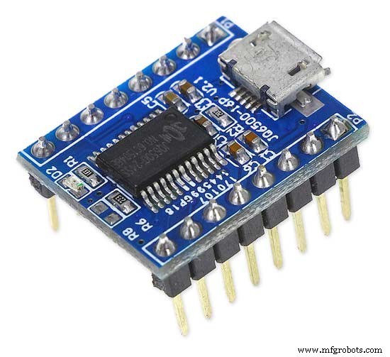

Jam ini menggunakan 2 x modul JQ6500 satu untuk suara tik tok dan satu lagi untuk lonceng seperempat dan jam. Suara tik tok dikendalikan oleh perangkat keras dan lonceng dikendalikan oleh perangkat lunak.
Sirkuit Lonceng
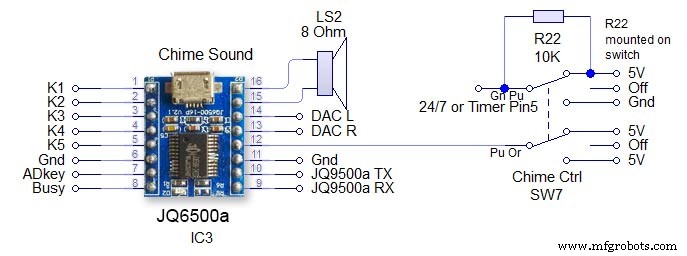
Sakelar SW7 adalah sakelar pengunci 3 posisi. Modul dikendalikan melalui pin perangkat keras serial 13 &14 pada Arduino. Perhatikan resistor 1K pada rangkaian penerima. Lihat skema utama. Mati - daya dicabut dari JQ9500 dan pin 24/7 /timer ditahan tinggi untuk mencegah pin Arduino dibiarkan mengambang 24/7 - Lonceng akan berbunyi empat perempat dan jam 24/7 Jangka waktu - Empat kuartal dan lonceng jam hanya akan berbunyi dari pukul 05:15 sampai pukul 23:00. (diatur dalam kode) Volume diatur dalam perangkat lunak melalui Arduino dan tombol Volume naik atau turun Chime.
Sirkuit Tik Tok
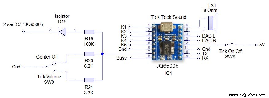
Ini adalah perangkat keras yang dikendalikan langsung ke JQ6500 Switch SW6 Tick On/Off hanya menghilangkan daya dari JQ6500. Tick volume SW8 adalah sakelar penguncian tengah 3 arah. Mengoperasikan sakelar ke atas atau ke bawah mengatur volume melalui pin ADKey pada JQ6500. Perintah untuk memainkan suara tik tok datang setiap 2 detik dari Arduino. File suara harus kurang dari 2 detik. Diode D15 mengisolasi ADKey dari output Arduino.
Langkah 15:Pembicara 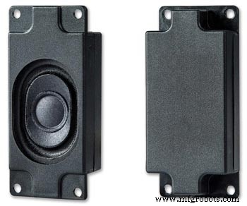
Modul suara masing-masing terhubung ke speaker 3W 8Ω yang terpasang di sisi casing jam. Ini tersedia sebagai pasangan dari Amazon.
Gambar ini menunjukkan lokasi speaker di kotak jam. Perhatikan panel kontrol sakelar yang dilipat di bagian bawah jam.
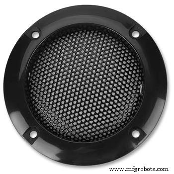
2 panggangan speaker menutupi speaker dan juga dari Amazon
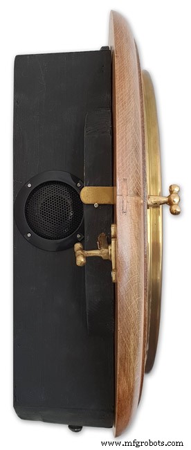
Sisi kiri jam menunjukkan lokasi speaker. Ini diulang di sisi lain.
Jam bergaya bingkai gambar menunjukkan speaker tangan kanan.
Langkah 16:JQ6500 Memuat File Suara
Suara Anda perlu dimuat ke modul JQ6500.
Lihat situs ini untuk info dan perpustakaan Arduino untuk modul ini.
Perpustakaan Arduino JQ6500_SerialInfo UmumAlat JQ6500
Biasanya JQ6500 sudah dimuat sebelumnya dengan program pengunggah musik yang dimuat pada koneksi ke PC Anda (tidak akan berfungsi pada MAC!). This is in Chinese there are instructions on my site here showing how to use the Chinese version.
My JQ6500s came without a loader program so I downloaded an English version from Nikolai Radke
You can get the zip file from here English Language MusicDownload.exe v1.2a
JQ6500_English_MusicDownload_V1_2a.zip
I just run this file from windows (no need to install it) and it runs in English see details below.
Insert your JQ6500 into PC via USB.

When the file is run this window will open. Click FILES
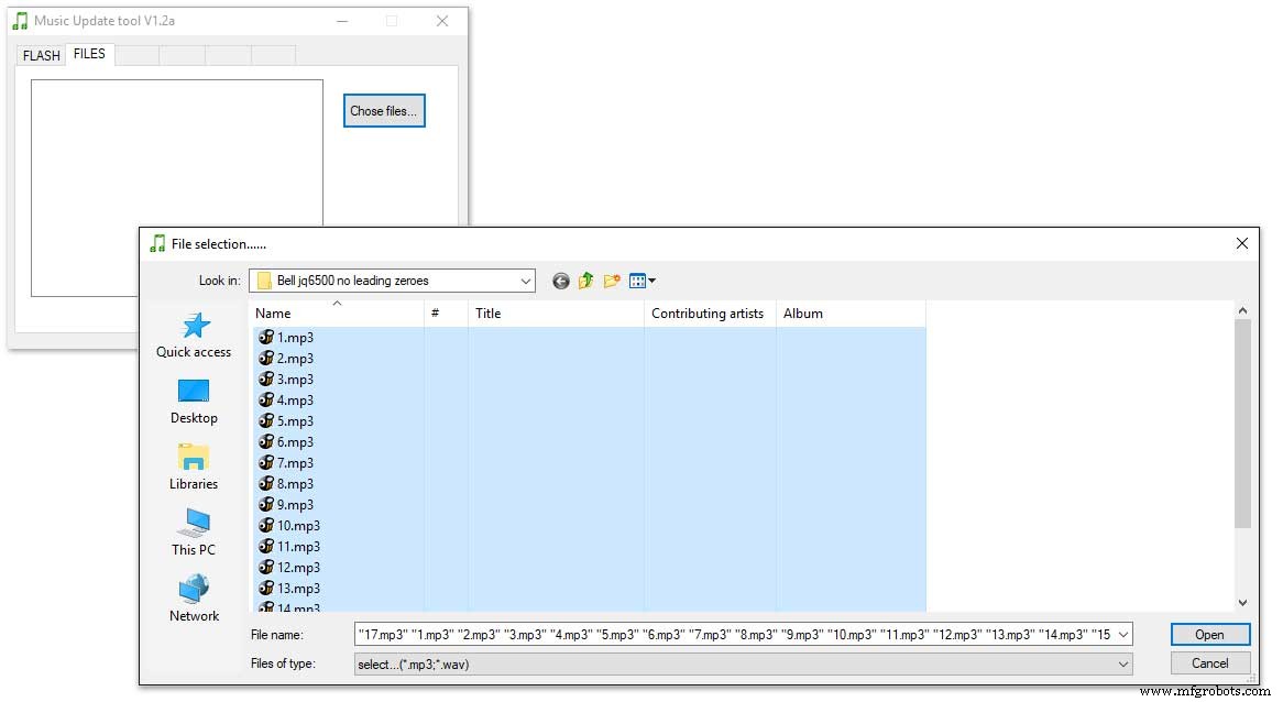
Click CHOSE FILES and shift select all the files you want to be copied to the module. Note make sure your files are named as below.
1 to 12 are the hour chimes. 13 to 16 are the quater chimes and 17 is the test chime used when setting the chime volume using the Chime Volume Switch.
Click OPEN above then click on the FLASH tab.
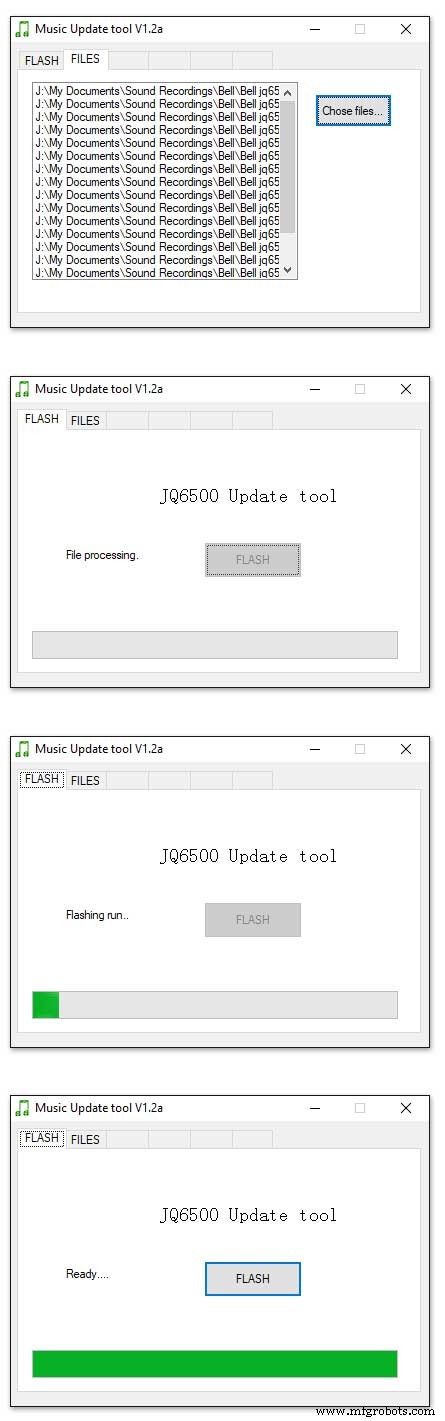
Click on FLASH and you should get a message saying FILE PROCESSING It the files will fit on the module the message will change to FLASHING RUN and a green bar will show progress.
When flashing is completed the message will change to READY......You can remove your module and plug it into sound board on the clock.
Repeat this for the Tick Tock sound (1 file this time) on the 2nd module.
Sound files are enclosed. I mixed these sound files up on Audacity pic 4 at 48KHz sample rate the max quality the JG6500 board can handle. The chimes were mixed on multiple channels to get the real harmonics then mixed back down to a single channel for the JQ6500.
bell.zip tick_tock.zip
Step 17:JQ6500 Library Modification
Modify the JQ6500_Serial.cpp file in your Arduino libray folder
Using the standard library every time a chime is played the library waits in case there is a reponse. This wait causes the clock run out of sync and any received data errors until the next minute.
I found this on google and is a reply from the author of the library. ~~~~~~~~~~~~~~~~~~~~~~~~~~~~~~~~~~~~~~~~~~~~~~~~~~~~~~~~~~~~ Before sending a command, the library waits for up to 10ms to see if there is any left over data from the device... https://github.com/sleemanj/JQ6500_Serial/blob/ma... after sending the command the library waits for a response for up to 1000ms
https://github.com/sleemanj/JQ6500_Serial/blob/ma... and after that it will wait at least 150ms while reading the response
https://github.com/sleemanj/JQ6500_Serial/blob/ma... since in the case of playFileByIndexNumber you don't need a response at all
https://github.com/sleemanj/JQ6500_Serial/blob/ma... you could perhaps get away with adding if(!responseBuffer &&!bufferLength) return;immediately after the last command byte is written (currently line 263 of JQ6500_Serial.cpp)
https://github.com/sleemanj/JQ6500_Serial/blob/ma... that should reduce the time required to about 10-20ms probably.
~~~~~~~~~~~~~~~~~~~~~~~~~~~~~~~~~~~~~~~~~~~~~~~~~~~~~~~~~~~~~~~~
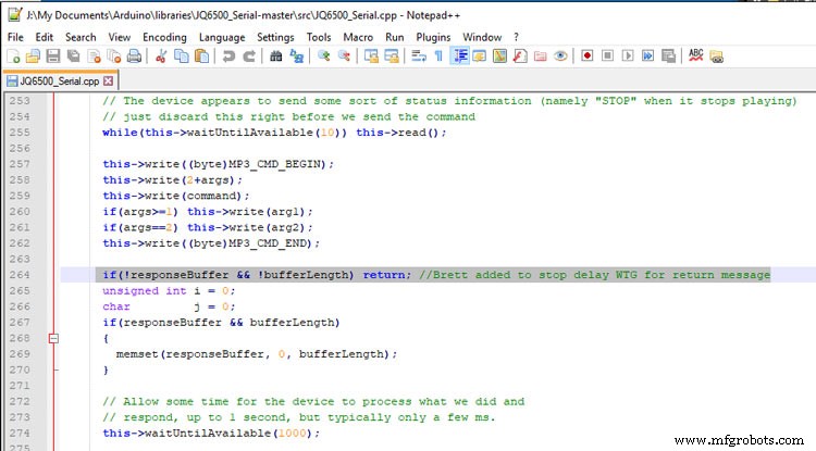
After adding the line after line 263 if(!responseBuffer &&!bufferLength) return; the clock worked fine.
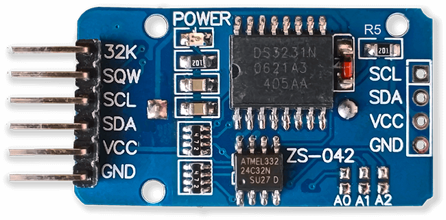
Step 18:Modify the Real Time Clock RTC
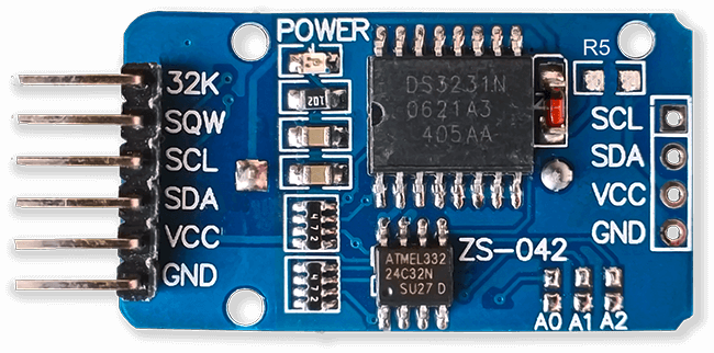
Modification of DS3231 AT24C32 I2C Precision Real Time Clock Module
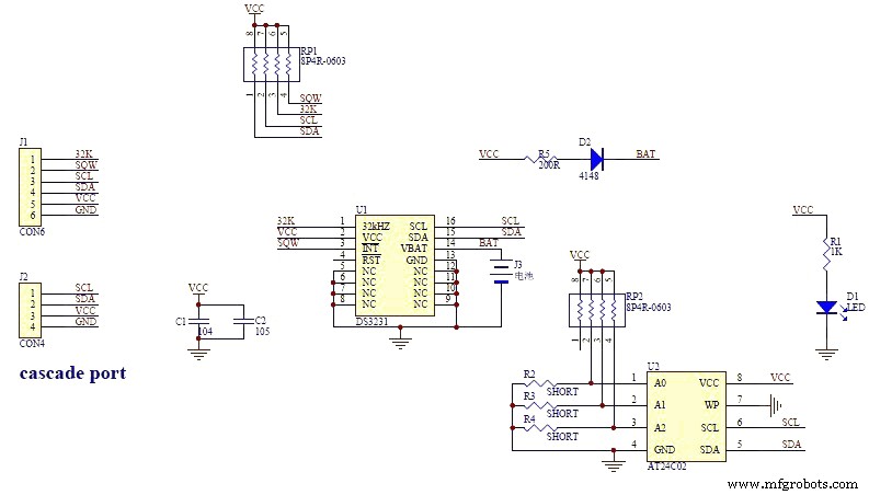
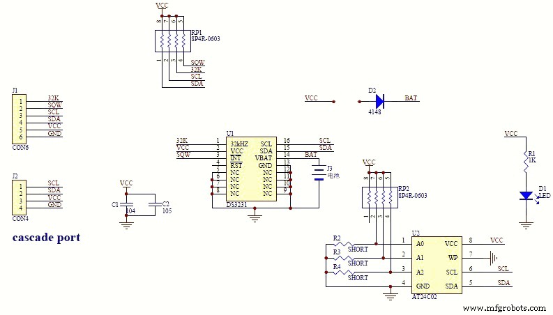
My clock uses a DS3231 AT24C32 I2C Precision Real Time Clock Module.The module comes supplied with a Lithium-Ion rechargeable battery see pic 1. I use a non rechargeable battery so have removed resistor R5 from the module as pic 2.
Step 19:Dial Construction Drawing 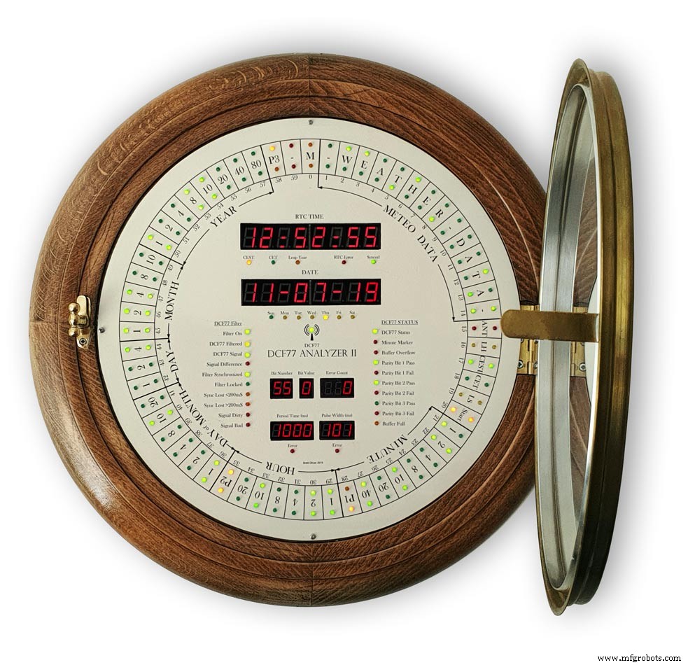
The dial requires oround 700 seperate drilling operations and numerous aounts of cutting and filling to complete.
I don't have a CNC machine so it was all done by hand.
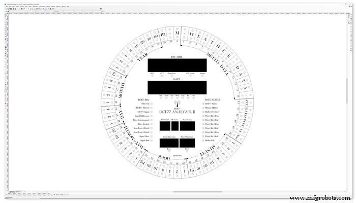
The dial was drawn up on a Cad program (TurboCab) pic 4 and printed out onto injet water slide decal paper.
This shows a close up of dial printing with 3mm LEDs to give an idea of scale. The quality from the water slide decal paper is very good far better than my old ink jet can print.
The enclosed zip file contains the dial picture in various file formats including a 4000x4000 png file.
Contact me for other file types!
TurboCad_Drawings.zip
Step 20:Dial Construction Cutting Out &Drilling 
The dial is cut from 1.5mm thick alluminium sheet as it has to carry the weight of all the electronics and wiring.
Make a template by printing out the dial from your CAD program onto A3 paper.Make sure it has center marks for the LED holes and also the cutouts for the 7 segment LED displays.
Carefully cutout the 7 segment display openings on the template with a craft knife.Place the template on the alluminium sheet and tape it down to stop it moving. Center punch all the center marks for the LEDs and draw around the openings for the 7 segment displays with a marker pen.
Remove the template to reveal the cutting/drilling marks on the alluminium sheets protective film.
Draw a circle the size of your dial with a compass using the center punch mark from the DCF77 symbel LED as a center point.
Cut out the circle with a hacksaw/jigsaw or bandsaw fitted with a metal cutting blade.

Cut out the 7 segment display openings with a coping/jig or fret saw. Take your time with this as it will save a lot of filing later.

Drill out all the holes for the LEDs. I start with a 1mm bit then a 2mm and then finally a 3mm bit.
This leaves the LEDs a friction fit once the paint and varnish is applied to the dial.
Mark center punch and drill 3 or 4 dial mounting holes.
With the holes drilled the protective film can be removed from the alluminium sheet and the dial rubbed down to remove all rough edges.
This will also give a good key for the paint.
Prime and paint with acrylic paint then a coat of matt varnish. Antique White looks better on old dials or use pure white on modern dials.
Step 21:Dial Construction Applying the Dial Transfer Decal 
Water slide decals are printed out on special paper on an inkjet printer. Once dry they are soaked in water then slid into place.
They give a very detailed print and once given a coat of varnish are tough. Don't forget to order transparent tranfers so the dial colour can be seen through the transfer. Follow the instructions with the pack as they do vary.
On my transfers I print out the dial on transfer paper let it dry and then cut it out to just under the size of the dial. I then give it a coat of acrylic varnish. When the varnish is dry the transfer is soaked in water until the transparent transfer comes away from the white backing sheet.
Line up the transfer with the dial and slide it over the dial.
Make sure the center dots line up with the center of the holes in the dial then slide the backing sheet back off the transfer.
Carry out any final adjustments then remove any airbubbles.
Allow to dry then apply some clear acrylic varnish to protect the transfer. Once this dries carfully cut away the transfer around the 7 segment display cutouts with a craft knife. Then cut the transfer off all the LEDs hole. I used a leather punch just smaller than the hole. Give it another coat of varnish to seal all the cut edges Leave it overnight to dry.

Search for "Transparent Water Slide Decal Paper A3"
Step 22:Dial Construction PCB/Vero Board Mounts 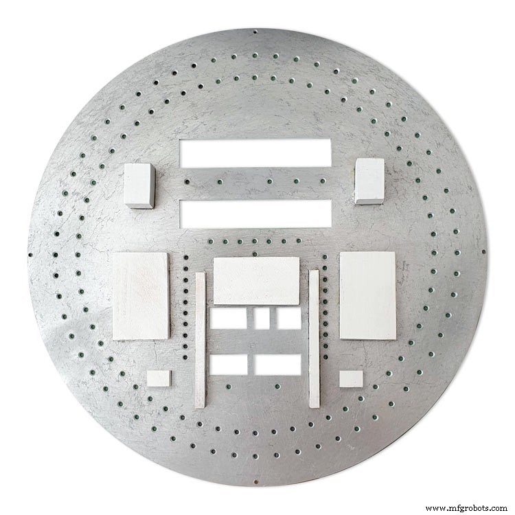
The PCBs and Vero Boards are fixed to wooden mounting blocks cut from off cuts of timber.These block are glued to the dial with impact adhesive. Follow the instructions on the impact adhesive but normaly you apply to both surfaces leave until tacky then press together for an instant bond that hardens fully over night.
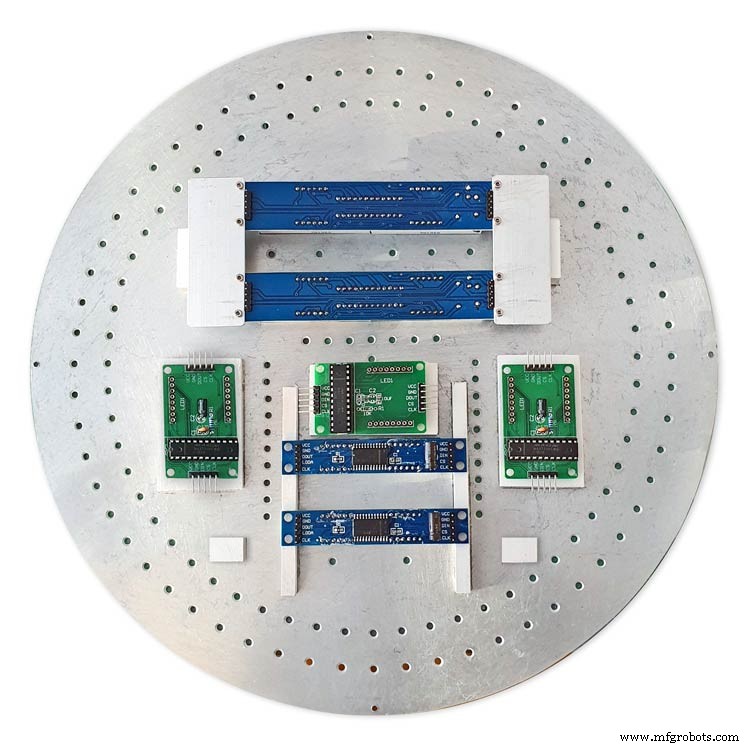
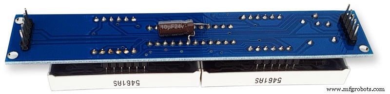
Lower modules in position on the wooden blocks ready to be secured by M2 screws.The main PCB fits on top of the lower 7 segment modules and is raised up on brackets.
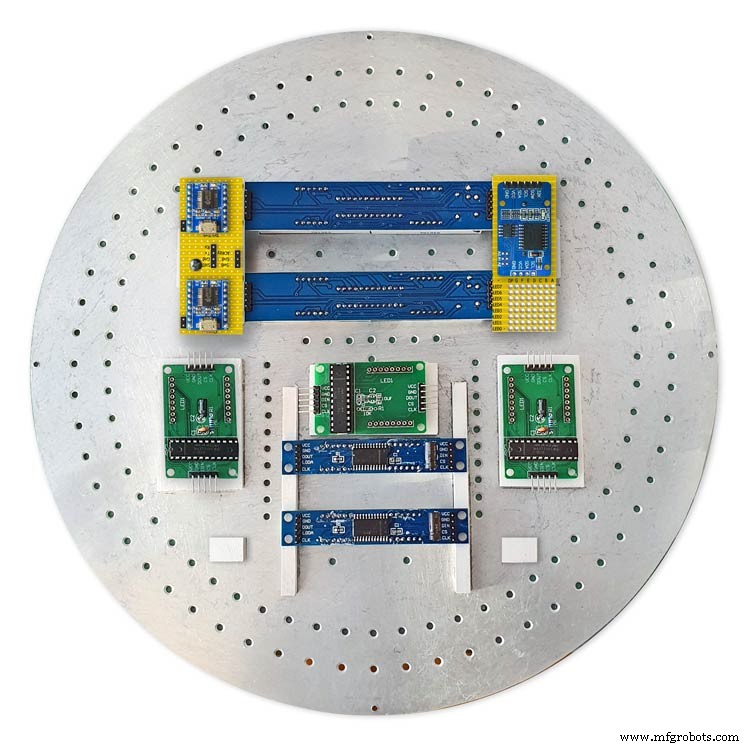
JQ6500 sound module board and LED wiring board in place. RTC is mounted on the LED wiring board but connected on the main board.
Main board mounted on custom made standoff brackets.
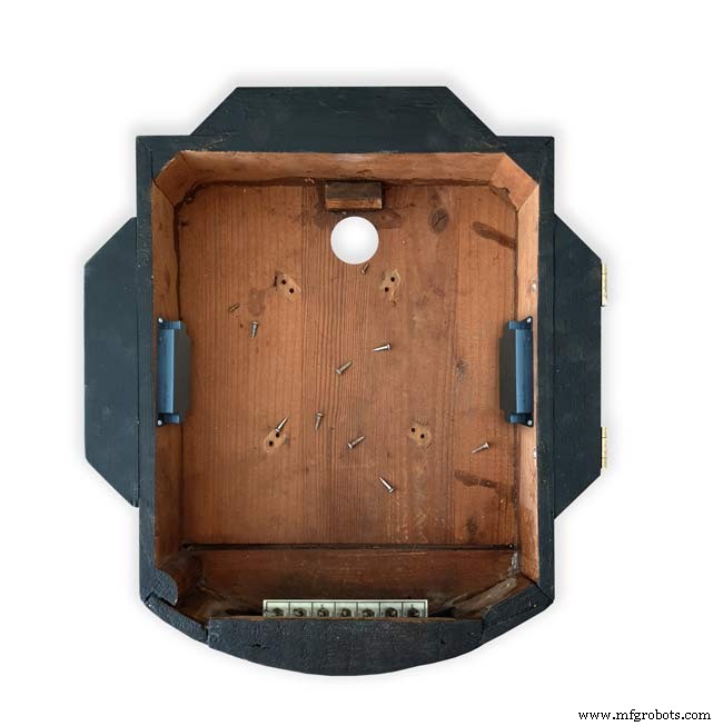
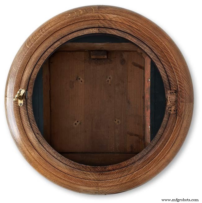
Step 23:Dial Surround &Back Box Restoration
Dial Surround Restoration
I sourced my clock case from eBay. It had no dial or brass bezal and the rear box was broken.
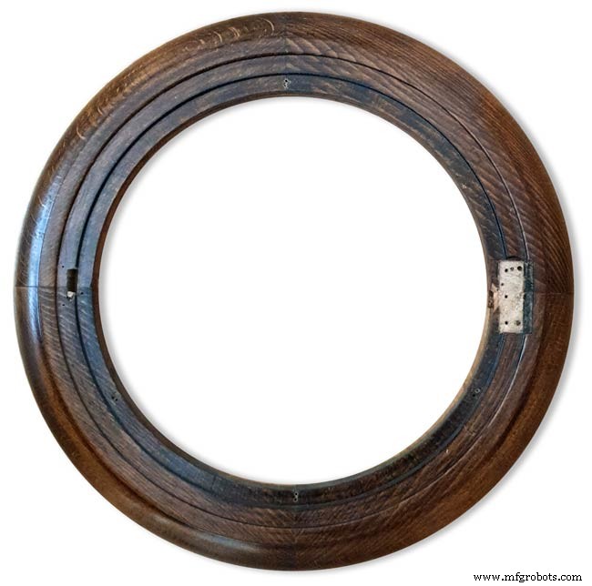
The original Oak dial surround was covered in a thick coat of varnish and years of dirt.
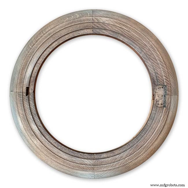
I used paint stripper to remove the varnish and then wood bleach to get rid of the very dark areas of wood.
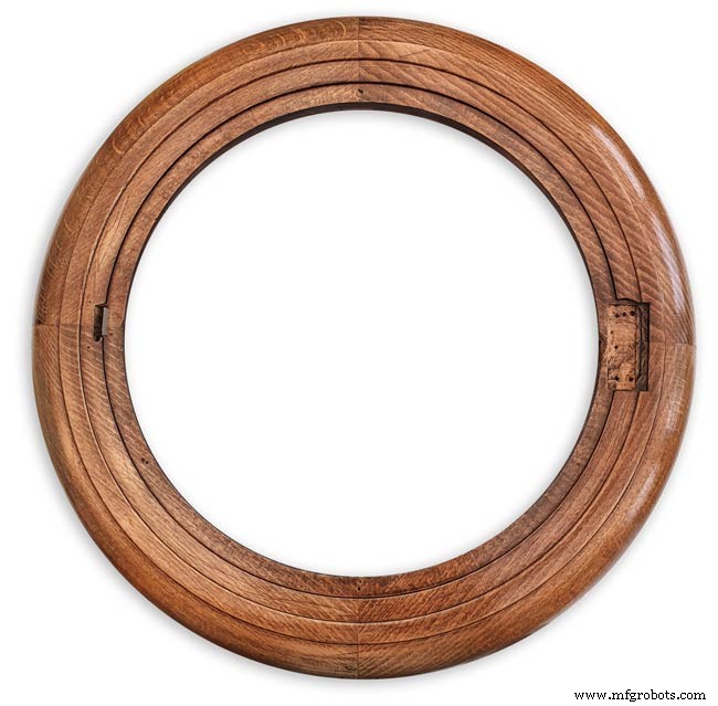
The surround was then varnished with matt acrylic to enhance the grain of the wood.
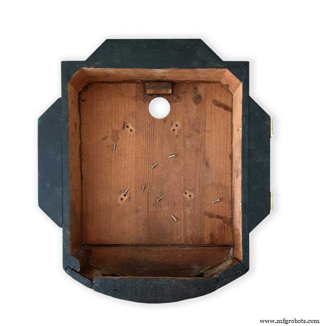
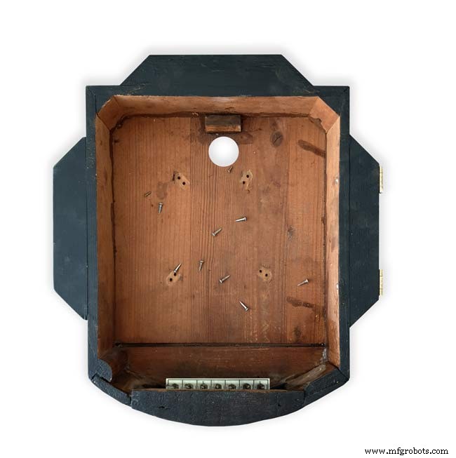
The back box was very badly damaged and had to be screwed and glued back together. I has to fill many hole and cracks in the wood work and decided to paint it matt black.
Step 24:Correcting MAX7219 7 Segment Module Display Errors
The 7 segment modules seem to work fine work fine on their own. However, once you start daisy chaining them together the displays tend to error.
0.39" Display

The datasheet calls for a 10μF and 0.1μ capacitor across the supply rails as close to the MAX7219 as possible.I notice the 0.1μF capacitor is in place but the 10μF capacitor is missing.
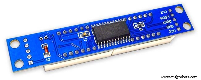
Add this capacitor in the 2 holes above the diode D1 on the rear of the display.

There is also a diode in series with the supply rail. When daisy chaining modules all these diodes are in series so the further down the line of modules the more volts are dropped causing display errors.
Remove this diode on each display and replace it with a wire strap.
0.56" Display
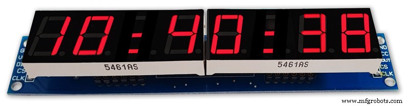
Note the black tape over the 3rd and 6th digit tp make colons.
10μF capacitor added to the rear of the PCB on the +&- pins of the MAX7219 IC
The 1N4148 diode is replaced by a wire link.
Step 25:Increasing the Constrast on the 7 Segment Modules 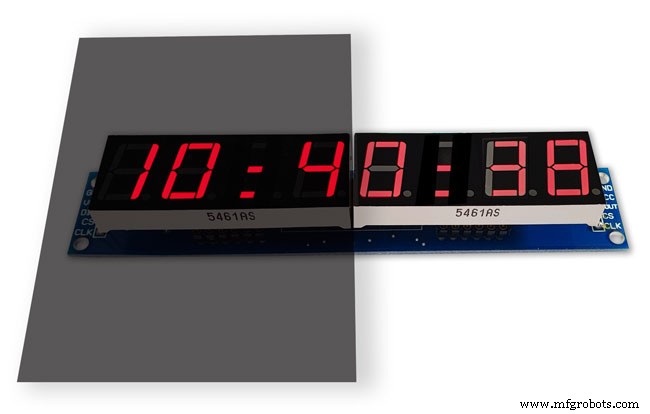
The 7 segment displays traditionally would have a sheet of red perspex to match the LED colour placed over the top of the display. This was designed to hide the not lit segments and provide contrast to the LED segments that are on.
In my clock I have used Neutral Density Heat Proof Dimming Transparent Acetate Sheet ND 0.9.
This hide the not lit LED segments and provides the contrast needed in bright conditions. It has the advantage that it work on all colour LEDs.
My 0.56" modules are a deeper red than the 0.39" modules so I would need 2 different matching red perspex to sheets to work well on both modules.
The acetae shhet is also very cheap the only disadvantage is that it is too flimsy to cover large areas without support.
The picture above shows the effect of the ND sheet. The lit LED segements have more contrast and the unlit LED segments are hidden. It also hides the black tape masking for the colon display.
Step 26:Modification of the RTC Time 7 Segment Display Module to Show Colon Digit Seperators 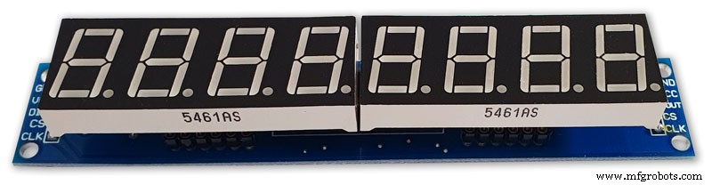
The standard display only has decimal points to separate the digits and has no colon that would normally be used in a clock display.
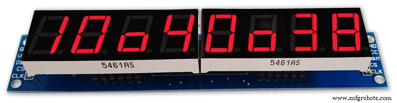
In code I have set digits 3 and 6 to always display a "o" lower case o
Black plastic tape is then cut with a craft knife and placed over the 2 digits leaving a small section showing

When the display is on these visible sections now display colons
Step 27:Dial &Case Fitting 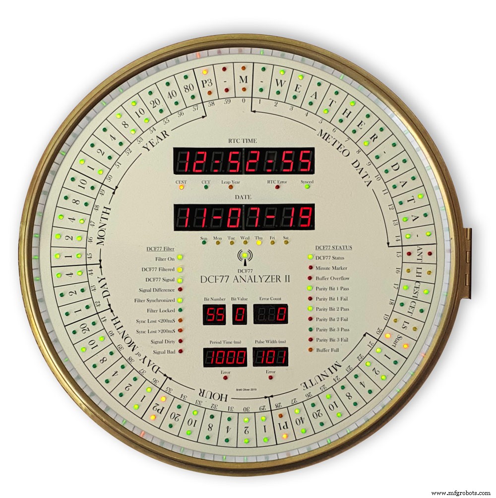
The dial is hidden behind a brass bezal. The brass bezal was missing from my clock but I was able to get one from a horological supplier.
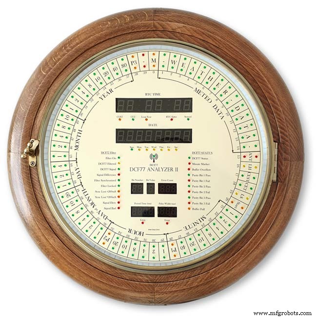
The brass bezal is held down by a brass catch set into the dial surround.

With the brass bezal removed you can see the recess cut in the surround for the brass bezal hidge. My new bezal hinge was a differnet shape to the original hinge so I had to cut it in with a chisle at the front and fill the rear in with a piece of wood stained to match the surround.
The dial has been removed showing the dial mounting holes on the wood surround and the wooden back box behind it.
Shows the surround removed revealing the back box construction. The switch panel can be seen folded up above the trap door in the base of the back box.

Shows the side view of the case with dial and wood dial surround locked in place. The dial surround is locked by the same type of catch used to lock the brass bezal in place. Note the small brass screw below the brass tag on the dial bezal. this ensurse the brass bezal lines up correctly with the dial when the brass bezal is closed.
Step 28:Dial &Case Fitting Modern Style Case and Surround 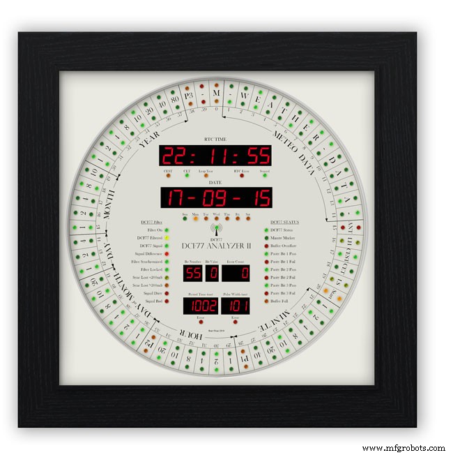
This case uses a large picture frame with a basic square back box to hold the electronics and to hold the dial away from the wall to give it some depth.
Outer frame and glass removed to reveal the thick photomount card over the dial (a thin ply or wood sheet can also be used with a routed edge)
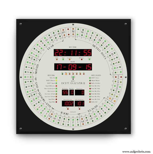
Photo mount removed to show how the dial is fixed to the back plate with 4 small screws.
The backplate holds the dial and has a large circular cutout for the electronics.

It is hinged at one edge to the dial can swing out.
The speakers are mounted on both sides with holes and grills as per the other case.

The switches are mounted on the side in a cutout with the speaker grill above.
Step 29:DCF77 Filter
DCF77 Filter
When switched on the Udo Klein's Super Filter actively processes the incoming DCF77 signal from the antenna/receiver. After a few minutes of sampling the DCF77 signal the Super Filter will predict the DCF77 signal and use this to determine if the incoming signal contains any errors. The Super Filter will then synthesize a corrected DCF77 signal even if the signal is absent.
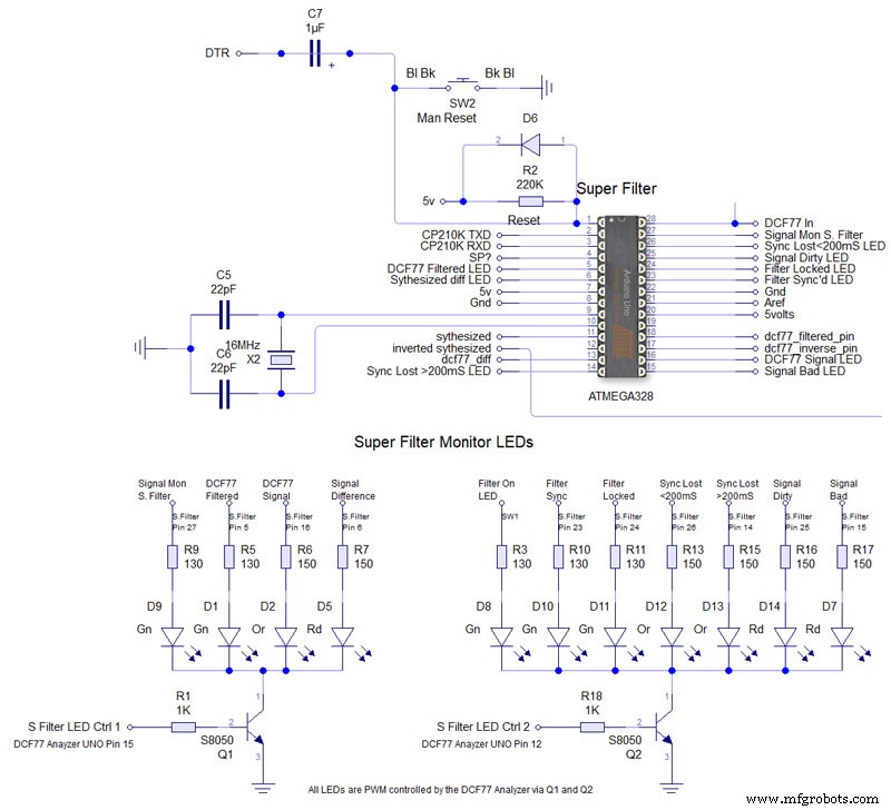
Super Filter Mod See the schematic. I have modified the Super Filter Code to add extra monitor LEDs. In order to do this I have removed 4 modes from the filter just leaving sythesized and inverted sythesized.
Note the PWM LED brightness control is via the Arduino controlling the DCF77 decoding not the Super Filter Arduino. I have also added an LED test to the Super Filter to Match the LED Test on the main clock. This activates on reset or power up. On power up the Supe Filter LED test starts and finishes then the main clock LED terst starts.
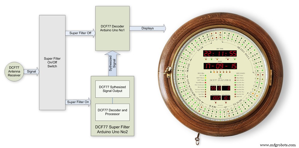
The filter will lock onto the DCF77 signal even if the signal is really noisy. As days progress the filter uses the incomming DCF77 signal to adjust the Arduino crystal frequncy.
This means the filter will stay in time even if the DCF77 signal is lost for many days. In my clock the DCF77 signal is alway fed to the Super Filter Arduino even if the DCF77 Source switch is set to off. This allows the Super Filter to stay in sync and keep adjusting the quartz crystal from the Arduino.
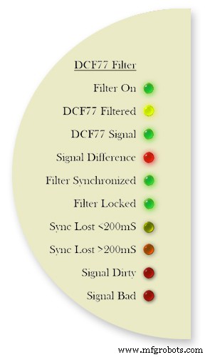
Filter On lights when the DCF77 Source switch is set to FILTER and means the Super Filter is decoding and synthesizing the DCF77 signal
DCF77 Filtered the DCF77 Synthesized signal comming out from the Super Filter
DCF77 Signal the DCF77 signal comming direct from the DCF77 receiver with no filter applied
Signal Difference the differnece between the incomming DCF77 signal and the Synthesized signal. In normal operation this will flash as the received signal shape is often slightly “wider” than the synthesized signal.
Filter Syncronized best possible quality, clock is 100% synced
Filter Locked clock driven by accurate phase, time is accurate but not all decoder stages have sufficient quality for sync
Sync Lost <200mS clock was once synced, inaccuracy below 200 ms, may re-lock if a valid phase is detected
Sync Lost>200mS clock was once synced but now may deviate more than 200 ms, must not re-lock if valid phase is detected Signal Dirtytime data available but unreliable Signal Bad waiting for good enough signal
More details on some of the above
Filter Syncronized - Timing is completely locked to DCF77 and the data is most up to date.
Filter Locked - If the quality factor of the decoder stages drops but the quality factor of the phase decoder stays high enough the clock will transition into the state locked. In this state it is still phase locked to DCF77 but it may become out of sync by a second but only if a leap second is transmitted.
Sync Lost <200mS - This indicates that the quality factor of the decoder stage and the quality factor of the phase decoder have dropped. In this state the timer relies on the quartz crystal timimgs and the clock will slowly drift out of phase with the DCF77 signal. This is a warning that the clock may be running slightly out of sync.
Sync Lost>200mS - Once the clock has started to drift out of phase for more than a set period of time (depending on the tuned accuracy of the quartz crystal) then this LED will light
Animation showing filter synchronized
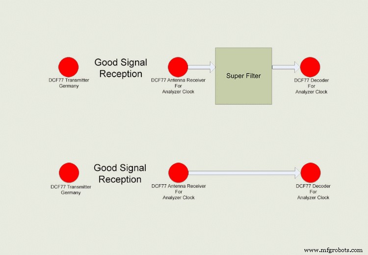
Super Filter example
The top row shows the Super Filter turned on. Once synchronized and tuned into the signal the Super Filter will synthesize a good signal even when the signal is completely lost. On a noisy signal the Super Filter will search for known signal bits and keep itself synchronized to the transmitter. The bottom row shows the Super Filter turned off. Whatever signal is received (good or bad) is sent to the decoder.
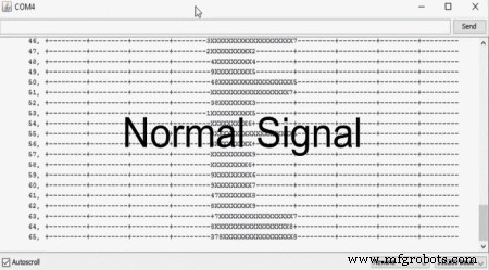
Super Filter correcting a noisy signal as displayed on the DCF77 Scope included with the DCF77 library.
Normal Signal No super filter - Normal signal from the DCF77 reciever Noisy
Signal No Super Filter - The aerial is moved near a LCD screen to generate noiseover the signal
No Signal- The aerial is disconnected and moved connected via the super filter
Noise On Superfilter On- The noise is filtered out leaving a perfect signal.
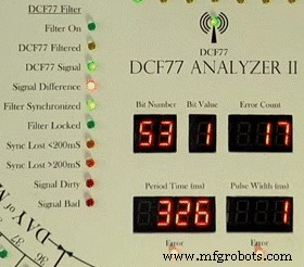
Super Filter turned Off and a bad signal the clock errors and will reject this minutes data.Note the DCF77 Filtered LED pulses as normal but as the Filter is turned off the filtered signal is not fed to the clock's decoder.
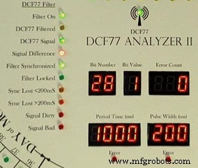
Super Filter turned On and a bad signal the clock has no errors and the clock is able to decode the data as normal.Note the DCF77 Filtered LED pulses as normal and is fed to the clock's decoder
Step 30:DCF77 Time Code 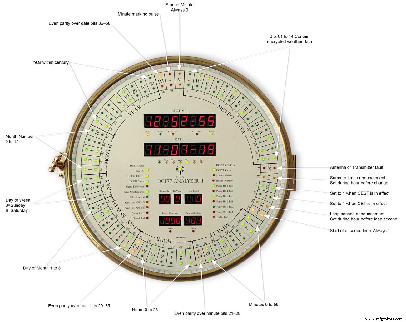
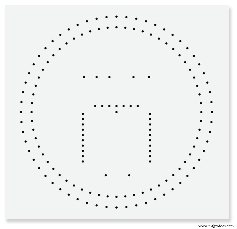
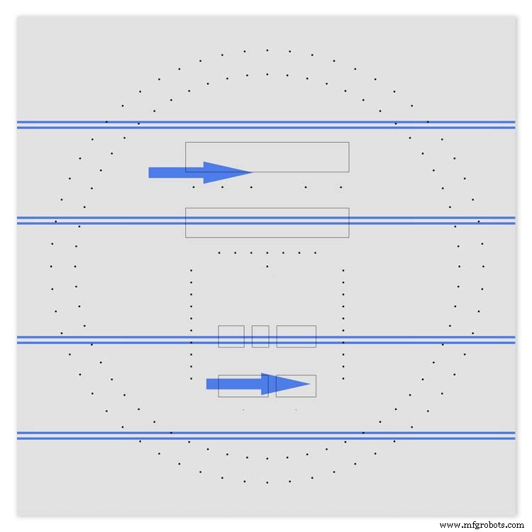
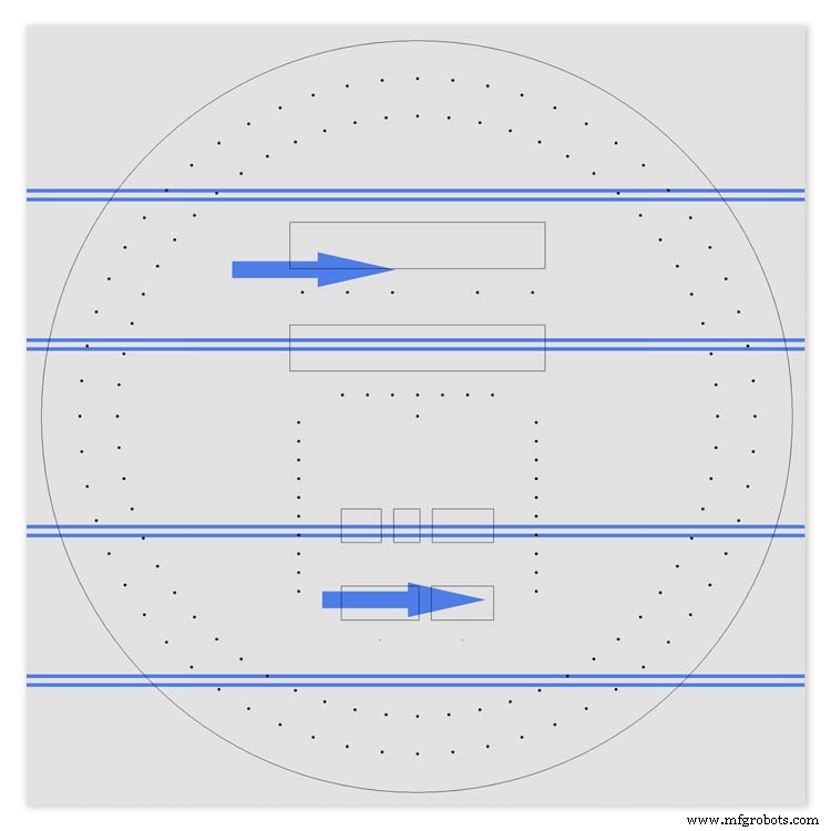
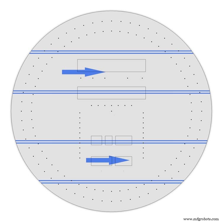
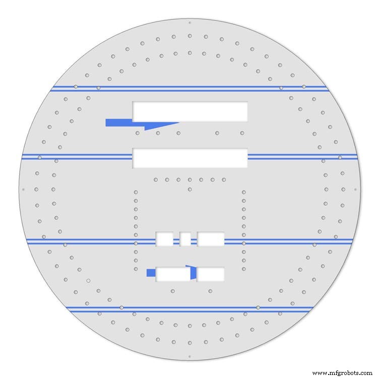
This picture shows the dial code as it is displayed on my dial and allows you to read the incomming DCF77 signal.
Step 31:Code
There are 2 seperates codes to download one for the Superfilter and one for the Analyzer part of the clock.
DCF_77_ANALYZER_CLOCK_Mk2_43.zip Superfilter07DCF77AnalyzerMK2.zip
Kode
- DCF77 Decoder Code
- Super Filter Code
DCF77 Decoder CodeArduino
This is the code loaded onto DCF77 analyzer ArduinoNo preview (download only).
Super Filter CodeArduino
This is the code loaded onto DCF77 Super Filter ArduinoNo preview (download only).
Github
https://github.com/sleemanj/JQ6500_Serialhttps://github.com/sleemanj/JQ6500_Serial Suku cadang dan penutup khusus
CAD files for the dial and dial template in CAD formats and also picture files turbocad_drawings_TESmpq119g.zipSound files for loading into the JQ6500 module for chimes bell_wYLvJG1pUl.zipSound files for loading into the JQ6500 module for tick tock sound tick_tock_FLj9XHTJoB.zip Skema
This is the main board schematic 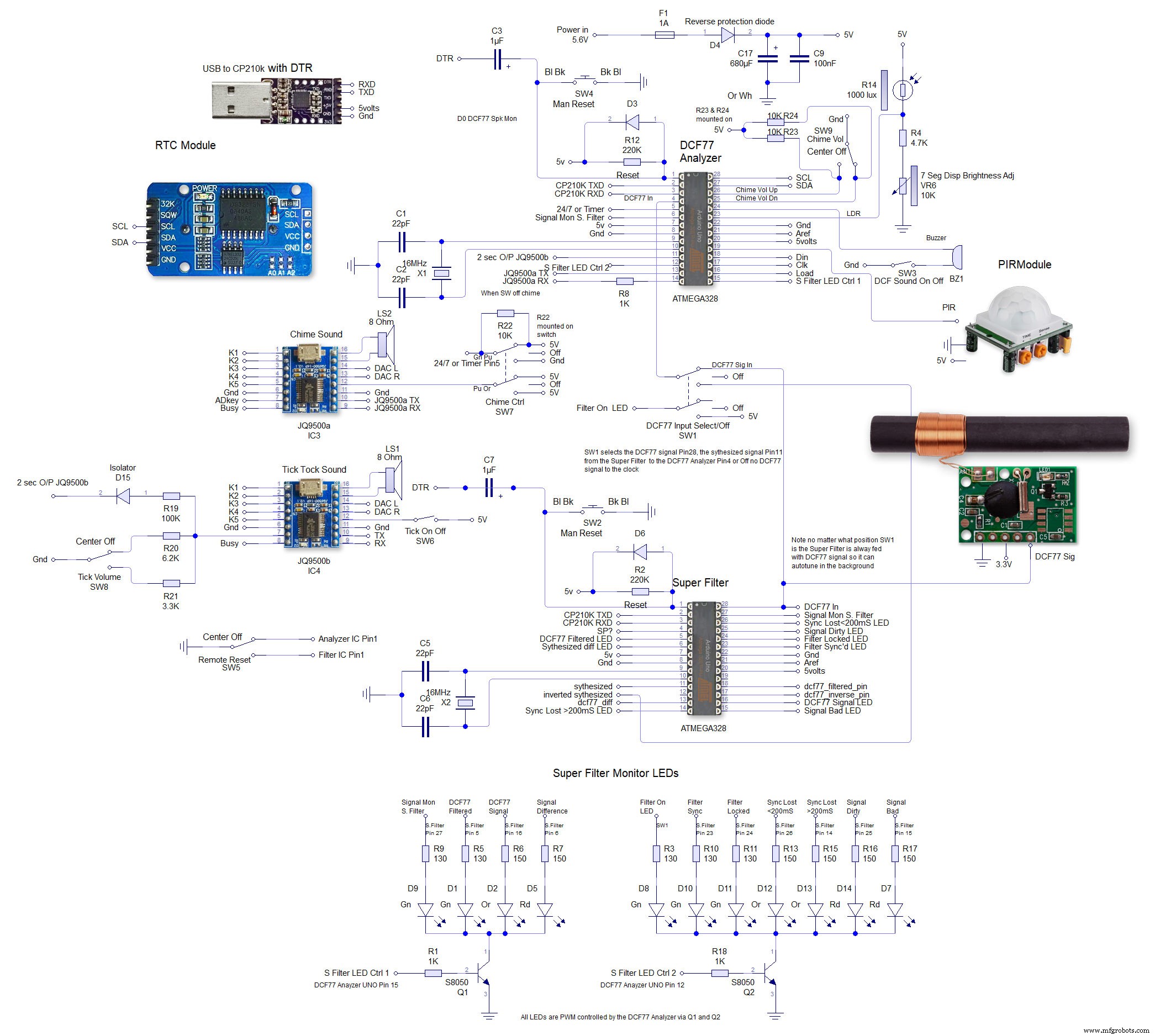 This is the schematic to show the MAX7219 dot matrix module wirng to the LEDs
  This shows the wiring for the MAX7219 7 segment display modules