Tentang proyek ini
Detail lebih lanjut tentang build ini dapat ditemukan di situs saya di sini:Word Clock
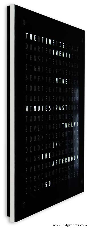
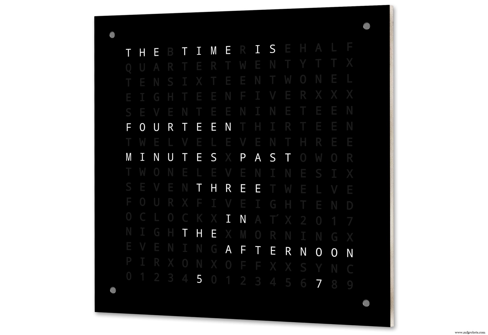
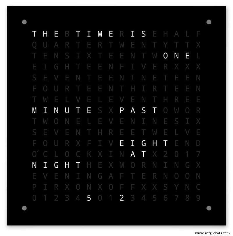
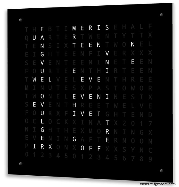
Jam kata Arduino dengan resolusi menit waktu dalam kata-kata dan tampilan linier detik.
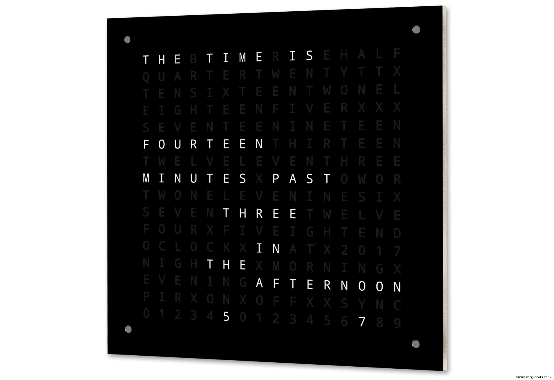
Ada juga mode untuk jam digital, jam analog, suhu dan kelembaban, serta tiga game:Game of Life, Simon dan Tetris.
Jam dapat berdiri sendiri atau dijalankan sebagai budak dari jam master jika diperlukan.
Tanpa jam master, waktu dikendalikan oleh jam real-cime kompensasi suhu bawaan dari jam kata.
Ada pilihan untuk kontrol radar PIR atau doppler sehingga jam otomatis mati saat tidak ada orang di dalam ruangan.
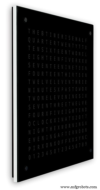
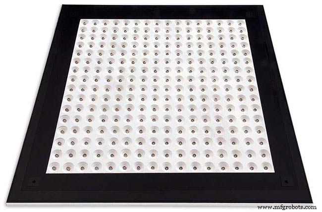
Jam berukuran 500mm x 500mm (19,68" x19,68"), beratnya 12lb (5,5Kg) dan dirancang untuk dipasang di dinding. Ada bantalan sentuh di setiap sudut untuk mengatur dan mengontrol jam.
Langkah 1:Tentang Jam Word
Tentang Jam Kata
Jam kata memberi tahu waktu menggunakan matriks kata atau angka dan huruf dan telah ada selama bertahun-tahun. Ada beberapa jenis desain berbeda yang memengaruhi kerumitan pembuatan jam.
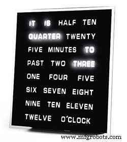
Blok kata yang paling sederhana digunakan untuk memberi tahu waktu dalam resolusi lima menit misalnya O'CLOCK, 5 MAST, 10 MAST, dll. Jam ini hanya menggunakan 20 atau lebih blok LED individual dan oleh karena itu merupakan yang paling sederhana untuk dibuat. Kelemahan utama dari jam ini adalah mereka hanya dapat menunjukkan waktu dalam format set ini.
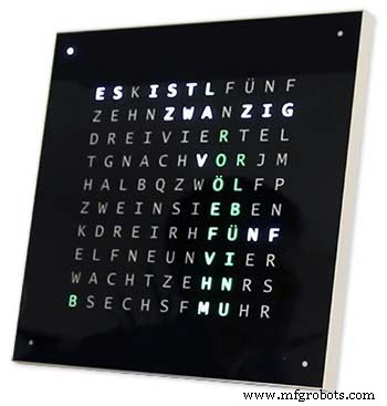
Jam tingkat menengah memiliki matriks LED 11x10 ditambah empat LED tambahan di sekitar bagian luar jam. Jam yang dikontrol Raspberry Pi Foto 2 bahkan memiliki LED warna-warni dan karena memiliki 110 LED individu, jam ini dapat menampilkan angka dan gambar dasar. Jam ini masih menggunakan resolusi 5 menit dalam kata-kata tetapi sering menambahkan "baru saja lewat 5" atau hampir 10 ke" untuk sedikit meningkatkan resolusi. Seringkali empat LED di sekitar sudut bingkai menunjukkan lewatnya empat menit untuk mengisi celah antara resolusi kata 5 menit. Jam ini cukup rumit untuk dibuat dan sering kali menggunakan strip LED untuk mempermudah pembuatan.
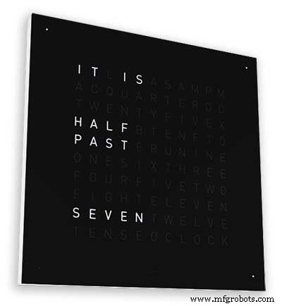
Ada versi komersial dari jam jenis ini yang tersedia. Versi gantung dinding 450mm berharga sekitar £1000 dan menampilkan panel depan yang dapat diganti dalam berbagai warna dan bahan serta desktop dan jam tangan yang lebih kecil tersedia.
256 matrix Word Clock oleh Wouter Devinck
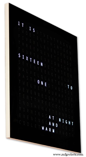
Kata jam dengan tingkat kerumitan tertinggi menggunakan matriks LED 16x16 yang memberikan 256 LED penuh untuk dikontrol. Jam ini memiliki resolusi waktu satu menit serta pagi, sore, malam, dll. Mereka sering memberi tahu suhu kasar dalam kata-kata seperti hangat, sangat hangat, dingin sangat dingin dll.
Dengan 256 LED untuk dimainkan, ada sejumlah besar mode tampilan berbeda yang tersedia. Jam ini cukup rumit untuk dibuat karena jumlah koneksi dalam tampilan matriks. Membangun matriks LED pada PCB dengan komponen pemasangan permukaan memungkinkan badan jam yang sangat ramping dan membuat konstruksi tampilan lebih sederhana tetapi di atas 500mm x 500mm PCB mulai menjadi mahal.
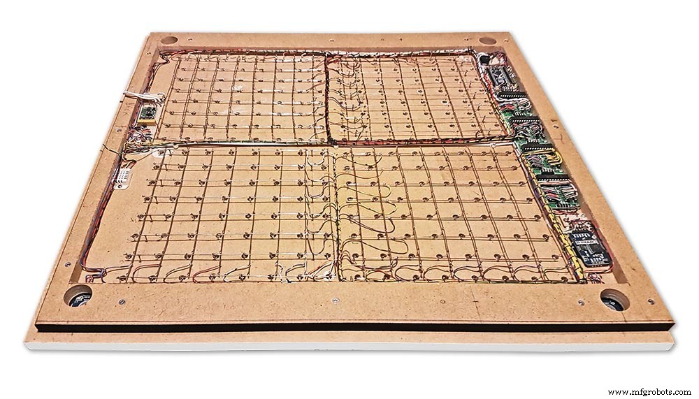
Pembuatan matriks LED seperti pada jam saya membutuhkan ruang dan 500mm x 500mm adalah titik awal yang baik karena ini dapat mengakomodasi alat tenun kabel besar yang diperlukan untuk menghubungkan LED dan modul tampilan. Jam dinding yang sangat besar dapat dibuat menggunakan matriks LED buatan tangan.
Langkah 2:Perubahan 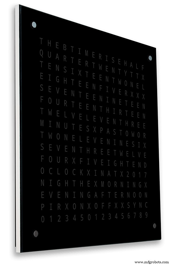
Perubahan
Jam ini adalah campuran dari perangkat keras Jam Wouter Devinck &perangkat lunak jam Pijuana "Catalan". Saya belum pernah menggunakan PCB hanya modul siap pakai dan tiga sirkuit papan Vero kecil untuk daya.
Perubahan utama dirinci di bawah ini.
Tidak ada PCB khusus yang digunakan dalam versi jam ini, hanya saja modul prebuilt yang murah dan mudah didapat.
Badan jam utama dibuat dari 2 x lembar 14 mm MDF, bukan satu lembar 18 mm.
Lembaran belakang 10mm lebih kecil dari lembaran depan di semua sisi kecuali bagian atas sehingga jam tampaknya hanya setebal 14mm.
Jam Wouter Devinck hanya sedalam 20mm termasuk kaca 2mm sedangkan jam saya sebenarnya sedalam 34mm termasuk kaca 4mm dan segel debu 2mm di bagian belakang. Karena kemunduran panel belakang 14mm dan kemunduran panel kaca 1,5mm dari sebagian besar sudut, jam hanya terlihat dalam 14mm. Kedalaman ekstra ini memungkinkan saya untuk menggunakan matriks LED buatan tangan dan alat tenun kabel daripada 4 PCB besar. Ini juga berarti saya dapat menggunakan modul ramah perawatan bawaan tanpa IC pemasangan permukaan pada papan MAX7219.
Tampilan utama dibuat langsung ke LED tampilan tanpa PCB sehingga tampilan ukuran apa pun dimungkinkan. Modul Sensor Sentuh TTP223 digunakan sebagai pengganti Azoteq IQS127D yang dipasang di papan utama.
Papan driver tampilan untuk MAX7219 I/C menggunakan papan matriks LED yang dimodifikasi. Papan ini dilengkapi dengan semua komponen.
Arduino Nano digunakan untuk menggerakkan jam karena ukurannya yang kecil.
Modul sensor PIR digunakan untuk mematikan layar saat tidak ada orang di dalam ruangan (ini dapat dinonaktifkan agar layar selalu menyala).
Sebuah resistor pemangkas ditambahkan ke sirkuit, dapat diakses dari bagian bawah jam dengan obeng pipih kecil untuk mengkalibrasi kecerahan tampilan otomatis.
Sinkronisasi ke sistem jam master saya setiap menit dalam 30 detik. Jika tidak ada pulsa sinkronisasi yang tersedia, jam akan berjalan bebas menggunakan RTC. Pulsa sinkronisasi ditampilkan di layar utama.
Perangkat lunak ini terutama didasarkan pada versi "Catalan" Pijuana dari kata jam jadi ini telah diterjemahkan ke dalam bahasa Inggris untuk tampilan. Tampilan kredit dimodifikasi dari versi "Catalan" Pijuana" untuk menunjukkan nomor versi perangkat lunak saat ini, nama saya dan juga tahun pembuatan.
Kata suhu telah dihapus dari tampilan jam dan tampilan detik linier ditambahkan ke baris bawah jam Word, Digital &Analog.
Ketika PIR dihidupkan atau dimatikan, "PIR ON" atau "PIR OFF" ditampilkan selama beberapa detik pada tampilan jam kata.
Jam ini menggunakan Modul Jam Waktu Nyata Presisi DS3231 AT24C32 I2C sesuai dengan Jam Wouter Devinck &jam Pijuana "Catalan". Saya tidak tertarik menggunakan baterai isi ulang Lithium-Ion yang disertakan dengan modul. Saya menggunakan baterai yang tidak dapat diisi ulang dan telah memodifikasi modul agar sesuai.
Kaca float 4mm dengan tepi yang dipoles menggantikan kaca 2mm. Kaca dipasang ke papan MDF utama menggunakan Pengencang Chicago daripada lem. Ini juga berfungsi sebagai bantalan sentuh untuk mengontrol jam dan memungkinkan kaca dapat dilepas jika diperlukan.
Dua segel debu terpasang pada jam, satu di panel belakang dan satu di belakang panel layar kaca yang dapat dilepas. Dalam mode pengaturan jam, menekan tombol BOT Kanan sekarang mengatur ulang detik ke 0.
Perubahan berikut pada kata-kata bahasa Inggris telah dibuat untuk membuat kata-kata seperti yang akan saya katakan. Cara individu mengatakan waktu akan bervariasi dari satu daerah ke daerah lain tergantung di mana Anda tinggal/sekolah dll dll. Tidak ada cara yang benar hanya cara yang terdengar terbaik untuk Anda.
Menghapus kata-kata yang menunjukkan suhu pada jam kata. Ini telah diganti dengan status sinkronisasi, PIR ON/OFF dan tampilan Linear detik.
Mengubah "MINUTES" menjadi "MINUTE" pada 1 menit berlalu dan 1 menit menjadi satu jam.
Menambahkan "A" sebelum "QUARTER" lewat dan "QUARTER" ke jam.
Menambahkan "ELEVEN" yang hilang dari jam Wouter Devinck sesuai catatannya.
Tengah hari berganti waktu untuk membaca DUA BELAS JAM SIANG.
Pada Midnight mengubah waktu untuk membaca TWELVE OCLOCK AT NIGHT. Setelah Tengah Malam jam akan selalu mengatakan DI PAGI.
"O'CLOCK" sekarang tidak diberi tanda baca dan hanya menunjukkan OCLOCK.
Langkah 3:Desain Kasus 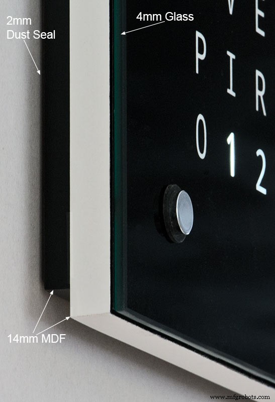
Karena jam saya tidak menggunakan PCB Matriks Tampilan kustom dengan komponen pemasangan permukaan, casing jam saya harus lebih dalam dari desain Wouter.
Kasing saya memiliki kedalaman 34mm dan termasuk segel debu belakang 2mm, papan MDF belakang 14mm, papan display depan 14mm dan kaca float 4mm.
Kanan casing Wouter hanya sedalam 21mm, panel MDF tunggal 18mm, dan kaca pelampung 2mm.
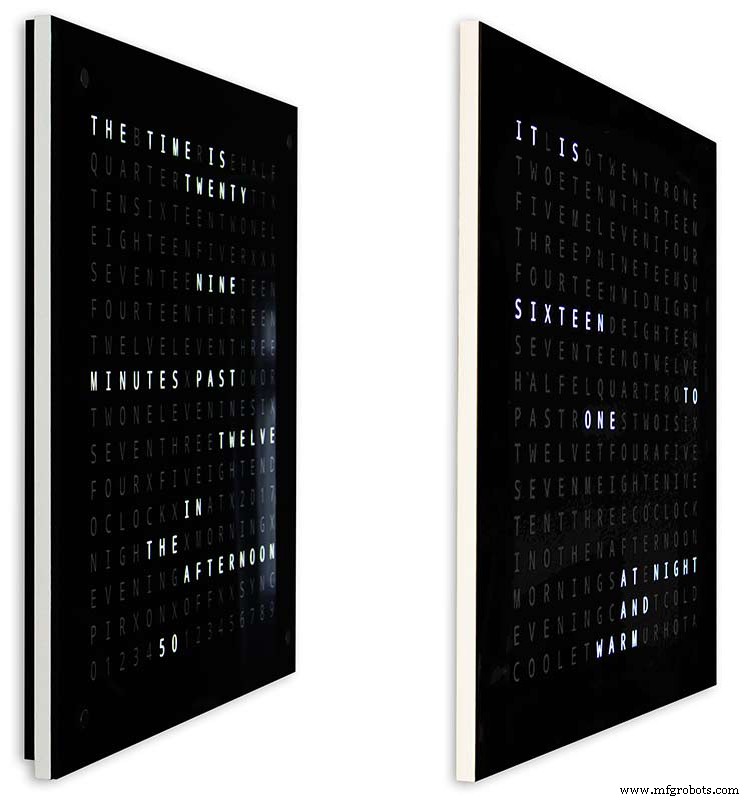
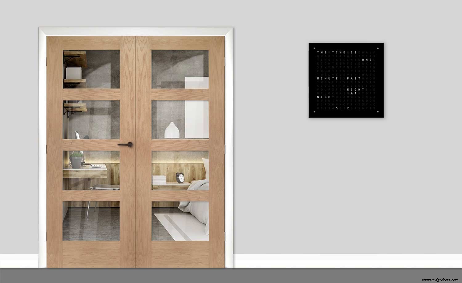
Untuk membuat jam saya terlihat tidak terlalu besar saat dipasang di dinding, saya telah memasukkan beberapa fitur desain sederhana. Pic di atas menunjukkan jam saya di sebelah kiri dan jam Wouter di sebelah kanan. Dari tampilan sudut samping yang ekstrem, Anda dapat dengan jelas melihat kasing saya terlihat lebih besar.
Ini agak diimbangi oleh papan belakang yang berwarna hitam daripada putih membuat mata Anda berkonsentrasi pada tepi 14mm putih tipis. Papan belakang menjadi 10mm lebih pendek di bagian bawah dan kedua sisi memaksakan ilusi ini.
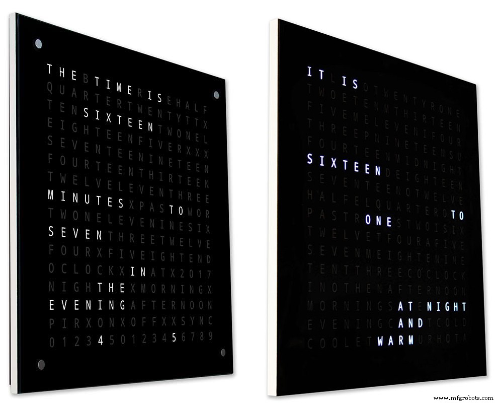
Di atas - lagi jam saya di sebelah kiri dan jam Wouter di sebelah kanan. Semakin jauh ke arah depan jam Anda pergi papan belakang yang lebih pendek pada jam saya menghilang dari pandangan sampai hanya papan depan 14mm tipis yang terlihat. Kaca 4mm juga dipotong 1-2mm lebih pendek dari papan depan membantu menyembunyikannya dari pandangan . Casing jam 34mm saya yang besar sekarang tampak setipis casing Wouter.
Langkah 4:Kontrol
Kontrol

Ada modul kontrol sentuh TTP223 pada jam, kiri atas, kanan atas, kiri bawah, dan sudut kanan bawah layar.
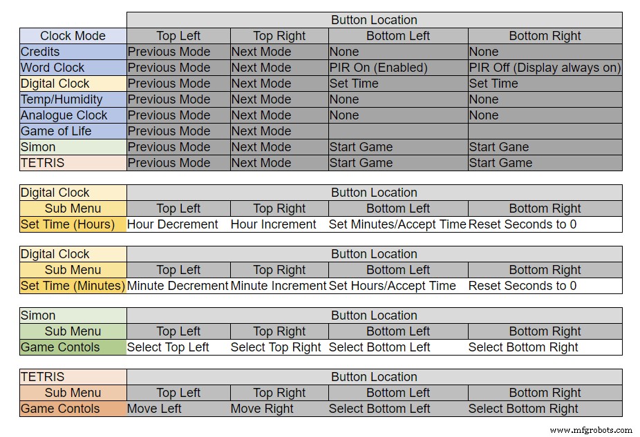
Tombol memiliki fungsi yang berbeda tergantung pada mode jam, lihat tabel di atas.
Langkah 5:Pengaturan Musim Panas Musim Dingin Otomatis
Tidak digunakan.
Langkah 6:Mode Tampilan Jam &Lingkungan 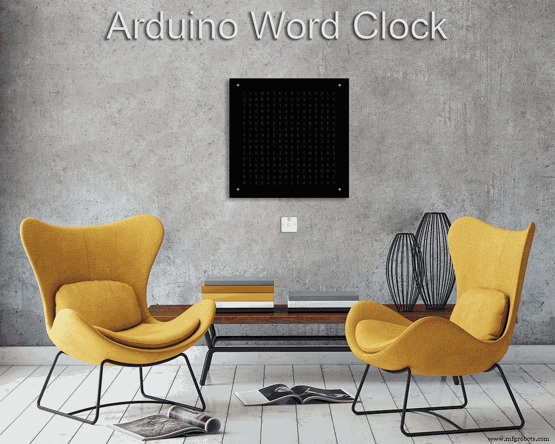
Animasi 1 di atas menunjukkan 4 mode jam dan lingkungan.
Modusnya adalah dalam urutan jam kata, jam digital, suhu dan kelembapan, dan jam analog.
Animasi 2 di atas. Ada juga mode startup yang menggulir nomor versi perangkat lunak, nama pembuat dan nama jam.
Langkah 7:Mode Tampilan Game
Tiga game klasik dikodekan ke dalam jam. Saya telah meninggalkan kode apa adanya dari Jam Catalan.

Animasi 1 di atas Game of Life Conway. Alam semesta Game of Life adalah kotak ortogonal dua dimensi tak terbatas dari sel persegi, yang masing-masing berada di salah satu dari dua kemungkinan keadaan, hidup atau mati, atau "berpenduduk" atau "tidak berpenghuni".
Setiap sel berinteraksi dengan delapan tetangganya, yaitu sel-sel yang berdekatan secara horizontal, vertikal, atau diagonal. Pada setiap langkah waktu, transisi berikut terjadi:Setiap sel hidup dengan kurang dari dua tetangga hidup mati, seolah-olah disebabkan oleh populasi yang kurang. Setiap sel hidup dengan dua atau tiga tetangga hidup akan terus hidup ke generasi berikutnya. Setiap sel hidup dengan lebih dari tiga tetangga hidup mati, seolah-olah karena kelebihan populasi. Setiap sel mati dengan tepat tiga tetangga hidup menjadi sel hidup, seolah-olah dengan reproduksi.
Pola awal merupakan benih dari sistem. Generasi pertama dibuat dengan menerapkan aturan di atas secara bersamaan untuk setiap sel dalam benih kelahiran dan kematian terjadi secara bersamaan, dan momen diskrit di mana hal ini terjadi kadang-kadang disebut kutu (dengan kata lain, setiap generasi adalah fungsi murni dari generasi sebelumnya. satu). Aturan terus diterapkan berulang kali untuk menciptakan generasi selanjutnya.
Animasi 2 di atas Simon
Permainan memori Simon- coba dan salin urutan yang dihasilkan komputer. Saat memasukkan urutan Anda, ketuk dua kali entri terakhir untuk mengakhiri giliran Anda.
Ketika Anda gagal, skor Anda ditampilkan di layar.
Animasi 3 di atas TetrisTetris adalah video game teka-teki pencocokan ubin Soviet yang dirilis pada Juni 1984. Gim ini masih memerlukan beberapa perbaikan pada tombol untuk mengontrol ubin dengan benar.
Langkah 8:Membuat prototipe
Jam dapat dibuat prototipe dan diuji menggunakan LED Matrix DOT asli pada papan tampilan MAX7219.
Perhatikan bahwa modifikasi sementara ini hanya diperlukan jika Anda ingin menguji kode Anda pada tampilan matriks DOT yang disertakan dengan modul MAX7219.
Ini berarti Anda dapat mencoba modifikasi tata letak perangkat lunak/kata Anda dalam bentuk mini sebelum melakukan versi ukuran penuh. Pengkabelan ke LED Matrix DOT harus dimodifikasi agar sesuai dengan koneksi perangkat lunak.
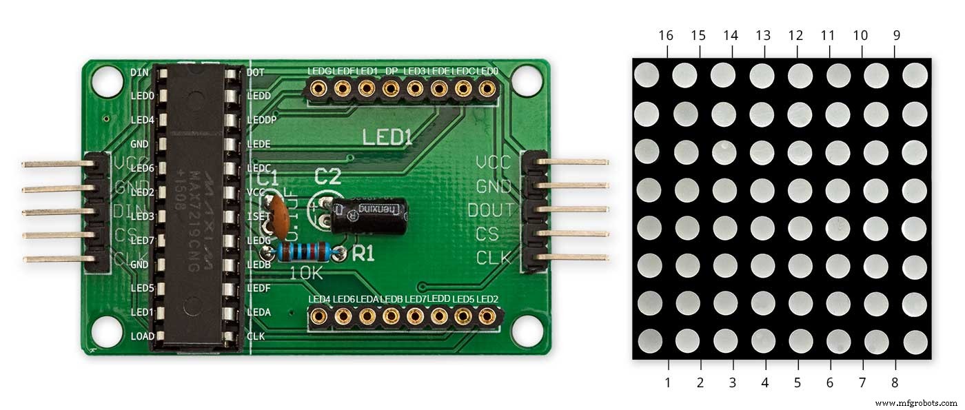
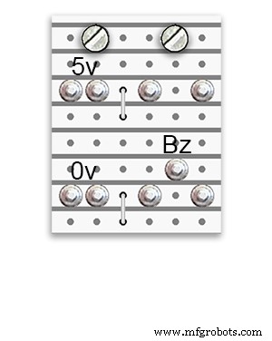
Gambar di atas menunjukkan bagaimana Modul disambungkan sebelum dimodifikasi. Modifikasinya cukup lurus ke depan. Pertama-tama tekuk pin Matrix LED berikut 90°, pin atas ke atas dan pin bawah ke bawah.
Pin 16, 15, 3, 4, 10 &11.
Masukkan Matriks LED ke soket pada tampilan PCB, pin di atas sekarang tidak akan terhubung. Solder kabel tautan berikut dari bagian belakang soket PCB tampilan ke pin Matriks LED yang mencuat.
LEDA ke Dot Matrix Pin 16
LEDB ke Dot Matrix Pin 15
LEDG ke Dot Matrix Pin 3
LEDF ke Dot Matrix Pin 4
LEDE ke Dot Matrix Pin 10
LEDC ke Dot Matrix Pin 11
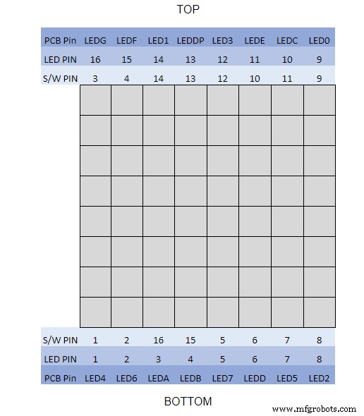
Saya menggunakan multimeter dan mengeluarkan modul tampilan. Tabel menunjukkan di mana nomor pin perangkat lunak berbeda dari nomor pin LED pada papan tampilan.
Untuk menguji tata letak kata Anda, cetak versi mini tampilan kata Anda 62mm x 62mm di atas kertas putih biasa.
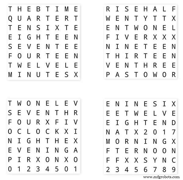
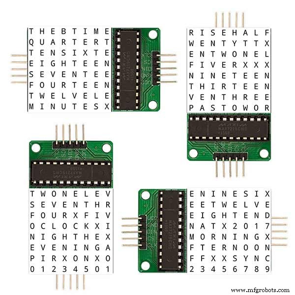
Perhatikan orientasi papan Tampilan LED agar sesuai dengan tata letak perangkat lunak.
Saya telah mempertahankan rotasi tampilan sebagai jam Wouter Devinck asli jika ada yang menggunakan desain PCB Wouter Devinck untuk jam saya.
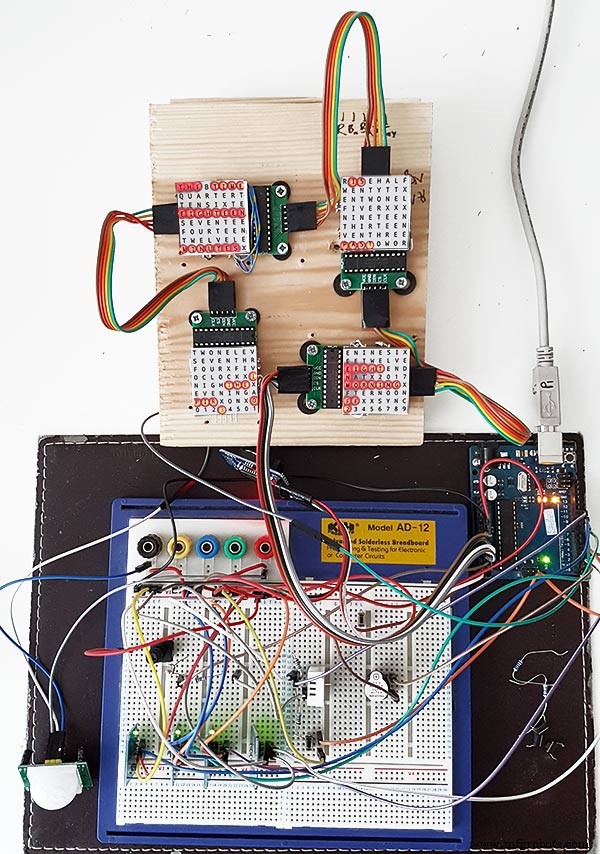
Tombol tekan kecil di bawah sensor suhu/kelembaban digunakan untuk menguji sinkronisasi 30 detik. Modul tombol sentuh berada di kiri bawah papan tempat memotong roti yang dipasang menyamping. Tidak banyak kabel pada prototipe ini karena sebagian besar kabel ada di matriks tampilan. Pada jam terakhir, pengkabelan ini akan dilakukan dengan tangan ke masing-masing LED.
Saya mencoba banyak desain kata/jam yang berbeda di papan ini sebelum mencoba membuat jam terakhir.
Langkah 9:Menguji Modul yang Dimodifikasi 
Saya telah memodifikasi sketsa jam kata untuk mengaktifkan modul MAX2719 yang akan diuji setelah mod pengkabelan.
Semua program ini id menyalakan setiap LED secara bergantian dari kiri atas ke kanan bawah matriks.
Cukup sambungkan 5 kabel ke modul NANO dan MAX2719 dan nyalakan NANO dari port USB-nya. Muat sketsa dan biarkan berjalan.
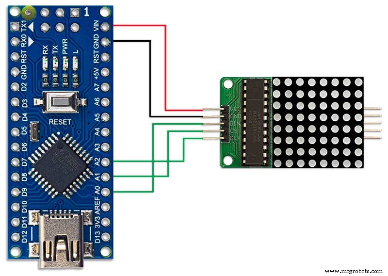
Cukup colokkan setiap modul secara bergantian untuk memeriksa kabel Anda.
Unduh sketsa pengujian dari file zip terlampir.
MAX7219_LED_Test.zip
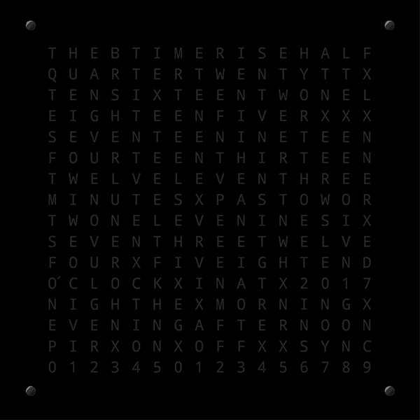
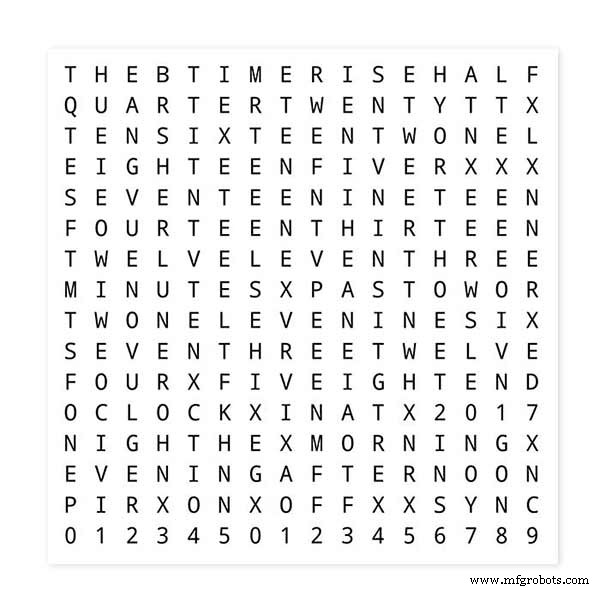
Langkah 10:Saatnya Pemetaan Kata 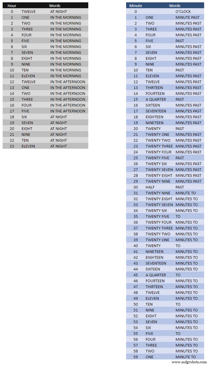
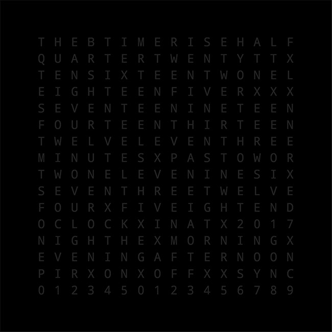
Tabel di atas menunjukkan Time to Word Mapping.
Tidak ada aturan keras dan cepat tentang ini, cukup atur kata-kata seperti yang Anda katakan pada waktu.
Di jam saya, saya mengubah yang berikut ini dibandingkan dengan kata-kata di jam Wouter.
"MINUTES" diubah menjadi "MINUTE" pada 1 menit berlalu dan 1 menit menuju jam. Menambahkan "A" sebelum "QUARTER" melewati dan "QUARTER" ke jam.
Tengah hari berganti waktu untuk membaca DUA BELAS JAM SIANG.
At Midnight mengubah waktu untuk membaca DUA BELAS JAM DI MALAM.
Setelah Tengah Malam, jam akan selalu menunjukkan DI PAGI.
Perubahan ini sangat mudah diterapkan dalam perangkat lunak jam.
Word%2Bto%2BTime%2BTranslations.xlsx
Langkah 11:Daya 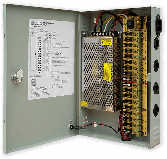
Saya menggunakan unit catu daya 12 volt yang umum untuk menggerakkan berbagai jenis sirkuit di seluruh rumah saya. Suplai 12 volt ini kemudian diturunkan secara lokal di setiap sirkuit dengan modul 5 volt untuk memasok daya ke papan kontrol dan berbagai modul.
Catu daya umum saya memiliki 18 sirkuit 12v yang menyatu secara individual masing-masing dengan sekering 2A. 9 di antaranya adalah baterai yang didukung. Papan jam juga memiliki sekering sendiri.
Jika Anda hanya menjalankan sirkuit yang satu ini, maka suplai 5 volt yang diatur akan berfungsi selama dapat memasok arus untuk penggunaan sirkuit Anda.
Saya telah merancang papan daya pada Vero yang menggunakan catu daya mini MP1584. Ini mengubah output 12v dari catu daya umum saya ke 5v untuk jam.
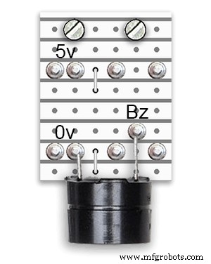
Ada dua papan daya tambahan yang dibuat dari papan Vero.
Selain 1 menahan bel, mereka hanya menambahkan titik distribusi daya ekstra untuk kabel daya jam.
Persyaratan Daya
Saya telah mengukur penarikan arus dari jam dan pada kecerahan rendah menggunakan 30mA dan kecerahan penuh 250mA. Ini tentu saja akan bervariasi dengan berapa banyak LED yang menyala. Pada hari yang cerah, tingkat kecerahan yang ditunjukkan pada serial out adalah 10. Ini sekitar 2 pertiga dari daya maksimum LED. Konsumsi daya secara keseluruhan dapat sangat berkurang jika PIR dihidupkan. Ini akan mengosongkan tampilan jika gerakan tidak terdeteksi oleh jam.
Saya akan menggunakan suplai minimum 500mA untuk menyalakan jam. Daya akan sangat bergantung pada jenis LED yang Anda sumber.
Langkah 12:Interkoneksi Modul
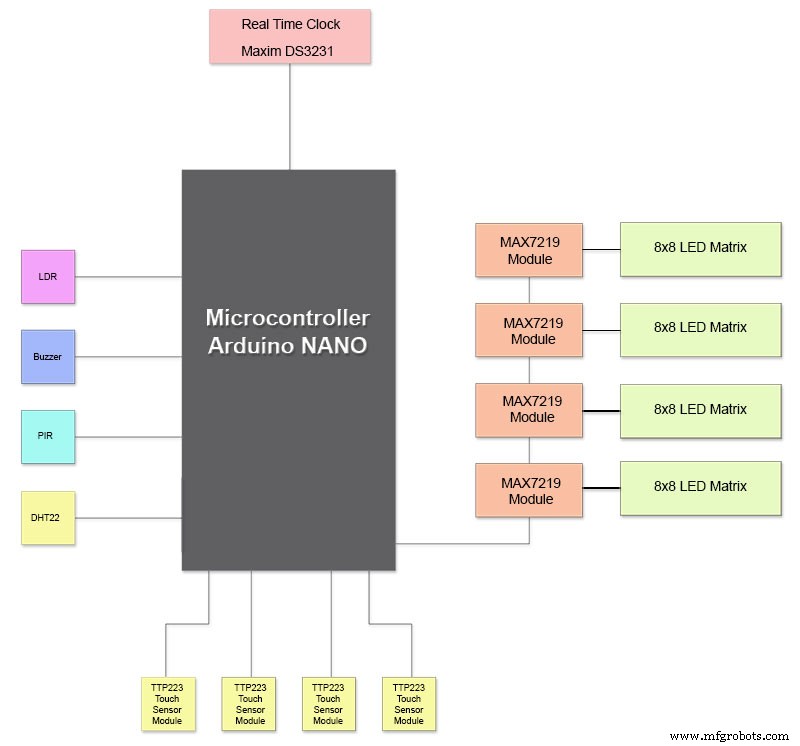
Pic di atas menunjukkan bagaimana modul terhubung. Sebagian besar modul terhubung langsung ke Arduino Nano.
Papan MAX7219 hanya terhubung ke NANO melalui modul 01. Modul lainnya dirangkai bersama.
Setiap matriks LED 8x8 kemudian dihubungkan ke modul MAX7219.
Sebagian besar kabel adalah koneksi antara modul MAX7219 dan matriks LED.
Jaga jarak antara modul NANO dan 1 MAX7219 dan modul MAX7219 ke modul sesingkat mungkin. Pastikan juga Anda memasok daya ke kedua ujung daisy chain MAX7219 karena sebagian besar daya diambil oleh bagian sirkuit ini.
Langkah 13:Urutan Konstruksi Bangunan
Urutan pembuatan dengan asumsi semua pembuatan prototipe dan perubahan perangkat lunak diselesaikan terlebih dahulu.
Cetak transfer vinyl.
Dapatkan potongan kaca.
Potong Lembar MDF depan dan belakang.
Potong lubang di lembaran depan untuk LED.
Cat Lembar MDF.
Potong lubang untuk sensor di kaca.
Tempelkan transfer Vinyl ke bagian belakang kaca.
Potong lubang sensor di papan depan MDF.
Potong rabat modul sensor di papan depan.
Potong papan belakang MDF dan buat 4 lubang akses untuk akses sensor.
Tambahkan strip tepi melamin ke papan MDF, putih ke papan depan dan hitam ke papan belakang.
Pasang kembali papan MDF ke papan MDF depan.
Buat papan Vero, 1 papan daya, dan 2 papan distribusi daya.
Ubah papan 4 x MAX7219 dan tambahkan kabel ke LED.
Sambungkan di MAX7219 end hanya untuk saat ini.
Pasang semua modul dan papan Vero di bagian belakang papan depan MDF.
Bangun semua 4 matriks LED di papan MDF depan dan solder 256 LED.
Hubungkan semua Batt dan Earth berjalan dari papan Vero catu daya dan papan distribusi daya.
Hubungkan semua power run ke semua modul.
Hubungkan semua kabel ke Nano, modul MAX7219, RTC, Sensor suhu, Sensor Sentuh, dan Buzzer.
Hubungkan semua alat tenun kabel dari papan MAX7219 yang dimodifikasi ke Matriks LED sesuai tabel kabel.
Hubungkan modul PIR dari jarak jauh dari jam dan hubungkan koneksi PIR.
Hubungkan sinkronisasi 30 detik ke Jam Master Anda (jika diperlukan).
Pasang panel tampilan depan Kaca menggunakan baut Chicago yang juga memasang sensor sentuh secara bersamaan.
Uji.
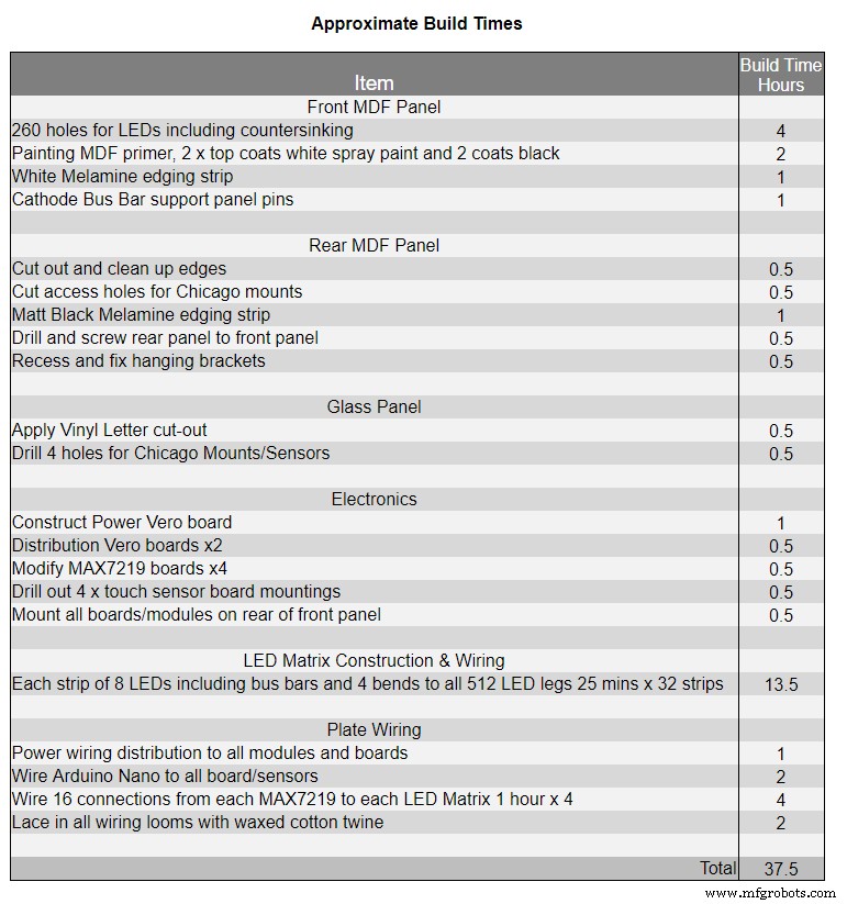
Tabel 1 menunjukkan perkiraan waktu pembuatan untuk jam ini dan akan bervariasi tergantung pada tingkat keahlian Anda dan juga alat khusus/ruang kerja yang harus Anda miliki.
Anda dapat dengan mudah menambahkan 40 jam waktu pembuatan prototipe dan pemrograman ke daftar itu.
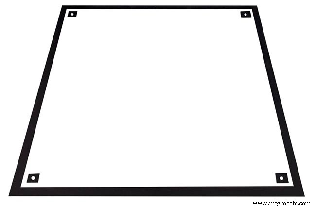
Langkah 14:Konstruksi Stiker Vinil
Stiker Vinil
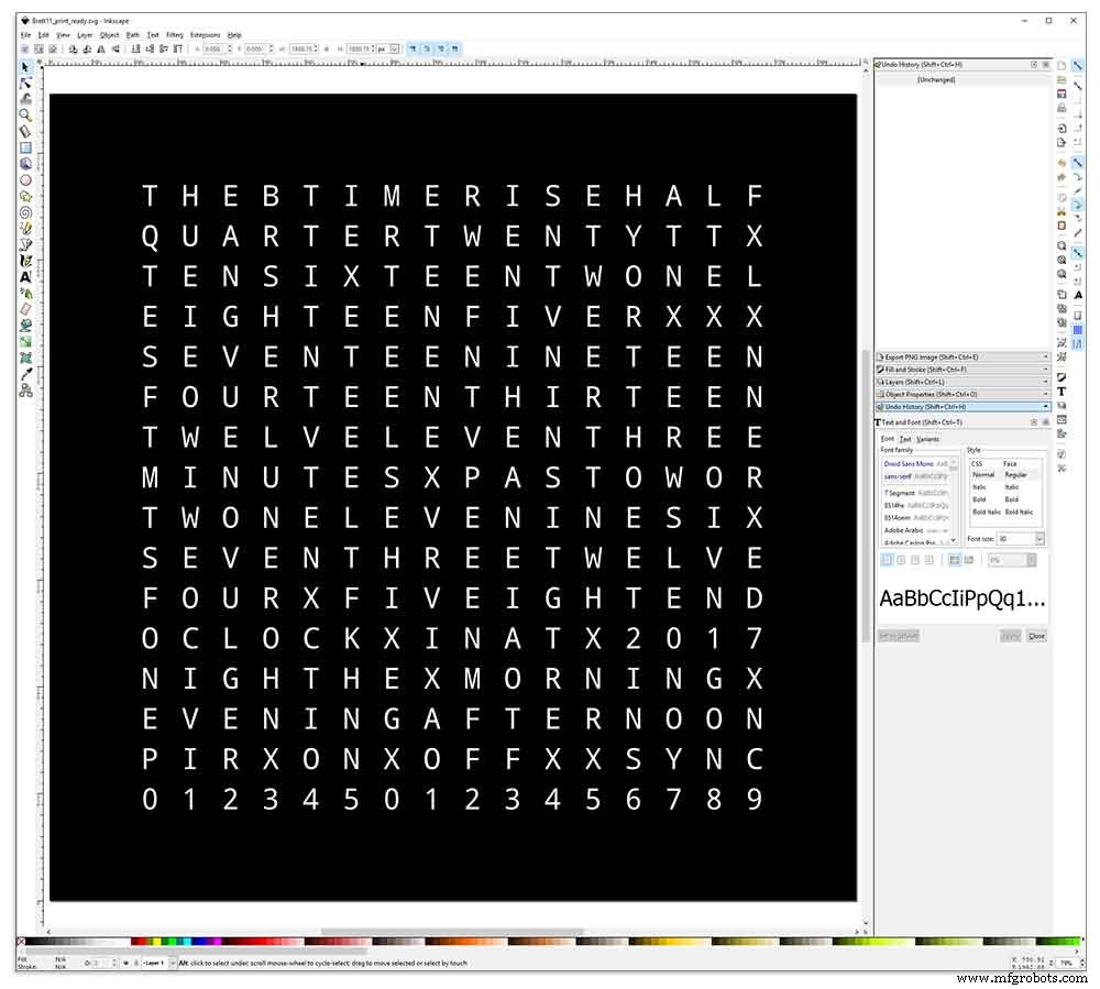
Stiker Vinyl dirancang dalam Inkscape.
Inkscape adalah perangkat lunak grafis vektor berkualitas profesional yang berjalan di Windows, Mac OS X dan GNU/Linux. Ini digunakan oleh para profesional desain dan penghobi di seluruh dunia untuk membuat berbagai macam grafik seperti ilustrasi, ikon, logo, diagram, peta, dan grafik web.
Inkscape menggunakan SVG standar terbuka W3C (Scalable Vector Graphics) sebagai format aslinya, dan merupakan perangkat lunak sumber terbuka dan gratis.
Saya mengunduh desain Inkscape asli oleh Wouter Devinck dari repositori GitHub-nya dan kemudian memodifikasinya di Inkscape agar sesuai dengan desain saya. Saya mencoba banyak versi berbeda pada prototipe miniatur saya sebelum mengirimkan desain akhir untuk dicetak.
Jangan lupa untuk mencetak stiker terbalik!
Saya menggunakan perusahaan bernama Regal Signs &Graphics yang memasok stiker saya dalam vinil hitam, potongan terbalik, huruf disingkirkan dan dilengkapi dengan pita aplikasi semuanya seharga sekitar £ 27 termasuk tong.
Meskipun mereka cukup lokal bagi saya, saya membayar sedikit lebih banyak dan stiker saya dikirim dalam tabung karton yang bagus dan aman.
Saya memiliki beberapa masalah dalam mendapatkan desain dalam format yang benar untuk mesin mereka, tetapi pada akhirnya saya mengirimnya dari Illustrator dalam format eps, orang-orang yang sangat membantu di Regal Signs menurunkannya ke ukuran yang benar untuk saya. File Inkscape saya dapat diunduh di sini STIKER VINYL.
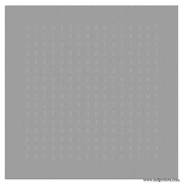
Stiker Vinyl berasal dari Regal Signs dengan huruf-huruf yang dihilangkan sehingga ini menghemat banyak waktu. Stiker dilengkapi dengan pita plastik di sisi depan (kaca) dan kertas aplikasi di bagian belakang. Biasanya Anda mengupas selotip dari samping menerapkan stiker dan kemudian menghapus kertas aplikasi. Saya memutuskan untuk meninggalkan kertas aplikasi karena berfungsi sebagai diffuser untuk LED. Saat saya meninggalkan kertas aplikasi, saya memangkas sisa kertas di sekitar stiker sebelum melamar.
Aplikasi stiker pun relatif mudah. Pastikan Anda menonton beberapa video YouTube di aplikasi stiker Vinyl ke kaca sebelum mencobanya sendiri.
Kaca

Jam menggunakan kaca float 4mm dan telah dipotong menjadi 500mm x500mm. Karena tepinya terbuka, tepinya juga telah dipoles. Ini semua dilakukan oleh tukang kaca lokal saya seharga £20.
Lubang 5mm kemudian dibor di panel kaca menggunakan bor kaca 5mm. Lihat video YouTube tentang cara mengebor lubang di kaca.
Saya membersihkan kaca terlebih dahulu dengan aseton dan memastikannya bebas debu (sangat penting). Saya kemudian memakai beberapa sarung tangan plastik untuk memastikan saya tidak mendapatkan sidik jari pada stiker.
Saya menyemprot kaca dengan campuran sabun dan air yang sangat encer, lalu perlahan-lahan mengupas film plastik dari stiker untuk memperlihatkan permukaan depannya.
Penting untuk mengupas film kembali secara perlahan dan pada sudut yang sangat tajam sehingga huruf-huruf pada stiker tetap terhubung dengan kertas transfer. Setelah stiker benar-benar terbuka, oleskan ke permukaan kaca yang basah.
Campuran air/sabun akan memungkinkan Anda untuk memindahkan stiker ke tempat yang benar pada kaca. Selanjutnya gunakan kartu kredit dan jauhkan dari bagian tengah stiker untuk menghilangkan gelembung udara. Biarkan stiker mengering semalaman, lalu dari bagian belakang stiker potong vinil di atas 4 lubang pemasangan di kaca.
Brett11_print_ready.svg
Langkah 15:Konstruksi Papan Utama Bagian 1
Papan Utama
Papan utama jam terdiri dari 2 lembar 14mm MDF. Lembaran belakang 10mm lebih kecil dari lembaran atas di semua sisi selain dari atas. Bagian atas memiliki tepi putih sedangkan bagian belakang memiliki tepi hitam. Saat dilihat di dinding, jam akan tampak sedalam 14 mm.
Papan utama jam terdiri dari 2 lembar 14mm MDF. Lembaran belakang 10mm lebih kecil dari lembaran atas di semua sisi selain dari atas. Bagian atas memiliki tepi putih sedangkan bagian belakang memiliki tepi hitam. Saat dilihat di dinding, jam akan tampak sedalam 14mm.
Pada Jam Wouter Devinck asli &versi Pijuana "Catalan" satu lembar MDF setebal 18mm digunakan dengan bagian belakang dirutekan untuk memberi ruang bagi PCB dan komponen. Menggunakan 2 lembar MDF berarti papan belakang dapat dengan mudah dipotong menggunakan gergaji ukir daripada perutean yang memakan waktu dan berdebu. Lembaran atas berukuran 503mm x 503mm untuk memberikan tumpang tindih 1,5mm di sekitar kaca. Ini akan memberi kaca sedikit perlindungan dari benturan.

Papan belakang dipotong menggunakan gergaji ukir dan memungkinkan ruang komponen 14mm.
PCB terdalam termasuk komponen adalah modul MAX 7219 dengan kedalaman 10mm. Setelah selesai, papan belakang direkatkan atau disekrup ke papan depan.
Konstruksi Papan Depan
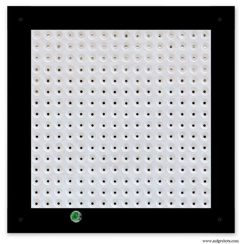
Papan depan memegang 256 LED yang bersinar melalui lubang 6,5 mm dan lubang countersunk 18 mm yang lebih lebar untuk menerangi huruf dan angka individual pada layar.
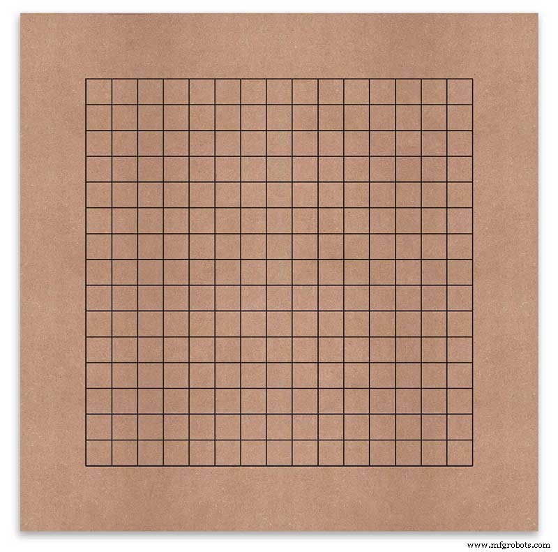
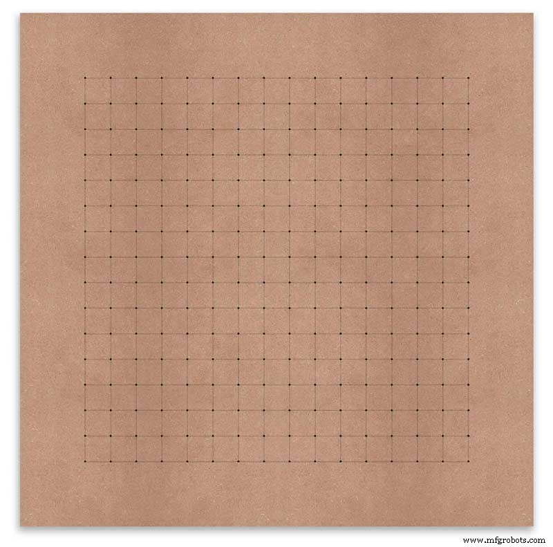
Papan ditandai untuk menunjukkan posisi pengeboran di tengah setiap karakter tampilan. Menggunakan layar 500mm, saya mengukur lembaran vinil saya dan karakternya terpisah 25mm mulai 62,5mm dari tepinya. Saya menggambar garis-garis ini di MDF, persimpangan menjadi titik pengeboran.
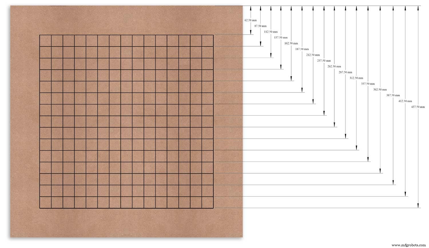
Saya menggunakan tepi atas sebagai titik datum yang saya ukur dan tandai setiap baris dari titik ini.
Ini diulang untuk kolom vertikal menggunakan tepi kiri sebagai datum.
Perpotongan kisi-kisi akan menjadi titik tengah untuk lubang pemasangan LED 6mm dan lubang countersunk 18mm.
Using an automatic centre punch ( use a nail or screw if you don't have one) I punched the 256 intersection points of the grid.
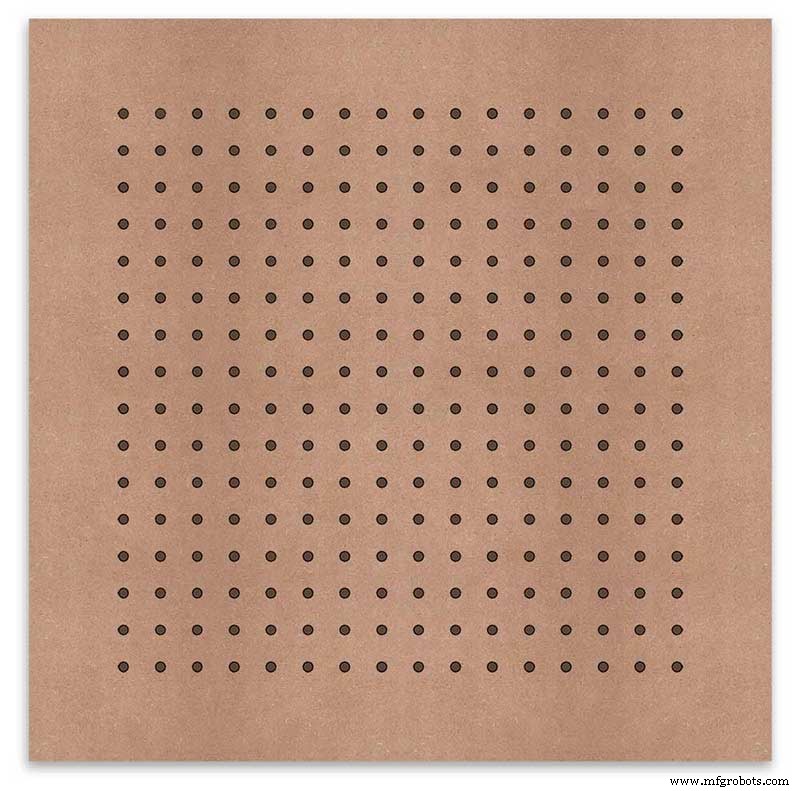
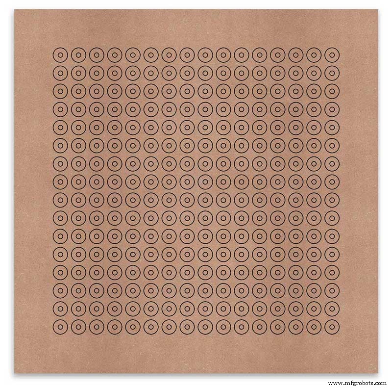
Using a drill bit to suite your LEDs (6mm in my case) and using the punched holes as a guide for the drill bit drill out all 256 LED mounting holes.
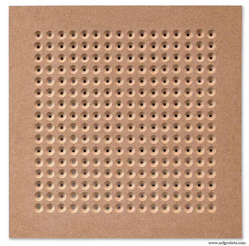
The next task is to drill the 256 18mm countersunk holes using a 20mm countersinking bit.
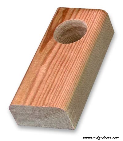
To keep the countersunk holes at a uniform depth and width I built a countersinking jig using an off cut of wood. To make the jig a hole is drilled in the wood off cut to just fit the silver rotating bezel of my drill chuck. Using a test piece of MDF the countersinking bit is then moved in and out of the chuck until a countersunk hole of the correct diameter is made when drilling through the hole upto the chuck in the off cut of wood. Once the correct distance is found the chuck is tightened and the main board is drilled 256 times by centring the hole in the wood over the existing 6mm holes then drilling down until the chuck bezel hits the hole in the countersinking jig.
Completed front board with 256 countersunk holes and 6mm holes for the LEDs.
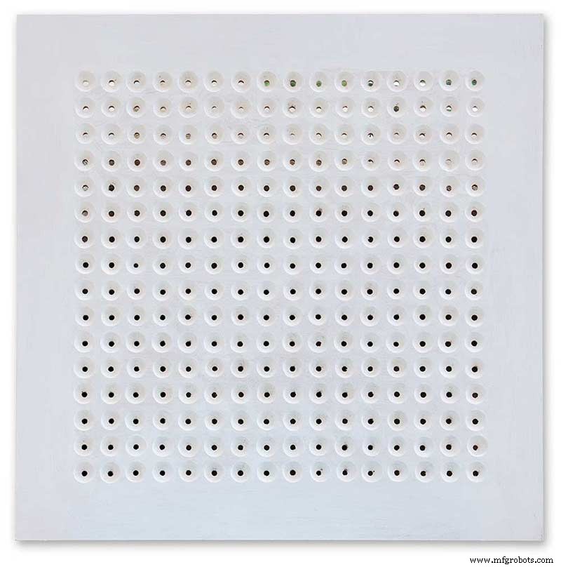
The board is then rubbed down and primed using MDF primer and painted white so the countersunk holes reflect the light from the LEDs.
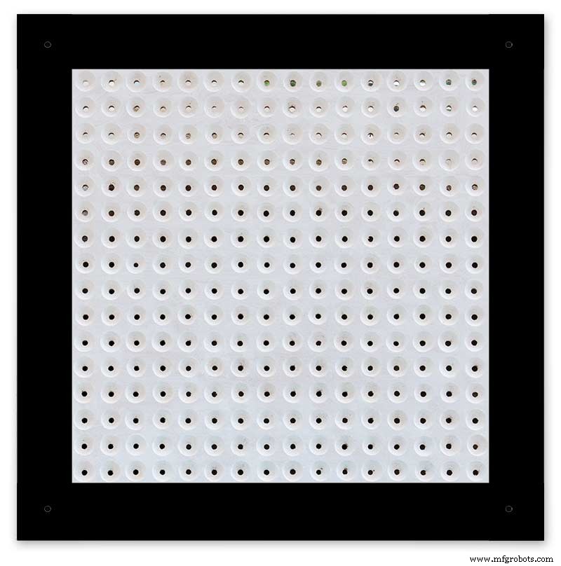
A black edge is painted around the outside edge to hide the board as the glass is 1mm shorter all round. This setback also helps the glass disappear from view on the final clock.
Four 5mm holes are then drilled in the corners to take the Chicago Fasteners. The Chicago Fasteners hold the glass in place, hold the touch sensors and provide a touch sensitive pad on top of the glass. The fasteners have 3mm shafts and will have a small bit of rubber tape wrapped around the shafts to protect the glass.
Turn the board over and drill a rebate with a forstner bit to take the four touch sensors. This hole will be offset from the hole drilled in the previous step.
Wall Mounts
The clock is fixed to the wall by two metal picture hanging mounts.
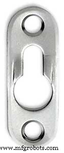
These are recessed into the frame so the highest point of the bracket is level with the frame.
Two 2" countersunk No6 screws sit in these bracket and hold the clock to the wall with a bit of tension so the dust seal is compressed.
Step 16:Construction Touch Sensor Mounting
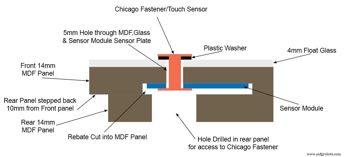
The touch sensor modules are fixed to the front panel using the Chicago Fastener bolts. The Chicago Fastener bolts then act as touch sensors.
A 5mm hole is drilled through the sensor pad on the module to allow the Chicago Fastener bolt to pass through.

The sensor pad is insulated by the MDF panel and a plastic washer.
The touch pad on the sensor module has a 5mm mounting hole drill through the sensor.

Touch sensors in rebates behind rear panel. Holes drilled into rear panel allows access to the Chicago Fasteners that hold the sensors/glass front in place.
Clock front panel with four Chicago Fastener tops acting as touch plates.
Step 17:Electronic Components &Modules 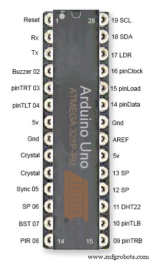
ATmega328 pin connections in case you want to prototype the circuit on an Arduino Uno. Note BST pin 07 is not used.
Pin label numbers refer to Arduino IDE numbers.
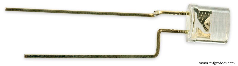
LEDs
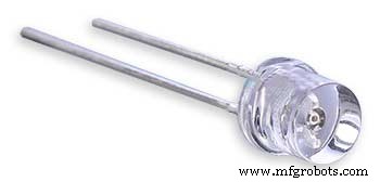
Make sure you purchase your LEDs from a good source. These LEDs will be on for many hours a day. I have has problems with LEDs failing after a few weeks use.
My LEDs Specs
5mm White Flat Top LEDs offering a pure and consistent colour with a wide angle ultra bright light output.
Colour :White
Quantity :256
Lenses Type :Round Flat Top
Crystal ClearBrightness :13000mcdForward
Voltage :3.2v - 3.8v
Forward Current :20mA (typical), 30mA (Max)
Viewing Angle :120 degrees
DHT22 Temperature &Humidity Sensor
The DHT22 is a basic, low-cost digital temperature and humidity sensor. It uses a capacitive humidity sensor and a thermistor to measure the surrounding air, and sends out a digital signal on the data pin.
You can only get new data from it once every 2 seconds, so sensor readings can be up to 2 seconds old.
Simply connect the first pin on the left to 3-5V power, the second pin to your data input pin and the right most pin to ground.
To prevent the temperature of the inside clock case being measured the top and left side vent of the DH22 are covered over with tape. This also stops dust being drawn into the clock case.
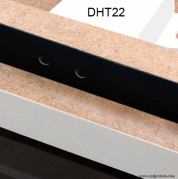
The DHT22 is mounted with its right open side mounted tight against the lower rear cover.Two small holes are drilled in the lower edge of the rear MDF board to allow air from the room to circulate around the sensor.
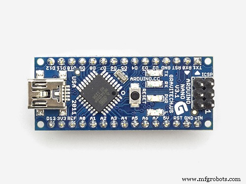
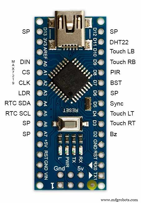
Arduino NANO
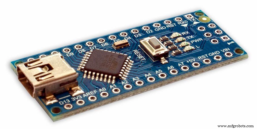
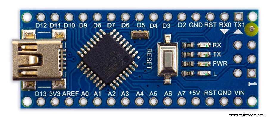
PowerThe Arduino Nano can be powered via the Mini-B USB connection, 6-20V unregulated external power supply (pin 30), or 5V regulated external power supply (pin 27). The power source is automatically selected to the highest voltage source.
Memory
The ATmega328 has 32 KB, (also with 2 KB used for the bootloader.
The ATmega328 has 2 KB of SRAM and 1 KB of EEPROM.
Input and Output
Each of the 14 digital pins on the Nano can be used as an input or output, using pinMode(), digitalWrite(), and digitalRead() functions. They operate at 5 volts. Each pin can provide or receive a maximum of 40 mA and has an internal pull-up resistor (disconnected by default) of 20-50 kOhms. In addition, some pins have specialized functions:Serial:0 (RX) and 1 (TX). Used to receive (RX) and transmit (TX) TTL serial data. These pins are connected to the corresponding pins of the FTDI USB-to-TTL Serial chip.
External Interrupts:2 and 3.
These pins can be configured to trigger an interrupt on a low value, a rising or falling edge, or a change in value. See the attachInterrupt() function for details.
PWM:3, 5, 6, 9, 10, and 11. Provide 8-bit PWM output with the analogWrite() function.
SPI:10 (SS), 11 (MOSI), 12 (MISO), 13 (SCK). These pins support SPI communication, which, although provided by the underlying hardware, is not currently included in the Arduino language.
LED:13. There is a built-in LED connected to digital pin 13. When the pin is HIGH value, the LED is on, when the pin is LOW, it's off.
The Nano has 8 analog inputs, each of which provide 10 bits of resolution (i.e. 1024 different values). By default they measure from ground to 5 volts, though is it possible to change the upper end of their range using the analogReference() function. Analog pins 6 and 7 cannot be used as digital pins. Additionally, some pins have specialized functionality:I2C:4 (SDA) and 5 (SCL). Support I2C (TWI) communication using the Wire library (documentation on the Wiring website).
There are a couple of other pins on the board:AREF. Reference voltage for the analog inputs. Used with analogReference(). Reset. Bring this line LOW to reset the microcontroller. Typically used to add a reset button to shields which block the one on the board.
Communication The Arduino Nano has a number of facilities for communicating with a computer, another Arduino, or other microcontrollers. The ATmega328 provide UART TTL (5V) serial communication, which is available on digital pins 0 (RX) and 1 (TX). An FTDI FT232RL on the board channels this serial communication over USB and the FTDI drivers (included with the Arduino software) provide a virtual com port to software on the computer. The Arduino software includes a serial monitor which allows simple textual data to be sent to and from the Arduino board. The RX and TX LEDs on the board will flash when data is being transmitted via the FTDI chip and USB connection to the computer (but not for serial communication on pins 0 and 1). A SoftwareSerial library allows for serial communication on any of the Nano's digital pins. The ATmega328 also support I2C (TWI) and SPI communication. The Arduino software includes a Wire library to simplify use of the I2C bus. To use the SPI communication, please see ATmega328 datasheet.
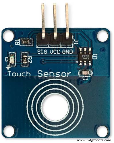
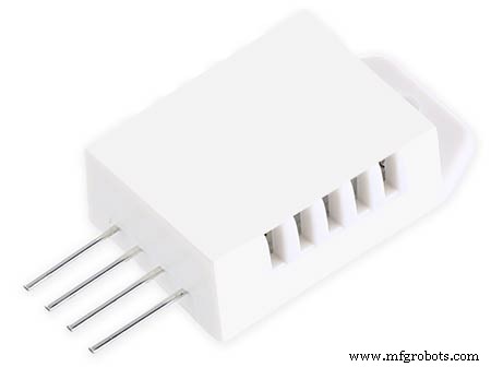
TTP223 Touch Sensor Module
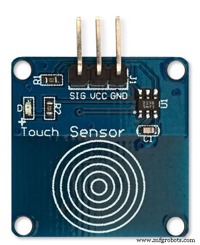
The touch Sensor Module is bolted to the front panel using the glass mounting bolts. The bolt goes through a 5mm hole drilled in the middle of the sensor.Note the mounting bolt is touched to trigger the sensor but is insulated from the sensor itself through plastic washers. Four of these modules are used in the clock one mounted on each corner of the glass.
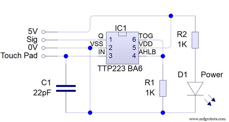
Note the LEDs are not required and are removed from the modules (just break them off) to save power.
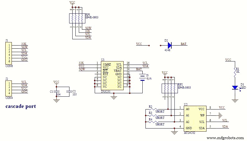
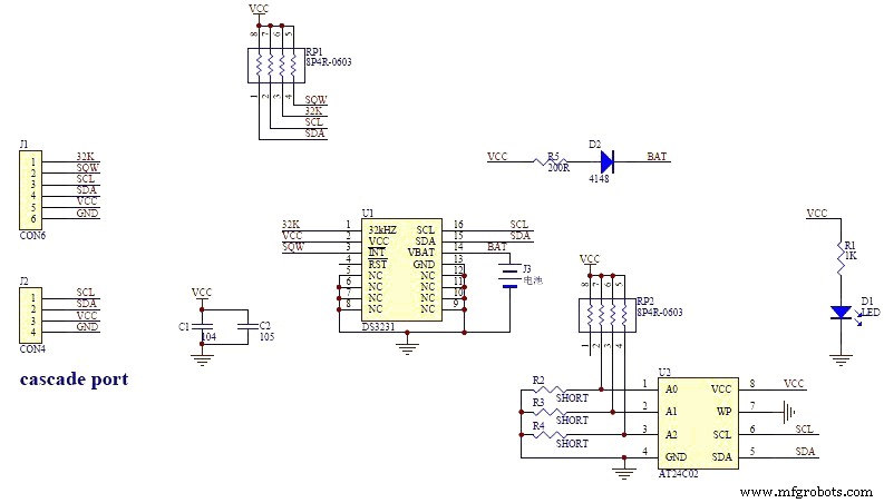
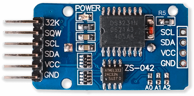
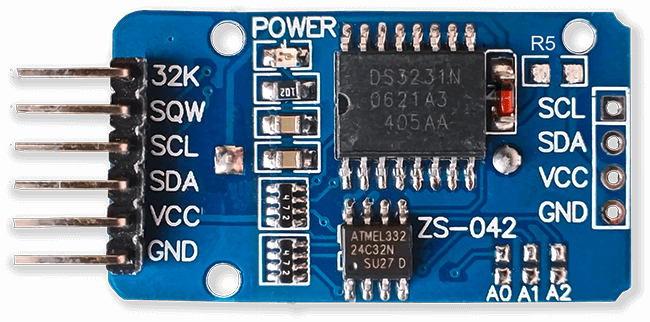
DS3231 AT24C32 I2C Precision Real Time Clock Module
My clock uses a DS3231 AT24C32 I2C Precision Real Time Clock Module.The module comes supplied with a Lithium-Ion rechargeable battery see diagram below. I use a non rechargeable battery so have removed resistor R5 from the module.
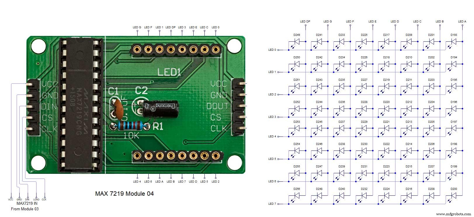
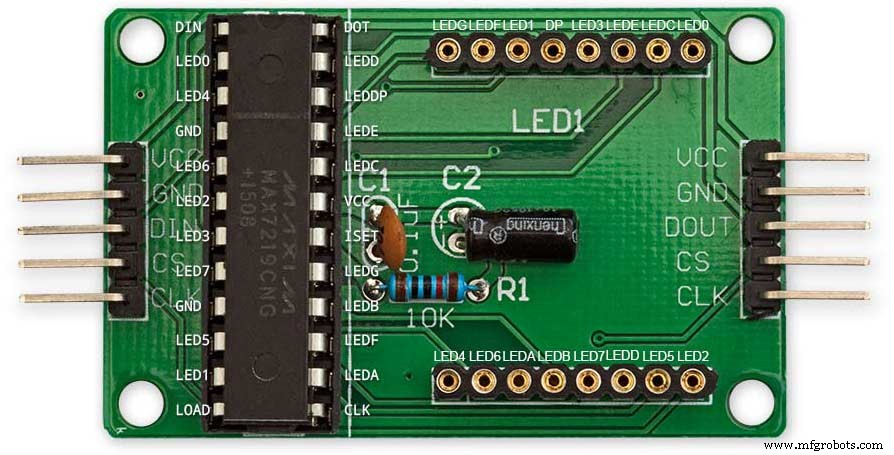
MAX7219 Display Module
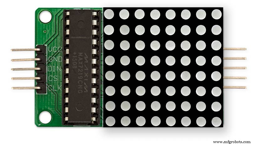
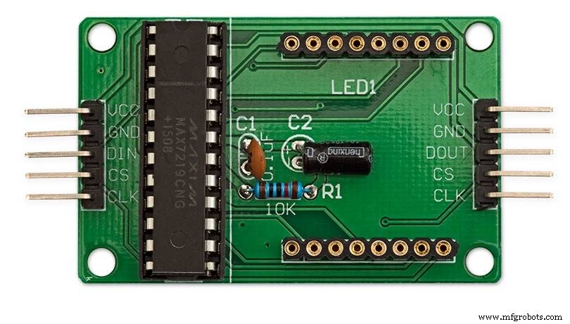
MAX7219 LED current limiting
The max current through the LEDs is set by a single resistor R1 on the module. The value of resistor can be found from the table below.
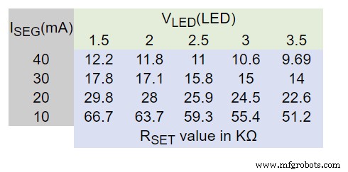
The module comes with a 10K resistor preinstalled but this can be removed and a resister to match your LEDs current added in its place. My LEDs Forward Voltage is 3.2v - 3.8v @ 20mA. They can handle 30mA max but for long LED life 20mA is best. I have used 22KΩ resistors which will limit the current to around 20mA when the light levels are at their peek.
See setting automatic brightness levels.
1088AS LED Dot Matrix display

1088AS LED Dot Matrix display view of lower edge Pins 1 to 8 left to right.
This is used for prototyping and is not required in the final project.
LDR
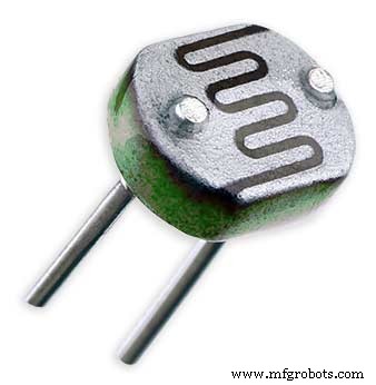
An LDR is used to sense the ambient light levels. The LDR is around 500Ω in bright light and 10MΩ in the dark.
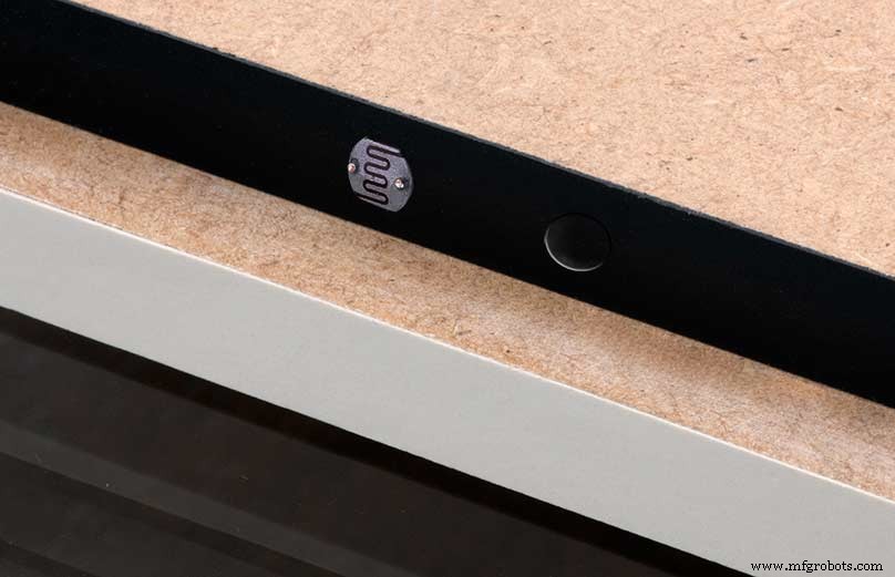
The LDR is positioned underneath the clock on the rear MDF panel.
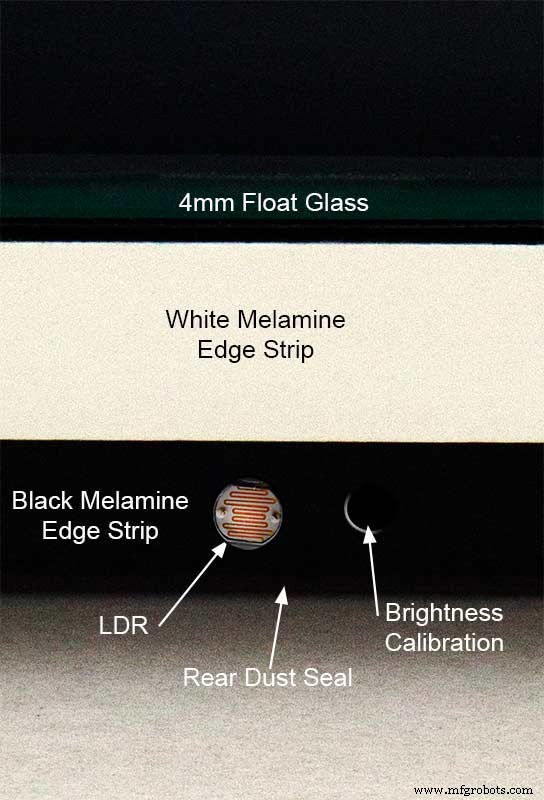
Next to the LDR is a hole to give access to the trimmer resister to calibrate the LED brightness control.
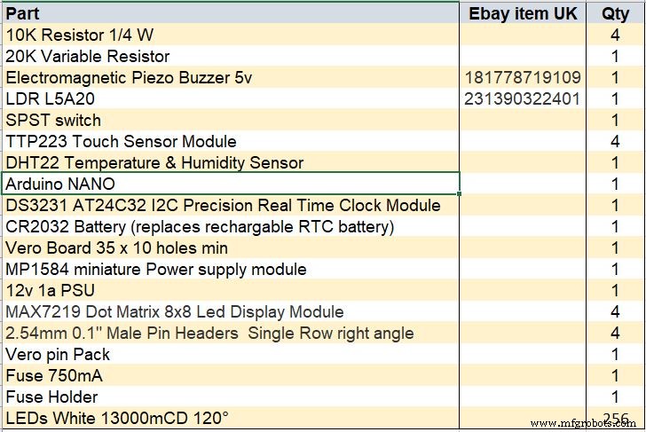
Component List
Step 18 Dust Seals
To prevent ingress of dust two dust seals are fitted.
On the rear MDF board a 2mm soft foam rubber dust seal is fitted. When the clock is hung on its hanging hooks the seal is under pressureand seals the back of the clock to the wall.
The seal is self adhesive and is fitted with a 5mm gap to the edge of the rear MDF board.
On top of the front board to prevent dust getting under the glass a strip of self amalgamating rubber is fitted 5mm from the board edge.
To prevent the glass from cracking when the Chicago bolts are tightened 4 small square of rubber are also fitted around the holes in the glass.
I punched holes for the Chicago Bolts in the rubber with a leather punch.
Step 19:Schematic
Nano Connections
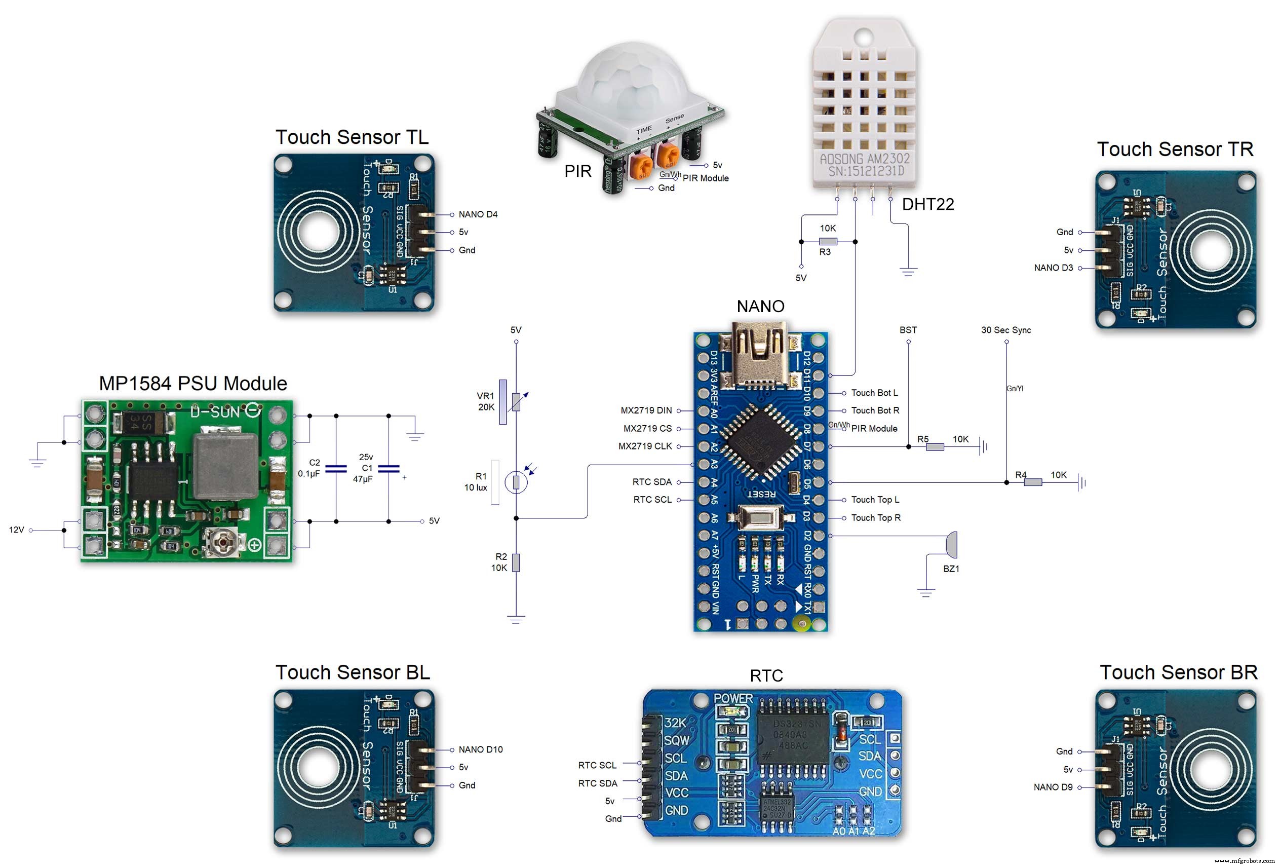
The connections to the Arduino Nano. Download the full size file from the hardware section
MAX2719 connections


The 4 MAX7219 modules and the connected LED matrixes.
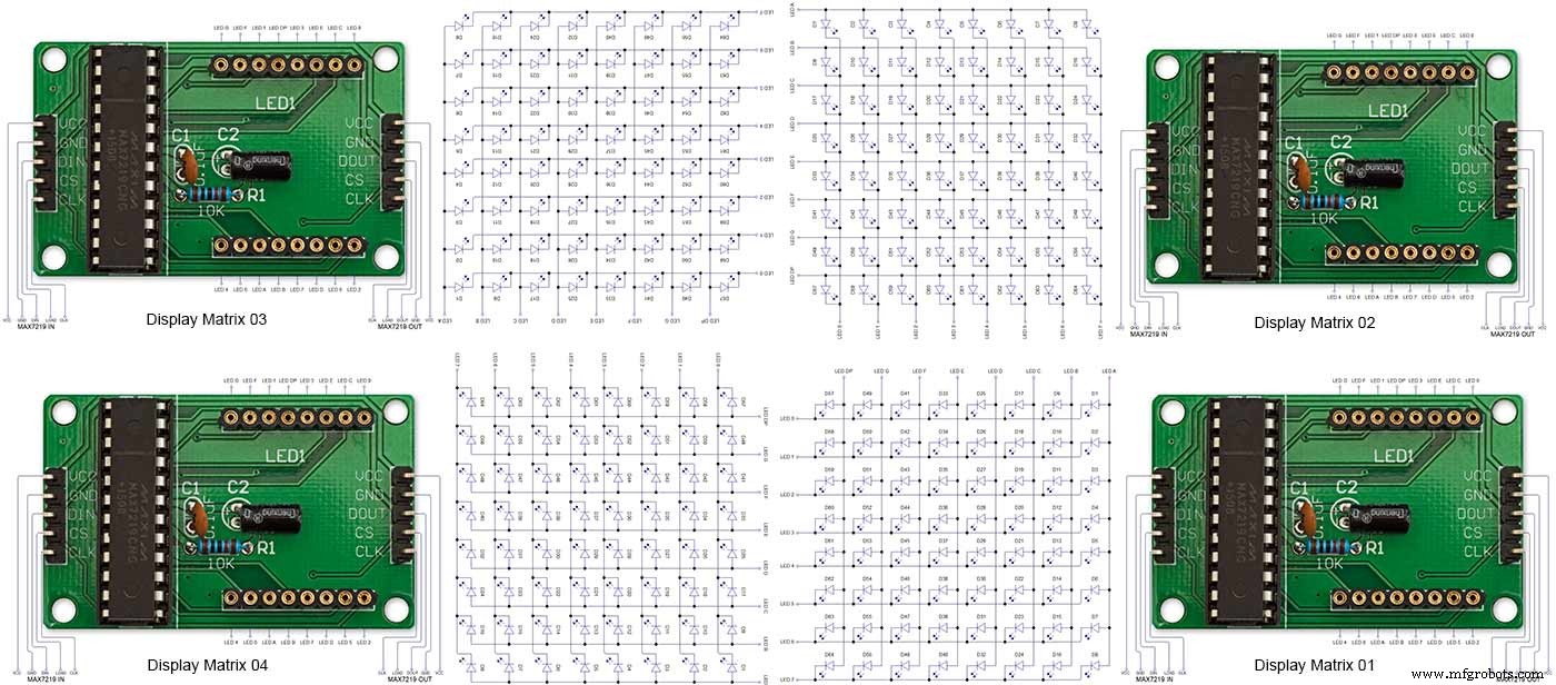
Note the LED display matrixes are rotated anti-clockwise 90 degrees from each other starting from display matrix 01.Display Matrix 01 input is wired to the Arduino CLK, DIN and LOAD the output is taken to the input of Display matrix 02 etc etc.
Step 20:Wiring Building the LED Matrixes
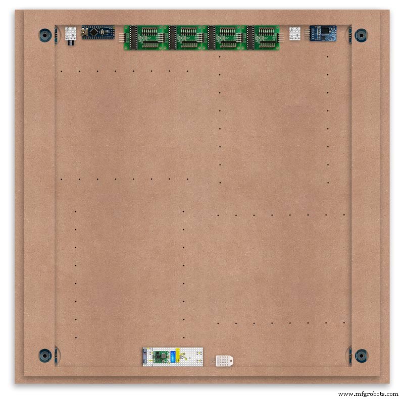
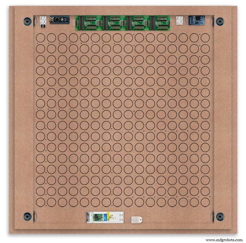
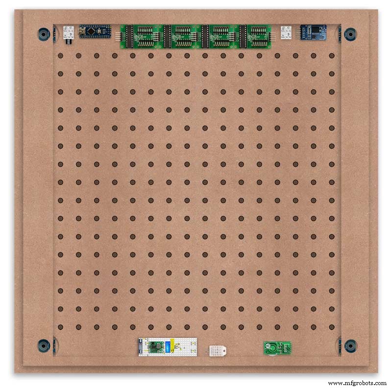
Module Locations

The module locations are shown above. The four sensors are located in the recesses on the main board behind the rear board. Holes are cut into the rear board to allow access for fit the Chicago Bolts/Sensor pads.
The four MAX7219 Display Modules are soldered together and are mounted in the centre top of the board. This keeps the data links between the boards as short as possible.
The Arduino Nano is mounted on the left of the MAX7219 Display Modules and the RTC on the right. The RTC battery holder on the base of the RTC module is recessed into the main board.
The Vero board containing the power module is located on the lower part of the board. There are two power distribution boards mounted on the top of the clock. The main 5v 2A feed cable is taken to both of these boards and power is then distributed to the other boards from these points.
The MAX7219 board power is fed from the left board and daisy chained through each board then taken out the forth board to ensure they are fed with 0v and 5v from both ends.
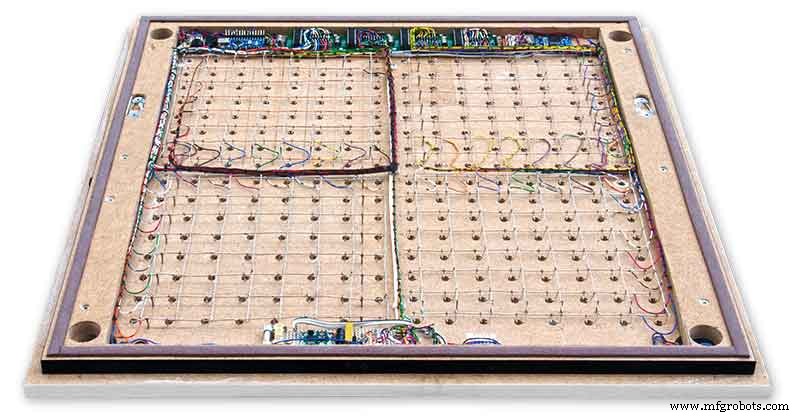
The LED locations are shown. The LED matrixes each contain 64 LEDs and are labelled 1 to 4.
These correspond to the 4 MAX 7219 modules mounted above numbered 1 to 4 left to right. Note this is the rear of the clock so number will be revearsed.
The LED Matrixes are built up off 2 types of BUS Bars per module. A Cathode Bus at 10mm high and an Anode BUS bar at 2mm high.
There are 8 Cathode and 8 Anode BUS Bars per module. Each module has 16 x 15mm panel pins hammered into the board in the position shown to support the 10mm high Cathode BUS.
The 15mm panel pins are hammered in 5mm (I used a 10mm piece of metal bar as a gauge) leaving 10mm as Cathode BUS bar support pins.
As shown above the pins correspond with the thick parts of the board not the recess for the LEDs on the front of the board. Note the LED recess is on the front of the board and can't be seen from the back.

0.9mm copper wire is then soldered to each pair of pins to form the Cathode BUS Bar.
Note the rotation of each module and also the modules are in reverse as it is the back of the board the LEDs are connected to.
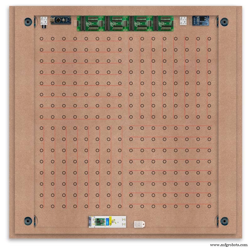
The Anode BUS Bars are shown below in Red and are supported off each LED Anode about 2mm off the MDF board. No Pins required.

Both Cathode &Anode BUS Bar locations are shown below.
Each LED is connected to an Anode and Cathode of the Matrix.
Step 21:Wiring the LEDs
LEDs
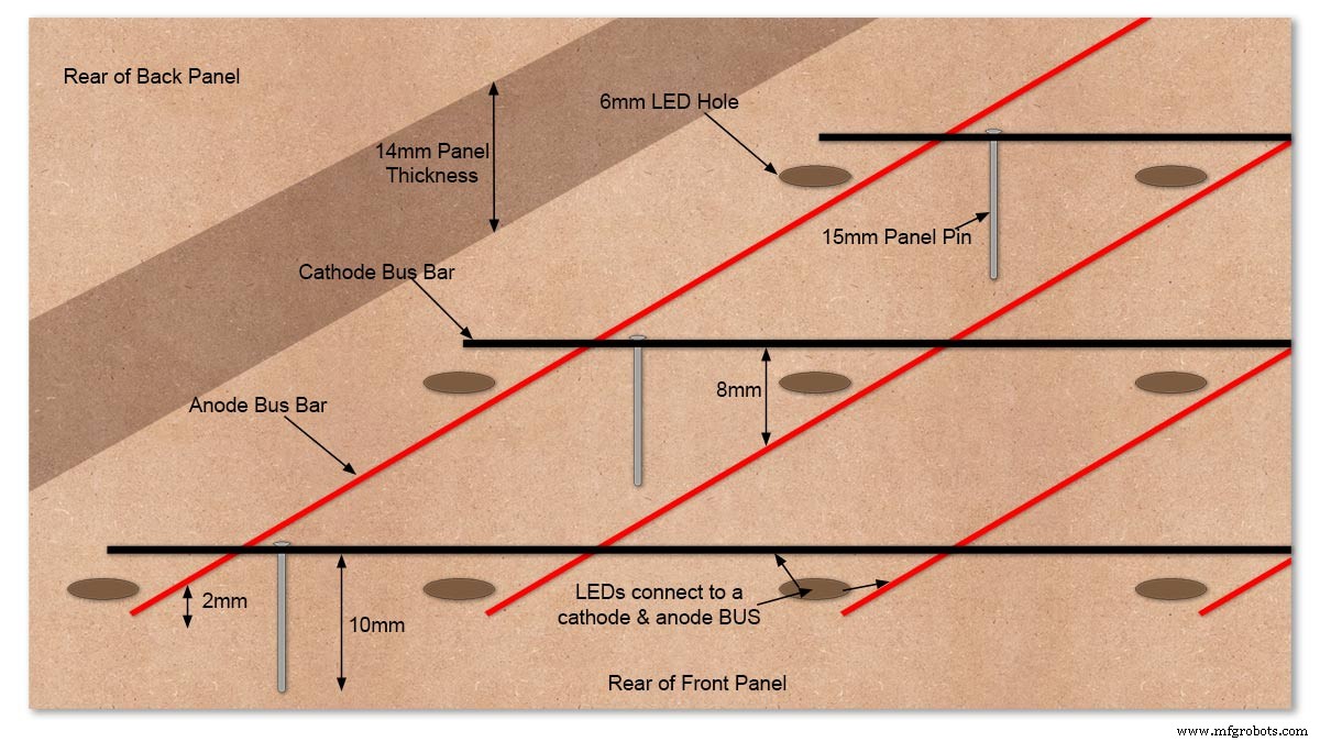
Diagram showing Bus Bar layout with panel pins supporting the Cathode Bus. This module has horizontal Cathode and vertical Anode Bus Bars.
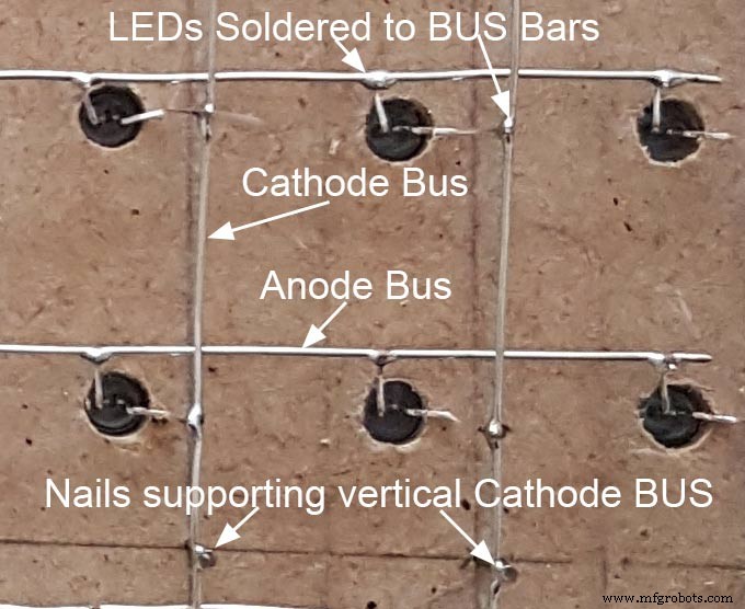
Close up section of Module wiring.The Cathode BUS Bars run vertically and the Anode BUS Bars run horizontally on this module. The Anode &Cathode BUS Bars have an 8mm vertical separation.
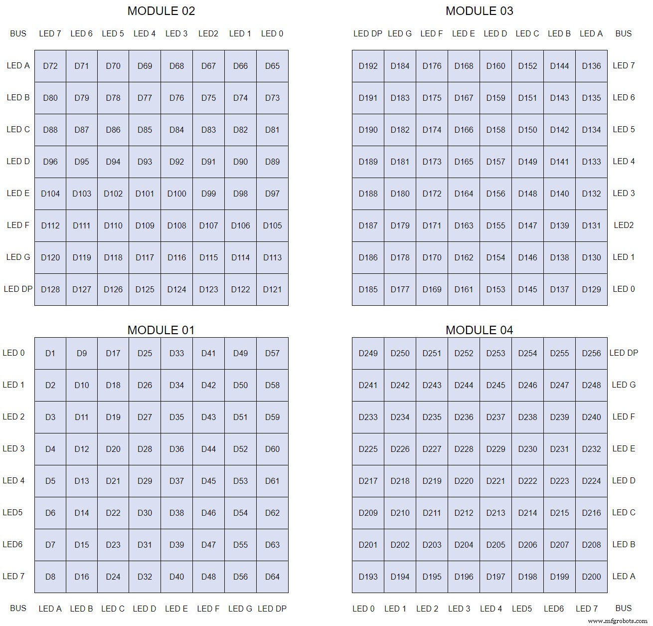
The LEDs are connected to the matrixes and MAX7219 modules from the rear. The LED positions will be reversed and of course rotated 90° relative to the next module. This makes it very complicated connecting the correct LEDs and Bus bars from the rear of the board. The table below shows the LED positions in the blue boxes with the BUS Bar matrix position in black around the outside as they appear from the back of the front MDF board.
The LEDs are bent in a jig to keep the position in the display constant and to speed up construction. Each LED has four bends two on each leg that's 1024 in total! The Cathode leg is bent 90° from the Anode.
The Matrix grids are wired to the corresponding pins on the MAX7219 modules according to the layout table.
There are 16 wires to each module.
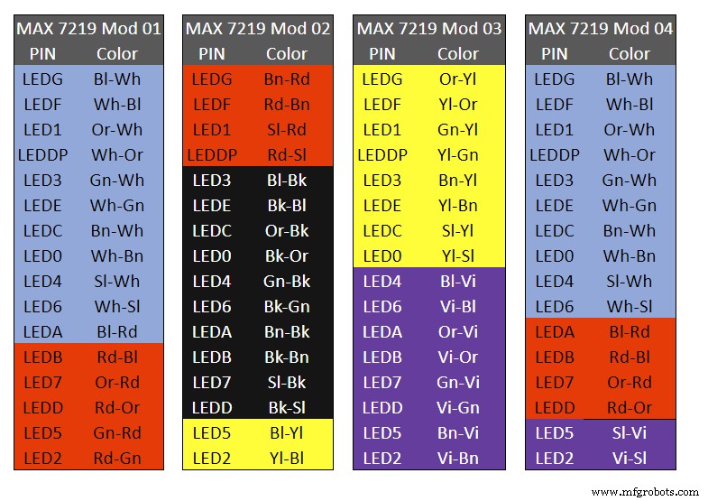
Table 1 Module LED Matrix Wiring Colour Code is shown above.
Each Module has 16 wires connecting it to the LED Matrixes. I have used 50pr 0.5mm cable so the last 14pr colours are duplicated. On Mod 4 I went out of order and missed out the Sl/Vi at the start so have put it in at the end.
Step 22:Wiring Modifying the MAX7219 Modules 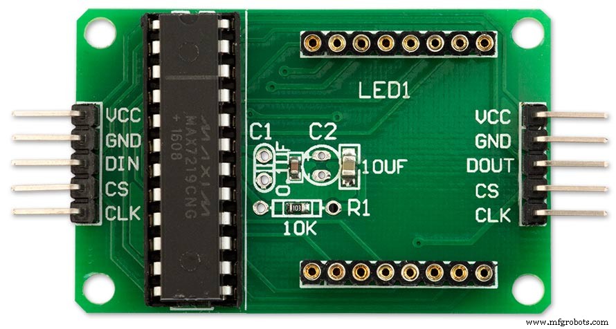
Before wires can be connected to the MAX 2917 modules they will need to be modified.
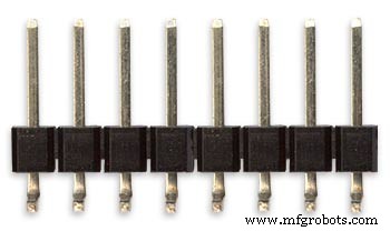
Two sets of 8 90° pin connectors will to be soldered to the lower edge of the existing LED matrix connector.

Modified MAX7219 module with 90° pin connectors soldered in place to the bottom of the old LED Matrix connectors.
Wires are taken away from these points to the LED matrix on the main MDF board as per the LED Matrix Wiring Colour Code table on the previous step.
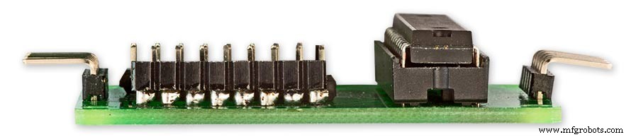
Side view showing the pins soldered to the side of the old LED Matrix connector pins just above the PCB.
Note if your MAX7219 Module does not have surface mount components the 90° pin connectors may need to be trimmed back so they don't foul R1, C1 or C2.
MAX7219 LED current limitingThe max current through the LEDs is set by a single resistor R1 on the module. The value of resistor can be found from the table below.

The module comes with a 10K resistor preinstalled but this can be removed and a resistor to match your LEDs current added in its place.
My LEDs Forward Voltage is 3.2v - 3.8v @ 20mA. They can handle 30mA max but for long LED life 20mA is best. I have used 22KΩ resistors which will limit the current to around 20mA when the light levels are at their peek.
Note this sets the max current through your LEDs actual brightness is controlled by the LDR/software/ trimmer resistor and will usually be far less than this.
Setting Automatic Brightness Levels
The clock automatically senses the ambient light and adjusts the LEDs accordingly.
When first installed the clock will need to be calibrated to the maximum light levels in its actual location.

Connect a mobile, laptop/tablet etc via a suitable cable to the mini USB port of the clock and open an app to monitor the serial port.
I use Slick USB 2 Serial Terminal on my S7 via an OTG cable and USB to mini USB cable.
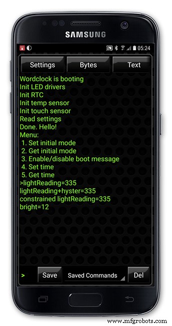
The clock will reboot and after the initial start screen you will see the following data updating down the screen.
You don't need to worry about lightReading or constrained lightReading+hyster just light reading, and bright.
With the clock in position and the ambient light at its maximum levels carefully insert a flat bladed jewellers screwdriver into the access hole just to the right of the light sensor.
Turn the screwdriver slowly until the light reading =600 (or your level set in brightness.cpp) and bright =15.
Your clock will now go to max brightness when the ambient light is at its maximum.
If you turn the screwdriver too far the light reading will go over 600 but the bright reading will not increase.
If you want the clock to be dimmer right across the range of ambient light levels adjust the light reading to a level less than 600 at max ambient light levels.
Note when bright=15 this will output the max current to the LEDs. The max current is set by R1( RSET) on the MAX7219 module and this should be chosen for your type of LED used in the display.
Step 23:Wring Mini USB Port 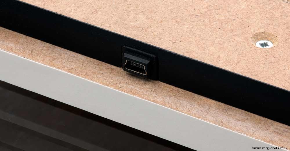
To allow adjustment/checking of light levels and programming of the clock a Mini USB socket is cut into the right hand side of the rear MDF sheet.
I have used a 25cm 90° Right angle Mini USB Male to Female Extension Cable and stripped back the insulation sleeve and shielding to expose the wires. This allows the cable to bend around the sharp angles and tight spaces of the enclosure.
Step 24:PIR Controlled Display Shutdown
This is optional as a Doppler Radar module can be fitted inside the clock instead.
See next section.
The PIR when enabled on the word clock menu (bott left PIR On, bott right PIR Off) turns on the display when movement is detected in the room.
When no movement is detected the display turns off after a set period of time. When the PIR is enabled the displays shows "PIR ON" and when disabled (display always on) it shows "PIR OFF" Note when the PIR is not enabled the display is always On.
The PIR module is fitted remote from the clock in a modified chrome light switch box. The box is cut into a plasterboard wall and also contains a switch to turn the clock off. The module itself is very small and can be mounted in a tiny enclosure if you don't want it on show. It will not work behind glass so if you wanted to mount it on the clock a hole would need to cut in the glass. This is very easy to do with a large hole cutter.
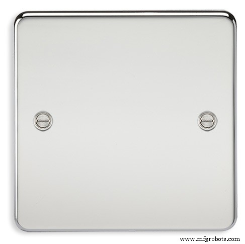
A blank chrome switch plate and back box are used to house the power switch and PIR module.
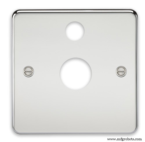
Two holes are drilled in the blank switch plate for the power switch and PIR lens.
The hole are centre punched, pilot drilled and then drilled out just big enough for a step cutter to fit through. The hole for the PIR diffuser is cut just big enough for the lens to go through with a friction fit.
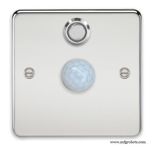
The completed switch plate.
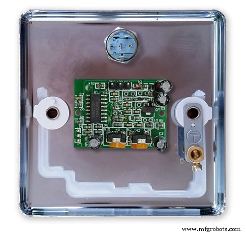
The 12 volt supply +ve is terminated on the switch with the 0v terminated on the earth screw.
12 volts is then fed back upto the clock PSU Vero board from the other side of the switch and again the earth screw. 5 volts are fed from the clock PSU Vero board to supply the PIR module.
The 5 volts and PIR sensor wire to the clock terminate on PCB header sockets. These are is plugged into the PIR Module header pins. The sync cable is terminated on a header pins and connects to the Master Clock 30 second sync cable via a single header socket.
The PIR has 2 trimmer resistors for adjusting sensitivity and also length of time the PIR &display stay activated.
PIR On/Off Control:The PIR is turned on and off in word clock mode by touching the bottom left sensor to turn the PIR on or by touching the right sensor to turn the PIR off. Note when the PIR is set to off the display stays on permanently. When you change the PIR setting the work "PIR ON" or "PIR OFF" is displayed for 5 seconds.
When initial power up the default is PIR off if you switch the PIR On straight away the display will go off as the PIR takes a minute or so to initialise before detecting movement.
Photo 6 &7 "PIR ON" or "PIR OFF" are displayed for 5 seconds when PIR setting is changed.
Step 25:Doppler Radar Control Option
Optional Doppler Radar Module can be added in place of the PIR above.
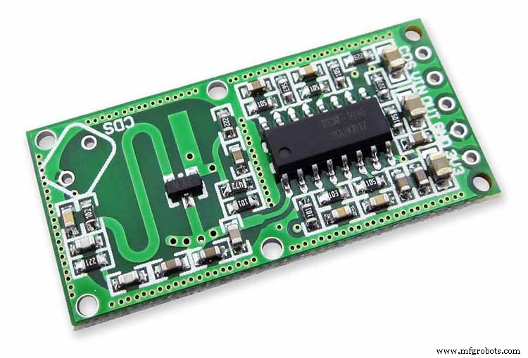
The Doppler Radar when enabled on the Word Clock menu (bott left PIR On, bott right PIR Off) turns on the display when movement is detected in the room. A check is made for motion on every quarter hour. When no movement is detected the display turns off until movement is detected again.
When the PIR is enabled the displays shows "PIR ON" and when disabled (display always on) it shows "PIR OFF" Note when the PIR is not enabled the display is always On. Unlike PIR modules the Doppler Radar module can see through glass and plastic and is fixed into the case of the clock behind the glass and PVC sticker. The module has a range of around 5m or 16' 5".
Doppler Radar Module fixed inside the case. A hole is drilled in the front panel to allow the module to monitor the room.
Front panel showing hole through to the Doppler Radar module microwave sensor.
The module is hidden from view behind the PVC sticker and glass.
Step 26:PIR/Doppler Radar On Off Control
The PIR is turned on &off in word clock mode by touching the bottom left sensor to turn the PIR on or by touching the right sensor to turn the PIR off.
Note when the PIR is set to off the display stays on permanently.
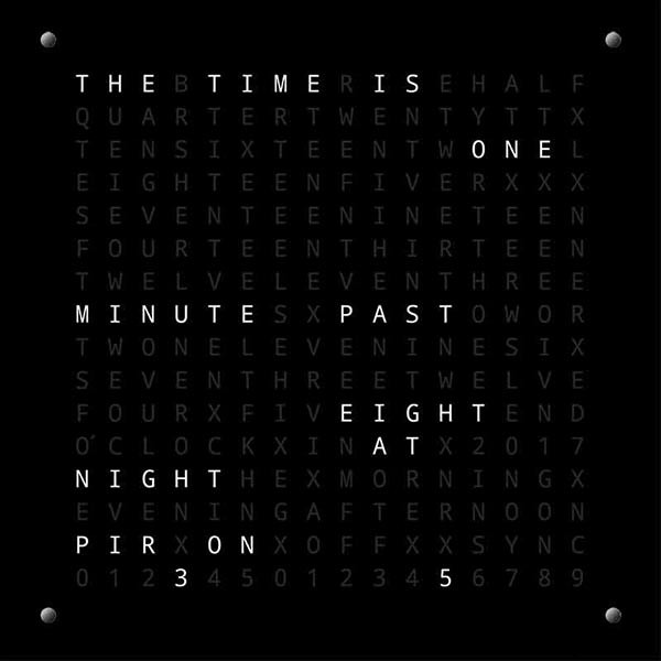

When you change the PIR setting the work "PIR ON" or "PIR OFF" is displayed for 5 seconds.
When initial power up the default is PIR off if you switch the PIR On straight away the display will go off as the PIR takes a minute or so to initialise before detecting movement.
Step 27:Setting Automatic Brightness Levels
The clock automatically senses the ambient light and adjusts the LEDs accordingly.
When first installed the clock will need to be calibrated to the maximum light levels in its actual location. Connect a mobile, laptop/tablet etc via a suitable cable to the mini USB port of the clock and open an app to monitor the serial port. I use Slick USB 2 Serial Terminal on my S7 via an OTG cable and USB to mini USB cable.

The clock will reboot and after the initial start screen you will see the following data updating down the screen.
You don't need to worry about lightReading or constrained lightReading+hyster just light reading, and bright.With the clock in position and the ambient light at its maximum levels carefully insert a flat bladed jewellers screwdriver into the access hole just to the right of the light sensor. Turn the screwdriver slowly until the light reading =600 (or your level set in brightness.cpp) and bright =15. Your clock will now go to max brightness when the ambient light is at its maximum. If you turn the screwdriver too far the light reading will go over 600 but the bright reading will not increase.
If you want the clock to be dimmer right across the range of ambient light levels adjust the light reading to a level less than 600 at max ambient light levels.
Note when bright=15 this will output the max current to the LEDs. The max current is set by R1( RSET) on the MAX7219 module and this should be chosen for your type of LED used in the display.
Step 28:Setting the Clock
The clock is set in the digital clock mode by touching the bottom left sensor.
The hour digits will now flash twice a second to indicate the clock is in time setting mode.In this mode the sensors have the following functions.
Top right - steps the hours or mins digits up
Top left- steps the hours or mins digits down
Bottom left 1sr press - enters the time setting mode selecting hours digits
Bottom left 2nd press -selects the mins digits for changing
Bottom left 3rd press -exits time setting mode and sets the time
Bottom right - resets the seconds to 00
Step 29:Synchronisation
If you have connected a 30 second master clock sync cable then the clock will jump back or forward to 30 seconds when out of time setting mode. If you don't have a Master Clock to sync to then the clock will fall back on the on board temperature compensated real time clock which in itself is a very precise quartz clock.
Just reset the seconds roughly in sync to the seconds (within 10 seconds either way) and wait for the clock to sync once out of time setting mode.
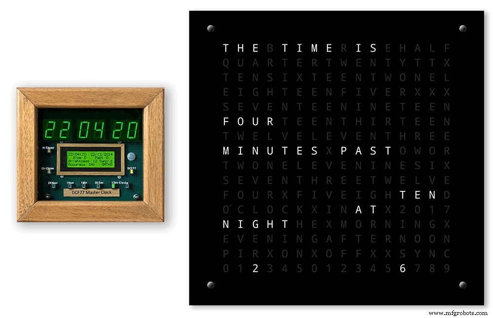
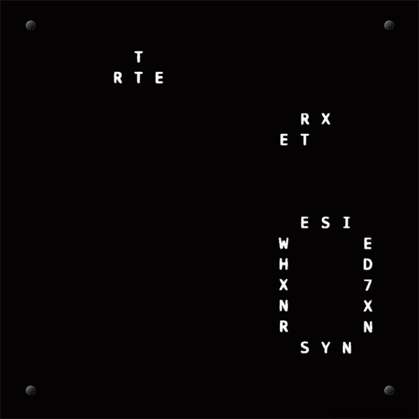
The animated loop below shows the Word Clock is running fast by several seconds. A synchronisation pulse is received from the Master Clock every 30 seconds on the minute and half minute synchronising the clock on 30 seconds.
The clock will ignore the 30 second synchronisation pulse from the Master Clock at 0 seconds. Note clock synchronisation only happens when the Word Clock is 20 seconds past and 20 seconds to a minute. In normal operation the sync pulse corrects the clock to within a fraction of a second so you will see the word "SYNC" appear with no visible correction to the seconds.
Note the synchronisation pulse is received every 30 seconds but the clock will ignore pulses at 0 seconds.
Step 30:Software &Making Changes
The software can be downloaded from the software tab and contains the following modules.
Program Files Modules
Brett_wordclock_v4_3.ino Main program, latest update includes shortened code saving 10% in size.
Thanks to srdevil for providing the updated code for this seconds display.
brightness.cpp/.h Brightness autoadjustment
character.cpp/.h Character (digit) definitions
credits.cpp/.h Ending Credits
display.cpp/.h Display &LED functions
life.cpp/.h Game of Life
serial.cpp/.h Serial port setup menu
simon.cpp/.h Simon Says game
temphum.cpp/.h Temperature &Humidity displa
tetris.cpp/.h Tetris game
time.cpp/.h Wordclock, digital clock
timeanalog.cpp/.h Analogue clock
touchbuttons.cpp/.h Touch buttons, mode switching
Third party libraries:
Chronodot.cpp/.h Chronodot library (for DS3231)
DHT.cpp/.h Temperature sensor library (for DHT22)
LedControl.cpp/.h LedControl library (for MAX7219)
stc.cpp/.h/platform.h Simple Tetris Clone library
pitches.h Note frequencies from the Arduino webpage
When you want to make changes to my code you can compare my code to the "Catalan Code" to make it easier to understand what changes you need to make. I have added //Brett to my code to highlight my changes.
Changing the code.
If like me you are not very good at coding just play around with the code to get an understanding of how it works.
I just save a different version each time I make even a tiny change. This way if I mess up I can go back a version and start again.
If you are keeping my linear seconds display update the version number on the display so you know what version you are trying out each time. This is done in the module credit.h around line 47.
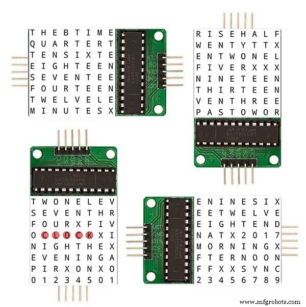
It would take far too long to explain all the code but here is a very brief guide on how to change the words and when they are displayed.
The WORDS are set in time.h
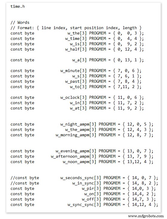
On line 52 we have
const byte w_the[3] PROGMEM ={ 0, 0, 3 };
The word "THE" is described in this line with the LED location in the curly brackets "{ 0, 0, 3 }"
This is the co-ordinate of the LEDs we are gong to light when we call "w_the"
The LED matrix numbers starts top left and start from 0 so "{ 0, 0, 3 }" is the first LED across and down the 3 just means the 3 LEDs across including this one will light. As the letters THE are in this position the word "THE" is displayed.
Similarly the word "TIME" would be lit by lighting the four LEDs here { 0, 4, 4 } or row 0, 5th LED along and light 4 LEDs (remember to count from 0).
Working you way down the page shows the position of all the words.
Controlling when words are lit
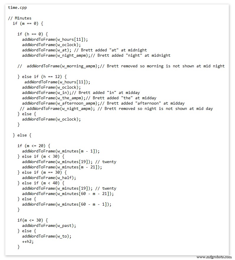
This happens in the module time.cpp
Here you just make a list of rules to tell the clock what words to light at certain times.
Pic above shows part of the code starting with line 695
At midnight we want to make the clock say "THE TIME IS TWELVE OCLOCK AT NIGHT"
Midnight is 00 00
"THE TIME IS" is always displayed from lines 687
So we add the rules if minutes are 0, then if hours are 0 show the word for hours "TWELVE" and the word "OCLOCK" the word "AT" and the word "NIGHT"
If you follow the code down all the possible time combinations are covered.
Analogue Clock Code Change - increase in time definition One of the comments sent to me by srdevil was some code changes. His comment can be seen below.
I have not had time to test the code but have included it below if you want to try it out.
" If the time is 18:00, it points up (long leg) and down (short leg). But when the time is 18:59, it still points totally down (short leg) so it looks like the time is 17:59 on a normal clock. My brother change the code so that if it is>HH:15 the small pointer moves already to the next number. As of this we also increased the resolution in the part between>HH:15 -
Code on the comments section or can be seen here http://home.btconnect.com/brettoliver1/Word_Clock/Word_Clock.htm#analogeclock
Kode
Brett_wordclock_v4_5.zipArduino
Load into Aduino IDENo preview (download only).
Github
https://github.com/wouterdevinck/wordclockhttps://github.com/wouterdevinck/wordclock Github
https://github.com/svcabre/wordclockhttps://github.com/svcabre/wordclock My Word Clock on GITHUB
Schematics and code https://github.com/brettoliver/wordclock Suku cadang dan penutup khusus
Vinyl Sticker Design in Inkscape (free to download) change as required brett11_print_ready_6bbpMTDyFa.svg Skema
Schemaic showing main board connections 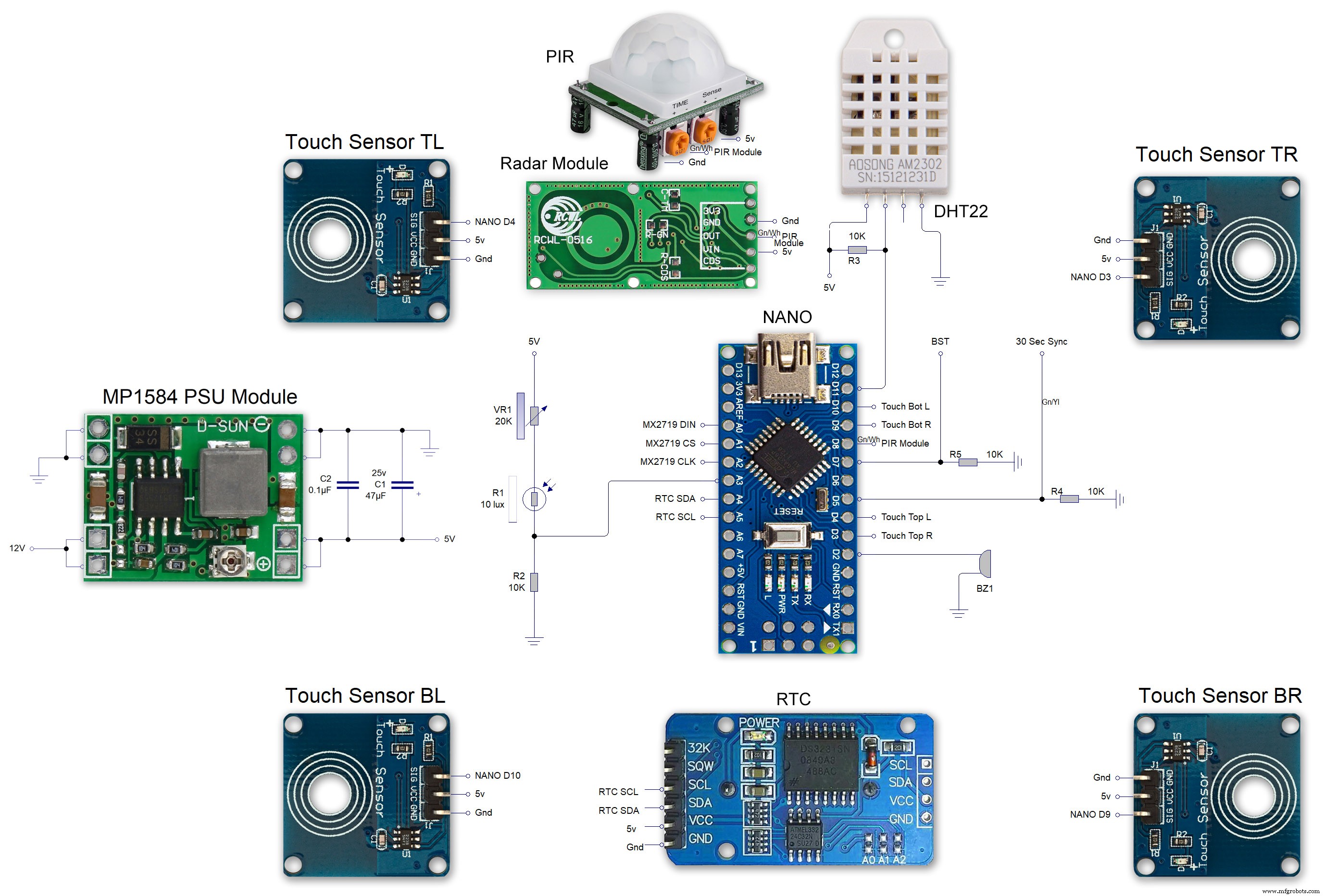 MAX7219 7 segment display module 01 LED connections
 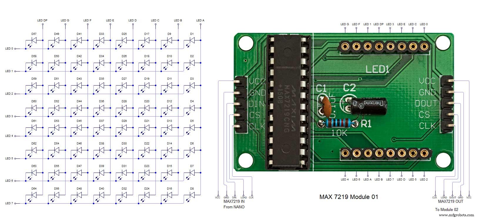 MAX7219 7 segment display module 02 LED connections
 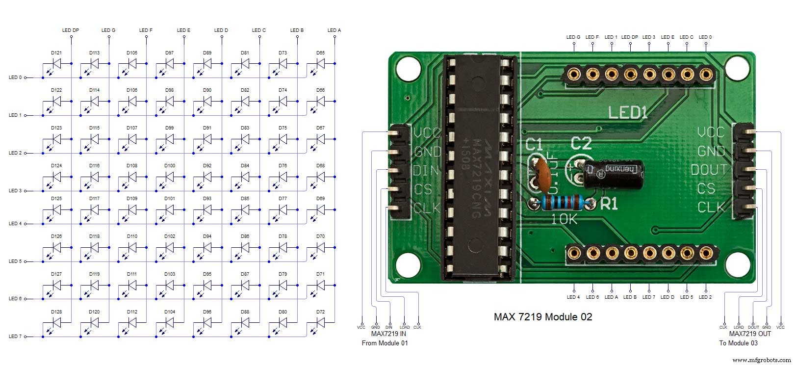 MAX7219 7 segment display module 03 LED connections
 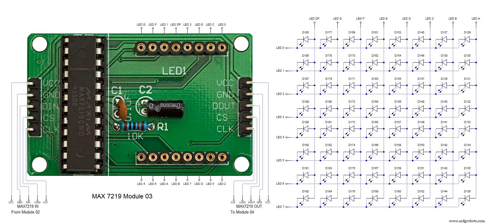 MAX7219 7 segment display module 04 LED connections