

Proses manufaktur

Manufaktur industri
 |
| × | 1 | |||
 |
| × | 1 | |||
 |
| × | 4 | |||
 |
| × | 1 | |||
 |
| × | 2 | |||
 |
| × | 3 | |||
 |
| × | 4 | |||
 |
| × | 2 | |||
 |
| × | 1 | |||
 |
| × | 1 |
 |
| |||
 |
|
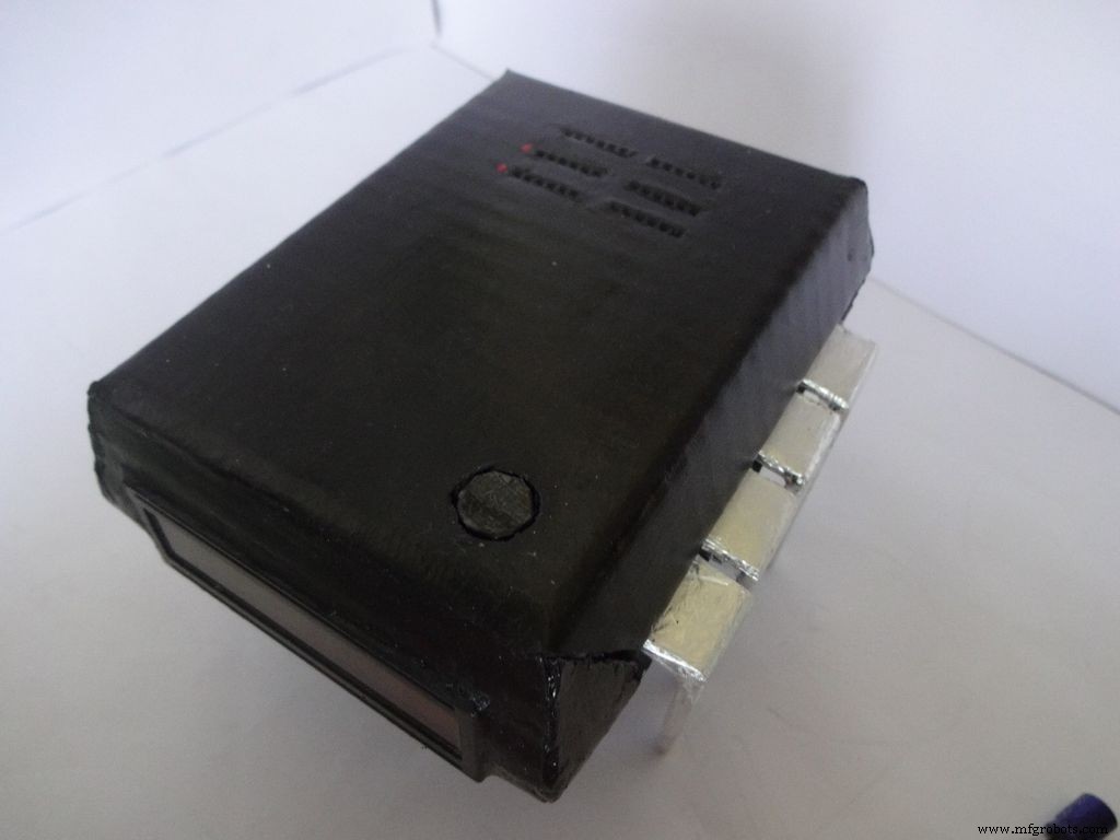

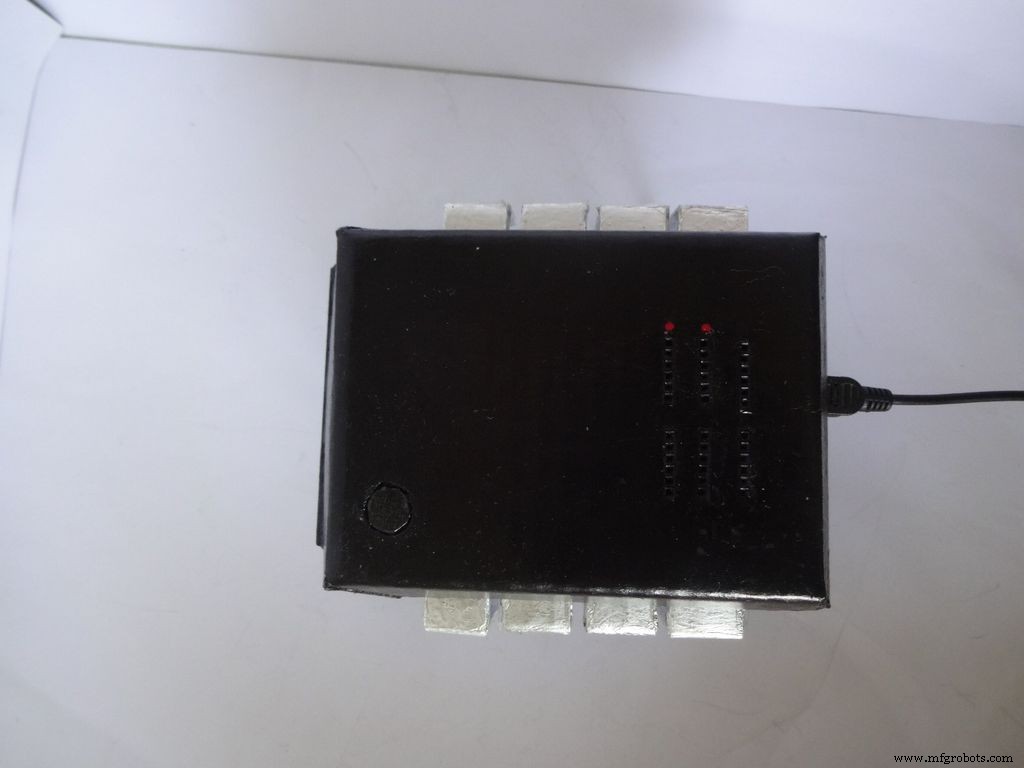
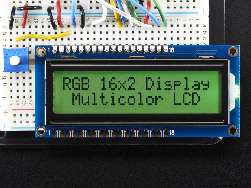
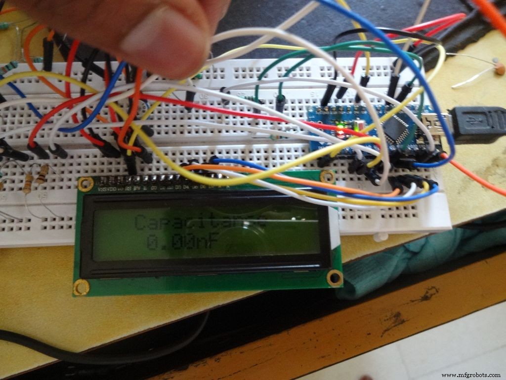
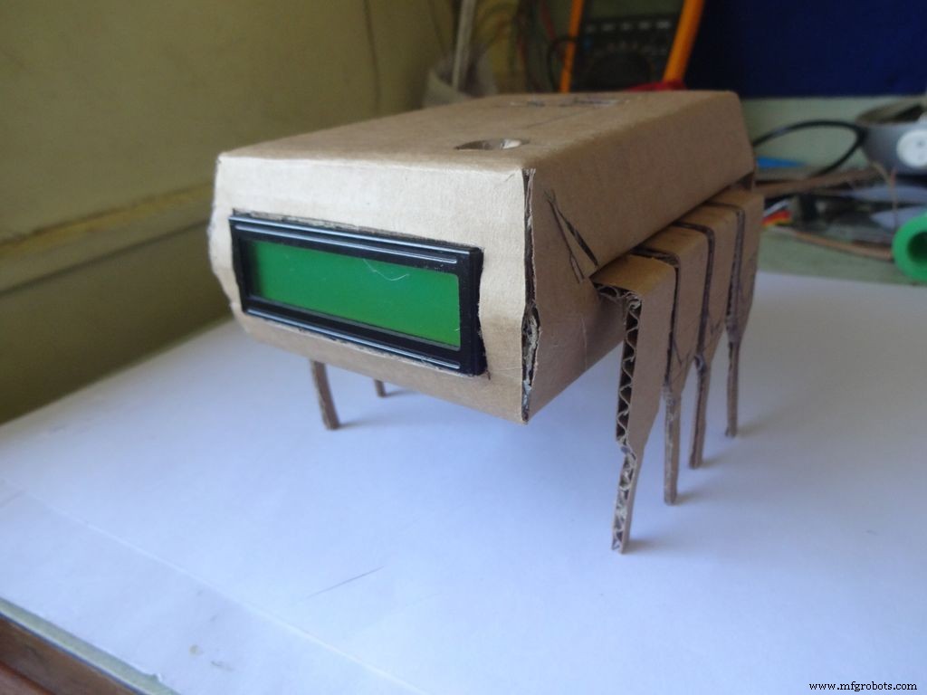
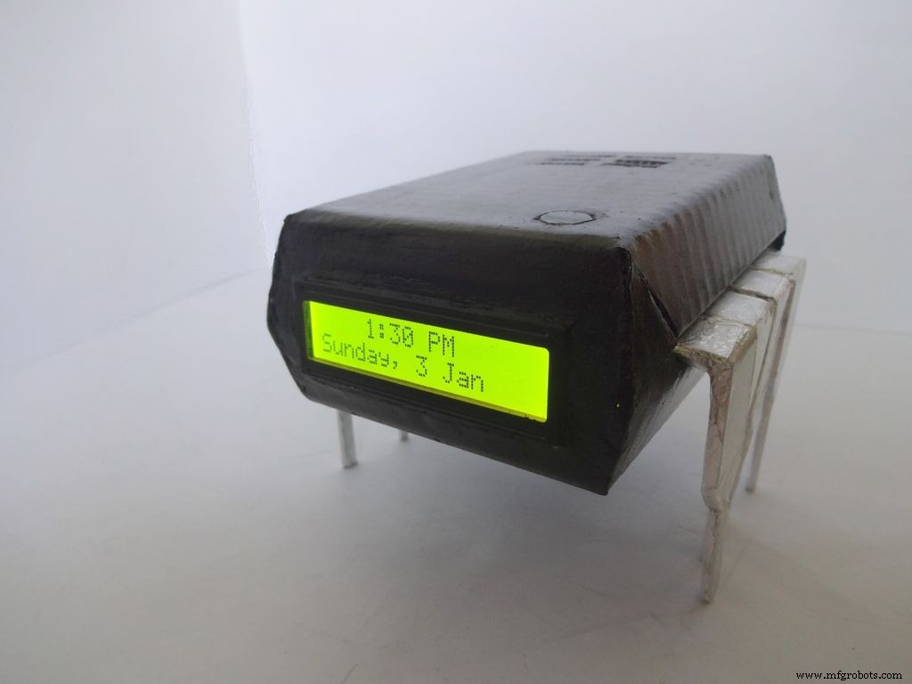
IC Pendamping adalah Jam + Ohmmeter + Pengukur Kapasitansi + Penguji Dioda yang terlihat sangat keren! Nyalakan dengan menekan Pin 1 IC! Simpan ini di meja kerja Anda untuk pengujian cepat komponen dan waktu pemeriksaan. Dapat dijalankan dengan baterai atau dengan USB jika Anda memiliki persediaan di dekat meja kerja Anda.
Saya selalu ingin menerbitkan sebuah proyek tetapi tidak pernah menemukan sesuatu yang unik untuk dibuat sampai sekarang! Idenya muncul ketika saya ingin menguji beberapa kapasitor untuk melihat apakah mereka rusak atau tidak. Saya hanya memiliki multimeter yang tersedia dan tidak memiliki fungsi pengukuran kapasitansi. Setelah mencari tentang itu, saya mengetahui bahwa Arduino dapat melakukan ini. Saya memutuskan bahwa saya akan membuatnya tetapi melihat pin yang tidak digunakan pada Arduino tidak terlalu memuaskan, jadi saya memutuskan untuk menambahkan Ohmmeter mulai otomatis, penguji LED/Dioda cepat, dan Jam RTC juga! Saya juga ingin mengukur nilai secara langsung dengan mencolokkan komponen dan tidak menggunakan probe apa pun. Desainnya harus unik sehingga setelah melakukan brainstorming desain IC dibuat!
Edit (07/01/2016) :Tes kontinuitas opsional telah ditambahkan, silakan lihat bagian komentar.
Artikel ini menjelaskan dengan sangat rinci bagaimana saya membuat ini dan bagaimana Anda juga dapat membuatnya sendiri. Ini ramah pemula dan siapa saja dengan 2-3 minggu pengalaman Arduino /Elektronik dapat membangun ini!
Desainnya dapat dimodifikasi dan Anda dapat menghapus/menambahkan fitur baru sesuai kebutuhan Anda. Saya membuat kasing dengan karton tetapi jika Anda memiliki keterampilan, Anda dapat melakukannya dengan kayu atau cetak 3D.
Saya telah mencoba untuk mengambil dan melampirkan gambar di setiap langkah yang saya lakukan (Banyak di setiap langkah!). Sebagian besar diambil beberapa kali hingga saya mendapatkan sudut/cahaya terbaik, tetapi masih ada beberapa yang agak buram karena memegang semuanya dengan dua tangan terkadang sulit.
Saya telah memecahkan seluruh kode dan kabel menjadi beberapa bagian, persis bagaimana saya membuatnya. Kode yang disertakan banyak dikomentari dan diindentasi dengan benar. Saat kita melanjutkan. kami akan menggabungkan semua kode dan pengkabelan langkah demi langkah untuk membuat IC akhir. Ini akan membantu siapa pun memahaminya dengan jelas. Jika tidak, beri tahu saya di komentar.
Bahkan jika Anda memutuskan untuk tidak membuatnya, cobalah di papan tempat memotong roti atau setidaknya baca ini sekali karena pasti ada beberapa metode atau trik atau sesuatu yang dapat Anda pelajari di sini dan akan berguna bagi Anda suatu hari nanti (Serius, Anda tidak pernah tahu kapan itu klik!)
Langkah 1:Alat dan Komponen yang dibutuhkan
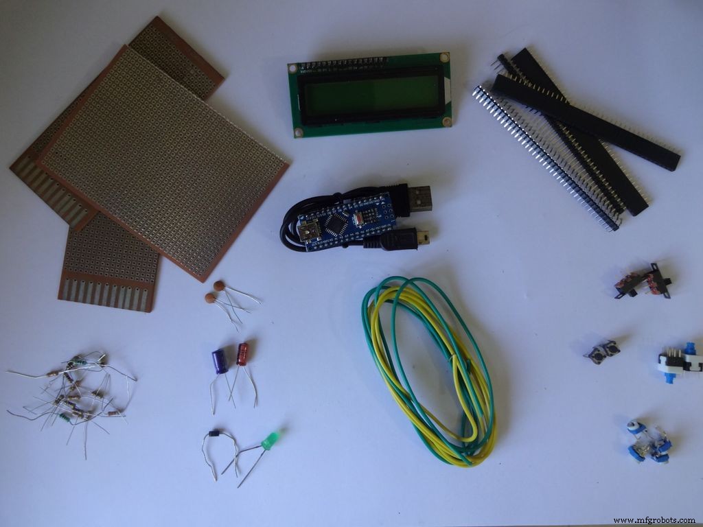

Daftar Komponen dan Bahan yang Digunakan (Tautan toko hanya untuk referensi):
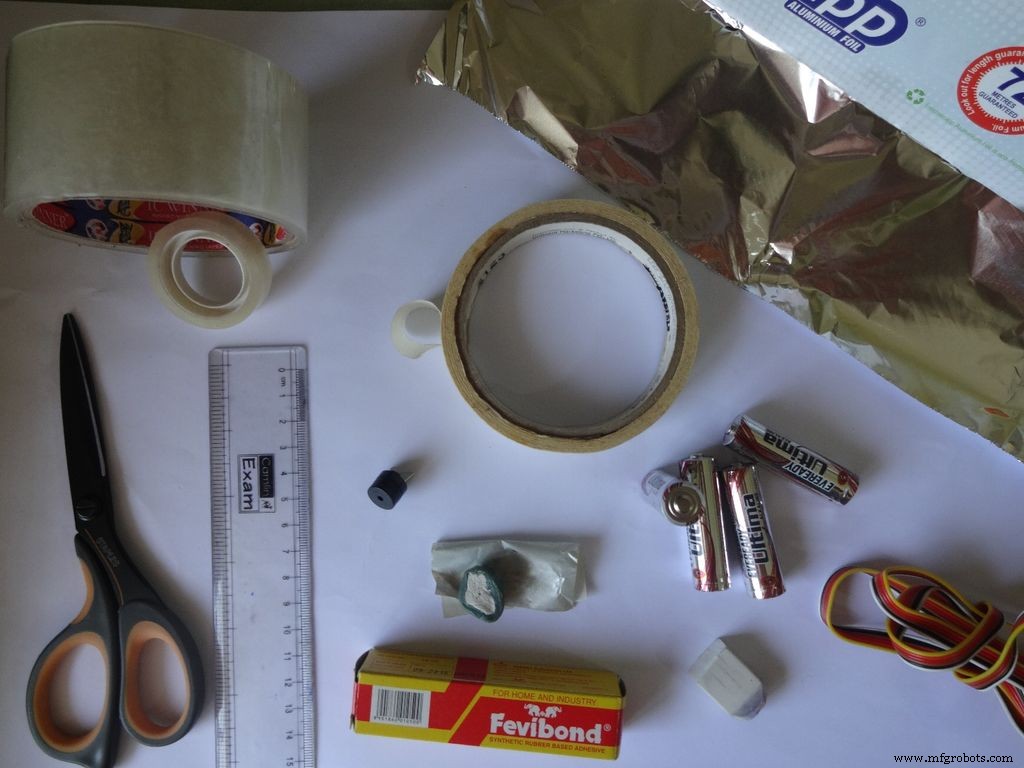
Alat yang dibutuhkan:
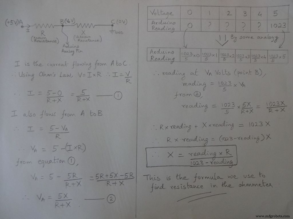
Langkah 2:Ohmmeter - Konsep
Ide dasar untuk mengukur resistansi berasal dari pembagi tegangan.
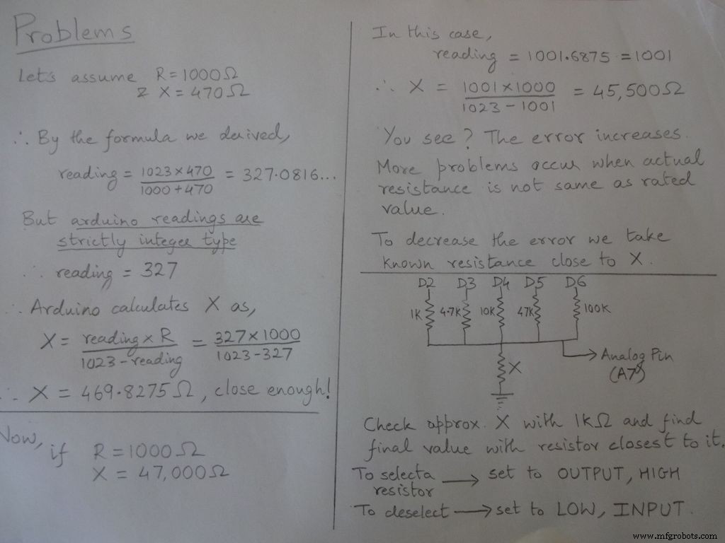
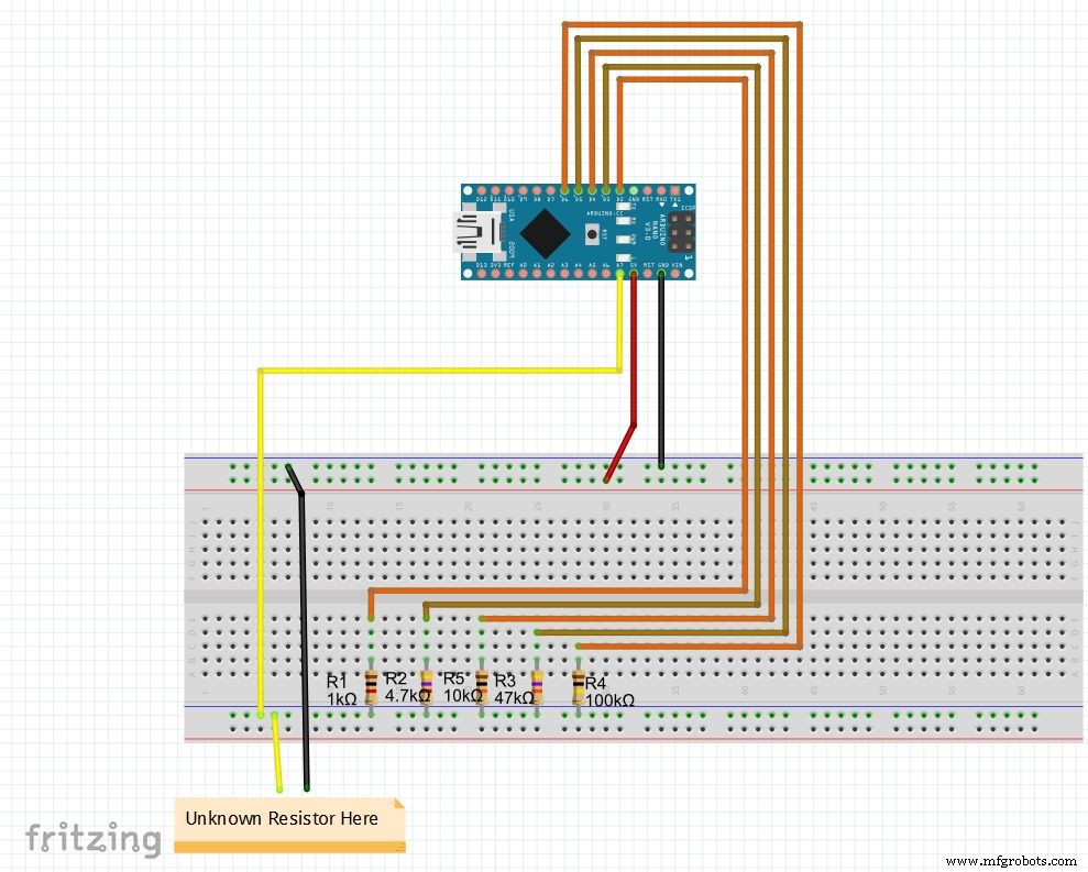
Nilai resistor dapat dimodifikasi, ubah nilai r1, r2, dll. Juga atur rentang (untuk rentang otomatis) yang sesuai. Lihat kode di bawah, unduh dari file di ujung dan uji ohmmeter pada papan tempat memotong roti
Jika Anda mengatur Nano untuk pertama kalinya, driver CH340G untuk itu dapat diunduh di sini, berfungsi dengan windows 7, 8, 8.1 dan 10. Pengguna Mac periksa di sini.
Pilih "Arduino Nano" di menu papan dan port COM yang benar. Unggah!
Kode
//Pin analog digunakan untuk mencari resistansiint Apin=7;//nilai r1 hingga r5float r1=1000;float r2=4700;float r3=10000;float r4=47000;float r5=100000;/ /pin dari r1 ke r5int r1_pin=2;int r2_pin=3;int r3_pin=4;int r4_pin=5;int r5_pin=6;float reading=0; //baca dari pin analog dan simpan di sinifloat R=0; //hitung yang tidak diketahui dan simpan di siniString finalR; //nilai akhir yang akan ditampilkan bersama dengan unitint caseno; //untuk debugging, menyimpan nomor kasus // kami membagi seluruh rentang menjadi kasus dan menetapkan masing-masing nomor, total 5 kasus // case1 :kurang dari 2850 // case2 :2850 hingga 7350 // case3 :7350 hingga 28500 // case4 :28500 hingga 73500 // case5 :lebih dari 73500#include // diperlukan untuk mengubah float menjadi string, memiliki fungsi String(float,n). Dijelaskan di bawah ini.void setup() { Serial.begin(9600);}void loop() { //pertama kita menemukan resistansi yang tidak diketahui menggunakan resistor 1kOhm //Oleh karena itu, nonaktifkan R2, R3, R4 dan R5 digitalWrite(r2_pin, LOW); //ubah setiap pin ke LOW sebelum menyetelnya sebagai INPUT pinMode(r2_pin, INPUT); // memutarnya INPUT saat HIGH mengaktifkan resistor pullup internal digitalWrite(r3_pin, LOW); pinMode(r3_pin, INPUT); digitalWrite(r4_pin, RENDAH); pinMode(r4_pin, INPUT); digitalWrite(r5_pin, RENDAH); pinMode(r5_pin, INPUT); pinMode(r1_pin, OUTPUT); digitalWrite(r1_pin, TINGGI); //membaca dan menghitung resistansi membaca=analogRead(Apin); R=(membaca*r1)/(1023-membaca); // jika nilai <2850, finalR =nilai(menggunakan 1kOhm) if(R<2850){ caseno=1; if(R<1000){ //jika nilai kurang dari 1000 gunakan "Ohm" bukan "kOhm" finalR =String(R,2) + "Ohm"; //String(float,n) Mengubah float menjadi string dengan n digit setelah desimal // melampirkan "Ohm" setelah nilai ke string, '+' menggabungkan dua string di sini } else{ //gunakan "kOhm R=R/1000; finalR =String(R,2) + "kOhm"; } } //jika nilai antara 2850 dan 7350 , gunakan nilai yang diperoleh 4.7kOhm else if(R>=2850 &&R<7350){ caseno=2; digitalWrite(r1_pin , LOW); //Aktifkan hanya 4,7kOhm pinMode(r1_pin, INPUT); digitalWrite(r3_pin, LOW); pinMode(r3_pin, INPUT); digitalWrite(r4_pin, LOW); pinMode(r4_pin, INPUT); digitalWrite(r5_pin, LOW ); pinMode(r5_pin, INPUT); pinMode(r2_pin, OUTPUT); digitalWrite(r2_pin, HIGH); reading=analogRead(Apin); R=(membaca*r2)/(1023-membaca)/1000; finalR =String( R,2) + "kOhm"; } //jika nilai antara 7350 dan 28500, gunakan nilai yang diperoleh dengan 10kOhm else if(R>=7350 &&R<28500){ caseno=3; digitalWrite(r1_pin, LOW); pinMode( r1_pin, INPUT); digitalWrite(r2_pin, LOW); pinMode(r2_pin, INPUT); digitalWrite(r4_pin, LOW); pinMode(r4_pin, INPUT); digitalWrite(r5_pin, LOW); pinMode(r5_pin, INPUT); pinM ode(r3_pin, OUTPUT); digitalWrite(r3_pin, TINGGI); membaca=analogBaca(Apin); R=(membaca*r3)/(1023-membaca)/1000; finalR=String(R,2) + "kOhm"; } //jika nilai antara 28500 dan 73500, gunakan nilai yang diperoleh 47kOhm else if(R>=28500 &&R<73500){ caseno=4; digitalWrite(r1_pin, RENDAH); pinMode(r1_pin, INPUT); digitalWrite(r2_pin, RENDAH); pinMode(r2_pin, INPUT); digitalWrite(r3_pin, RENDAH); pinMode(r3_pin, INPUT); digitalWrite(r5_pin, RENDAH); pinMode(r5_pin, INPUT); pinMode(r4_pin, OUTPUT); digitalWrite(r4_pin, TINGGI); membaca=analogBaca(Apin); R=(membaca*r4)/(1023-membaca)/1000; finalR =String(R,2) + "kOhm"; } //jika nilainya lebih dari 73500, gunakan nilai yang diperoleh 100kOhm else if(R>=73500){ caseno=5; digitalWrite(r1_pin, RENDAH); pinMode(r1_pin, INPUT); digitalWrite(r2_pin, RENDAH); pinMode(r2_pin, INPUT); digitalWrite(r3_pin, RENDAH); pinMode(r3_pin, INPUT); digitalWrite(r4_pin, RENDAH); pinMode(r4_pin, INPUT); pinMode(r5_pin, OUTPUT); digitalWrite(r5_pin, TINGGI); membaca=analogBaca(Apin); R=(membaca*r5)/(1023-membaca)/1000; finalR =String(R,2) + "kOhm"; } Serial.println(finalR); //mencetak string terakhir dengan unit Serial.println(" "); delay(1000);}
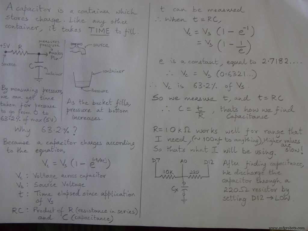
Langkah 3:Pengukur Kapasitansi - Konsep

Kode
/* RCTiming_capacitance_meter * konsep kode diambil dari Paul Badger 2008 * * Tegangan kapasitor pada satu waktu konstan didefinisikan sebagai 63,2% dari tegangan pengisian. * yaitu, Kapasitor diisi hingga 63,2% dari total kapasitasnya dalam 1 Konstanta Waktu */ int analogPin=0; // pin analog untuk mengukur tegangan kapasitor int chargePin=7; // pin untuk mengisi kapasitor - terhubung ke salah satu ujung resistor pengisian int dischargePin=12; // pin untuk melepaskan kapasitor, sama dengan yang digunakan untuk tes dioda (chechPin1) float resistorValue=10000.0; // Kami menggunakan resistor 10kOhm unsigned long startTime; unsigned long elapsedTime; float mikroFarad; // variabel floating point untuk menjaga presisi, membuat perhitungan float nanoFarads;void setup(){ pinMode(chargePin, OUTPUT); // setel chargePin ke output digitalWrite(chargePin, LOW); Serial.begin(9600); // menginisialisasi transmisi serial untuk debugging}void loop(){ digitalWrite(chargePin, HIGH); // set chargePin HIGH dan pengisian kapasitor startTime =milis(); while(analogRead(analogPin) <648){ // 647 adalah 63,2% dari 1023, yang sesuai dengan tegangan skala penuh } elapsedTime=milis() - startTime; // mengkonversi milidetik ke detik ( 10^-3) dan Farad ke microFarads ( 10^6 ), net 10^3 (1000) microFarads =((float)elapsedTime / resistorValue) * 1000; // (float) mengonversi waktu berlalu "unsigned long" menjadi float Serial.print(elapsedTime); // mencetak nilai ke port serial Serial.print(" mS "); // print unit if (microFarads> 1){ Serial.print((long)microFarads); // mencetak nilai ke serial port Serial.println(" microFarads"); // print unit } else { // jika nilainya lebih kecil dari satu mikroFarad, konversikan ke nanoFarad (10^-9 Farad). nanoFarad =mikroFarad * 1000,0; // kalikan dengan 1000 untuk mengkonversi ke nanoFarad (10^-9 Farads) Serial.print((long)nanoFarads); // print nilai ke serial port Serial.println(" nanoFarads"); // print unit } /* isi kapasitor */ digitalWrite(chargePin, LOW); // setel pin charge ke LOW pinMode(dischargePin, OUTPUT); // setel pin debit ke output digitalWrite(dischargePin, LOW); // setel debit pin LOW while(analogRead(analogPin)> 0){ // tunggu sampai kapasitor benar-benar habis } pinMode(dischargePin, INPUT); // setel pin pelepasan kembali ke input}
Langkah 4:Uji Dioda
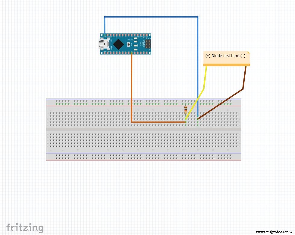
Pin analog ditarik hingga 5V dengan resistor 10k Ohm. Jadi pin analog membaca 1023 ketika tidak ada yang terhubung. H12 diatur ke OUTPUT , RENDAH .
Ketika dioda diberi bias maju antara pin analog (5V ) dan H12 (GND ), pin analog membaca 100-400 .
Ketika dibias mundur, praktis arus yang mengalir sangat kecil dan pin analog membaca 900-1023 .
Dengan cara ini kita dapat dengan mudah mengetahui sisi p dan n dari sembarang dioda. Ini dapat digunakan untuk memeriksa LED dan dioda dengan cepat.
Kode
String state ="null";int checkPin1 =12;int checkPin2 =6;void setup() { Serial.begin(9600);}void loop() {pinMode(checkPin1, OUTPUT); digitalWrite(checkPin1, RENDAH); //pin 11 disetel ke rendah//pembacaan analog biasanya ditarik oleh resistor 10k, jadi pembacaan nol adalah 1023//Dalam bias maju, pin analog terhubung ke checkPin1, yang LOW. Jadi membaca kurang dari 1023// Praktis arus kecil mengalir dalam bias terbalik juga, jadi kami mengambil 700 untuk membedakan if(analogRead(checkPin2)<700){ state="forward"; } Serial.println(status); Serial.println(analogRead(checkPin2)); status ="nol"; delay(500);}
Langkah 5:Jam Waktu Nyata (RTC)
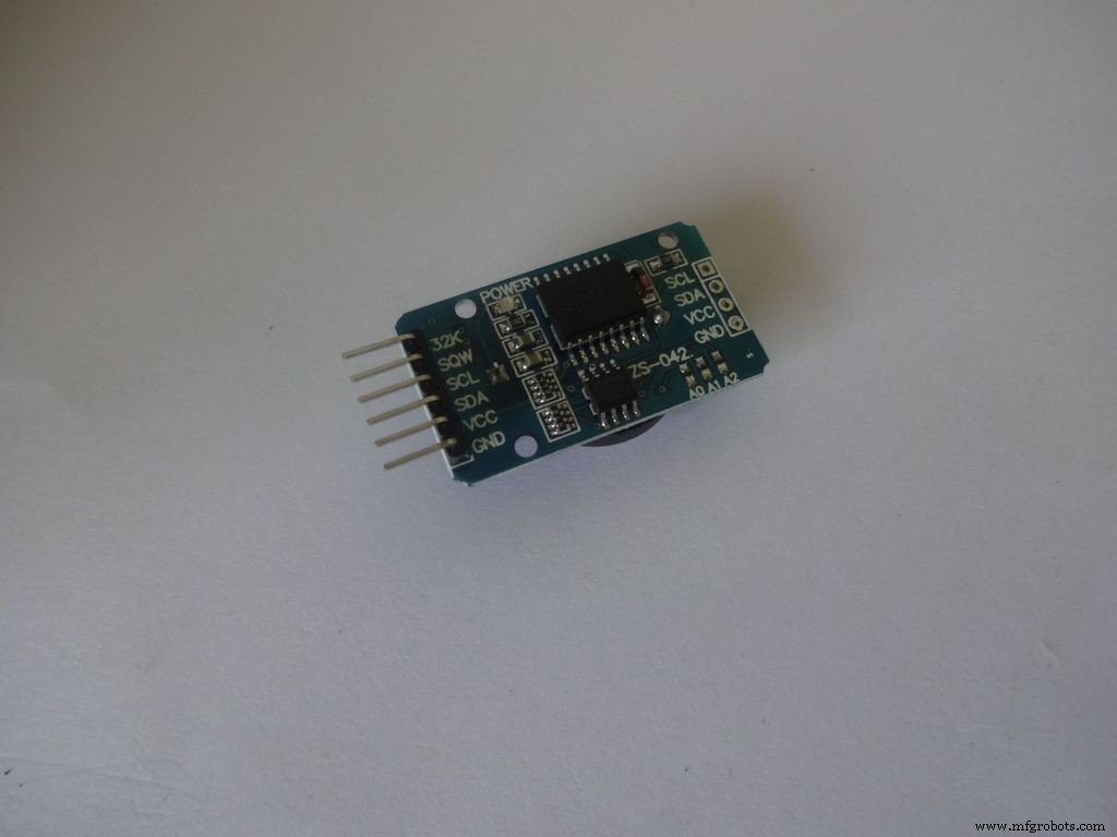
RTC menyimpan informasi detik, menit, jam, hari, tanggal, bulan, dan tahun. Itu terus menghitung bahkan ketika daya eksternal dihilangkan berkat sel koin kecil di dalamnya. Tanggal di akhir bulan secara otomatis disesuaikan untuk bulan dengan kurang dari 31 hari, termasuk koreksi untuk tahun kabisat.
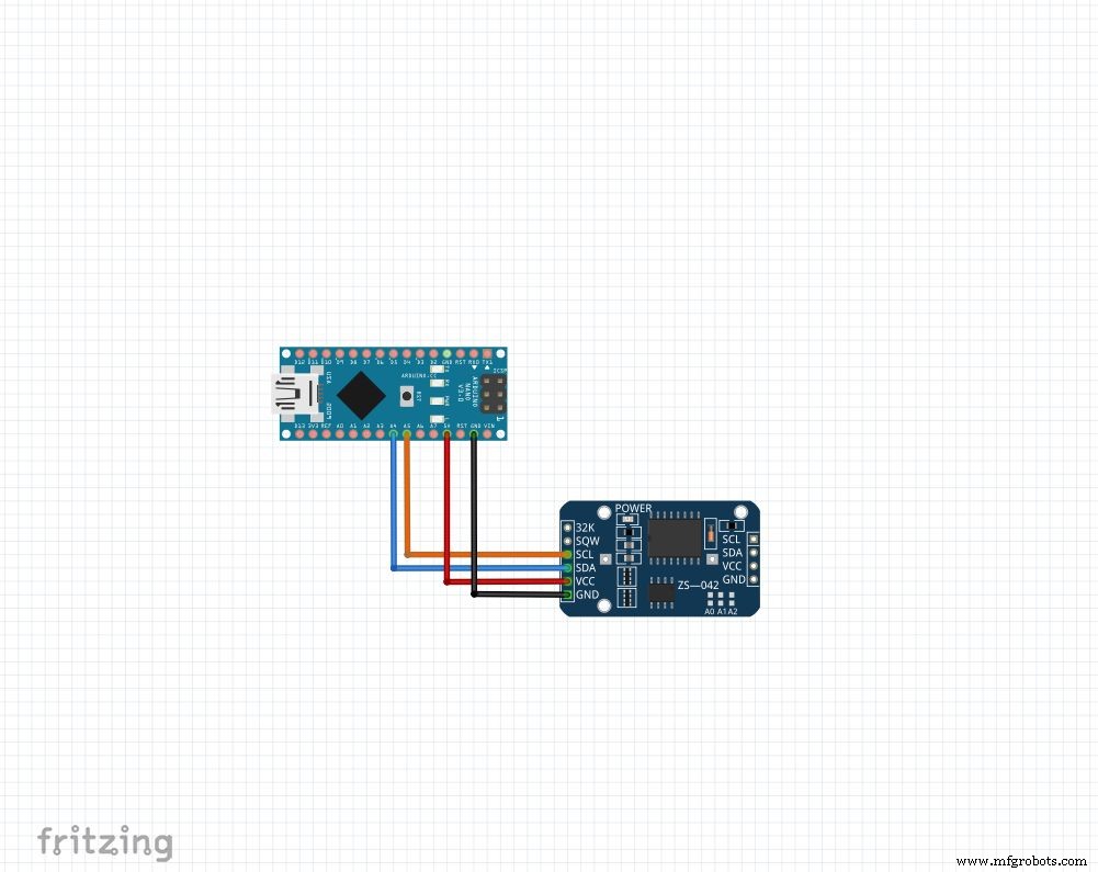
Modul apa pun yang Anda miliki, kami akan menggunakan 4 pin:Vcc , GND , SDA dan SCL . SDA dan SCL pin pada arduino nano dan uno adalah A4 dan A5 masing-masing. Untuk arduino lain, googling!
Kami akan menggunakan perpustakaan "RTClib", yang membuat pengaturan dan akses waktu menjadi sangat mudah! Pustaka dapat diunduh di sini (Klik "Unduh ZIP", dan ekstrak "RTClib-master" di folder pustaka Arduino Anda. Selengkapnya tentang memasang pustaka.)
Untuk menyetel waktu, unduh "RTC_set_time.ino" yang dilampirkan pada langkah ini dan batalkan komentar pada baris,
rtc.adjust(DateTime(F(__DATE__), F(__TIME__)));
Jika Anda ingin menggunakan waktu yang diatur di komputer Anda saat kompilasi. Atau
rtc.adjust(DateTime(2014, 1, 21, 3, 0, 0)); //tahun, bulan, tanggal, jam, menit, detik
Untuk mengatur waktu kustom.
Hubungkan seperti yang ditunjukkan dan unggah. Buka Serial monitor pada 9600 baud untuk melihat waktu saat ini. Periksa lagi setelah beberapa jam untuk melihat perkembangan RTC.
Pastikan Anda merekomendasikan baris ini dan mengunggah lagi setelah menyetel waktu sekali. Atau Anda akan terus menyetel ulang setiap kali Arduino disetel ulang!
Kode
// Fungsi tanggal dan waktu menggunakan RTC DS1307 yang terhubung melalui I2C dan Wire lib#include #include RTC_DS1307 rtc;//membuat objek "rtc" dari RTC_DS1307, objek digunakan untuk mengakses fungsi //lebih lanjut tentang objek dan kelas:https://www.youtube.com/watch?v=ABRP_5RYhqUchar daysOfTheWeek[7][12] ={"Sunday", "Monday", "Selasa", " Rabu", "Kamis", "Jumat", "Sabtu"};pengaturan batal () { Serial.begin(9600); rtc.mulai(); // baris berikut menyetel RTC ke tanggal &waktu sketsa ini dikompilasi // rtc.adjust(DateTime(F(__DATE__), F(__TIME__))); // Baris ini menetapkan RTC dengan tanggal &waktu yang eksplisit, misalnya untuk menetapkan // 21 Januari 2014 pukul 3 pagi, Anda akan memanggil:// rtc.adjust(DateTime(2014, 1, 21, 3, 0, 0) );}void loop() { DateTime sekarang =rtc.now(); Serial.print(sekarang.tahun()); Serial.print('/'); Serial.print(sekarang.bulan()); Serial.print('/'); Serial.print(sekarang.hari()); Serial.print("("); Serial.print(hariPekan[sekarang.hariPekan(()]); Serial.print(") "); Serial.print(sekarang.jam()); Serial.print(':'); Serial.print(sekarang.menit()); Serial.print(':'); Serial.print(sekarang.detik()); Serial.println(); Serial.println(); delay(1000);}
Langkah 6:Penyiapan Akhir
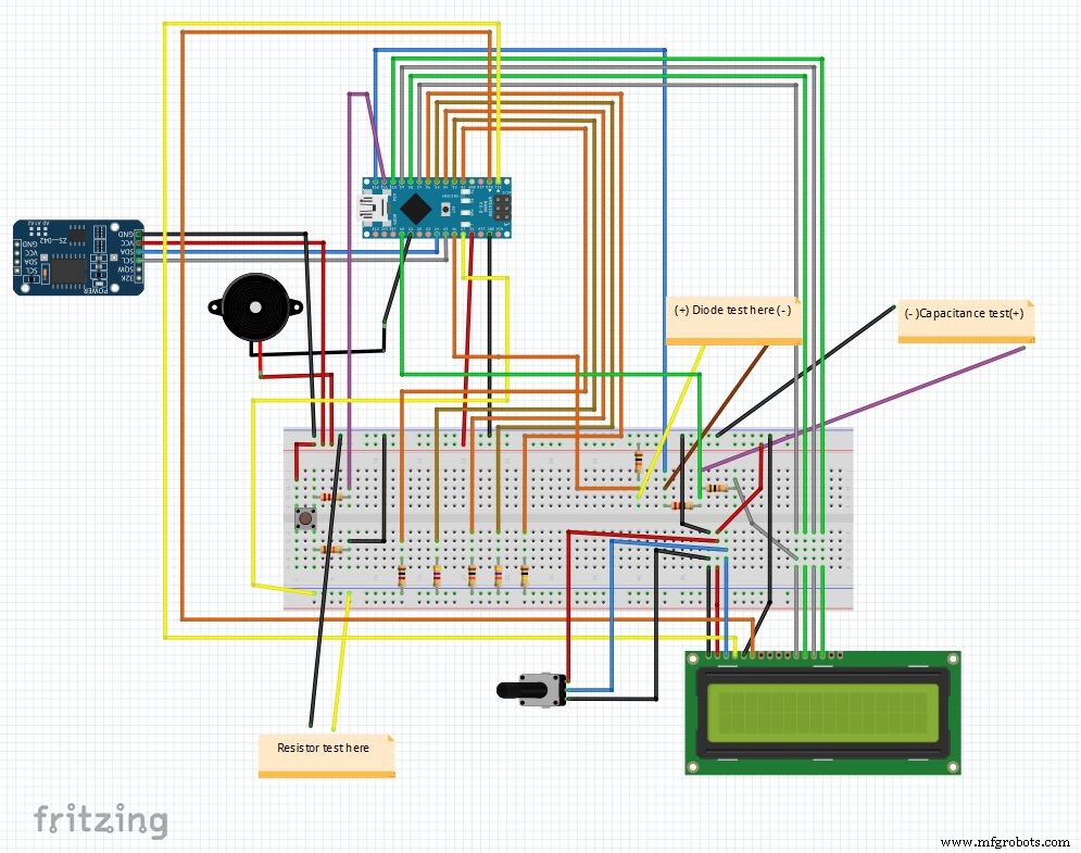
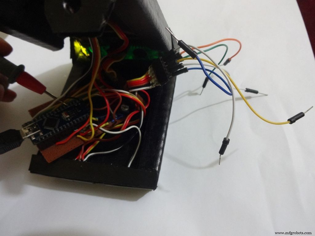
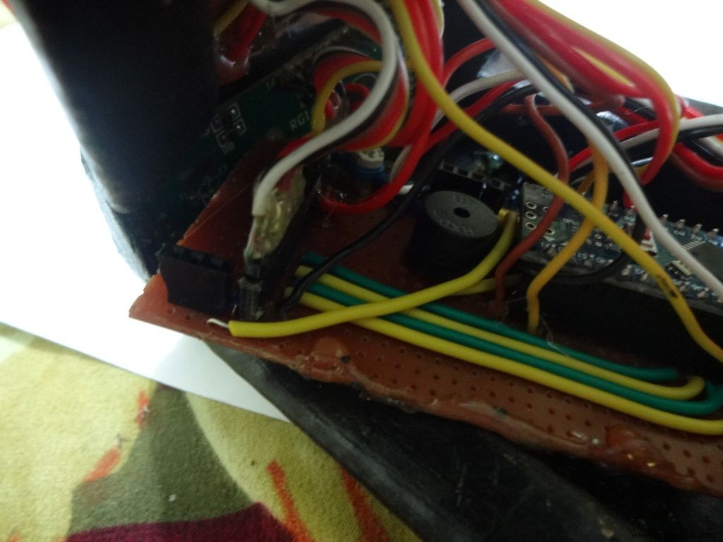
Jadi itulah rangkaian terakhir setelah menggabungkan semua elemen. Kode utama dan file fritzing terlampir di bagian akhir.
Unduh fritzing dari fritzing.org jika Anda belum melakukannya.
Ekstrak file Main_code.rar dan buka Main_file_rtc.ino. Saya telah memasukkan semua deklarasi variabel dalam definations.h . yang terpisah file header, itu akan ditambahkan secara otomatis ketika Anda membuka kode utama.
Bagian yang berbeda dibuat menjadi fungsi: Clock() , findResistance() , findCapcitance() dan diodeTest() . Ini ditulis dalam tab terpisah, membuat pembacaan menjadi mudah dan perubahan mudah diterapkan. File utama hanya memeriksa status "tombol mode" dan memanggil fungsi yang sesuai.
Detail lainnya dijelaskan dengan benar dalam kode itu sendiri.
Setelah uji coba di papan tempat memotong roti, kami siap untuk mulai membuat IC!
Catatan:Buzzer jika belum digunakan, dapat digunakan bila diperlukan, misalnya fungsi kontinuitas.
Langkah 7:Mempersiapkan sakelar
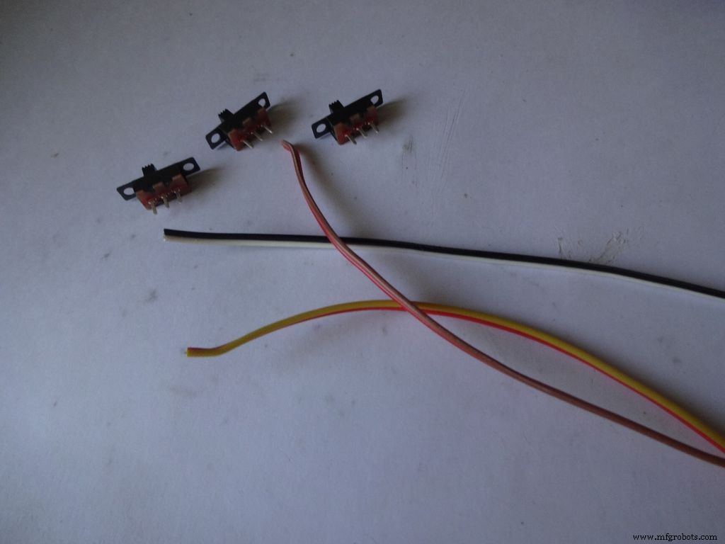
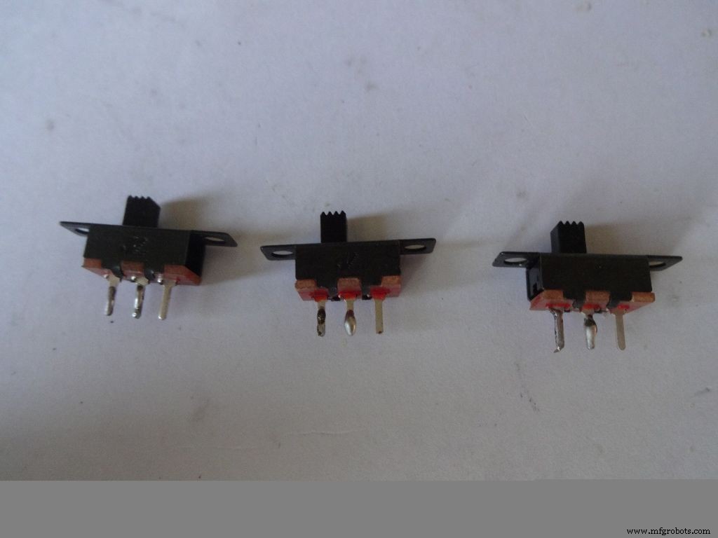


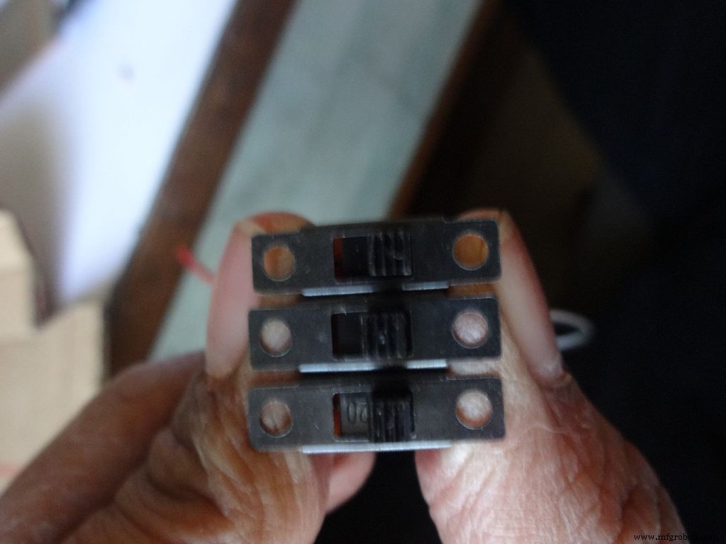
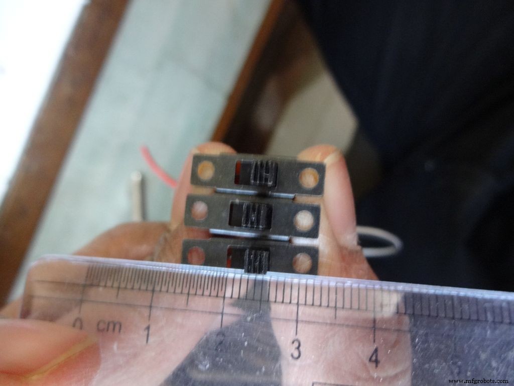
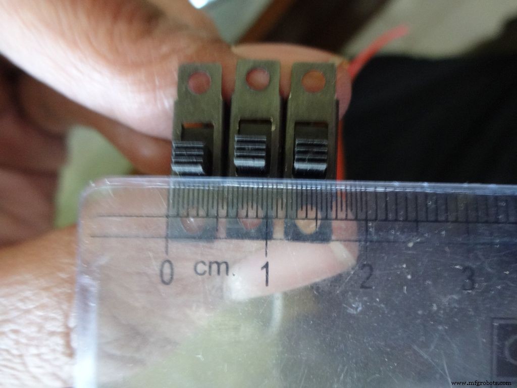
Ambil 3 sakelar geser bersama dengan 3 pasang kawat, panjangnya sekitar 10cm. Saya membagi kabel pita untuk ini.
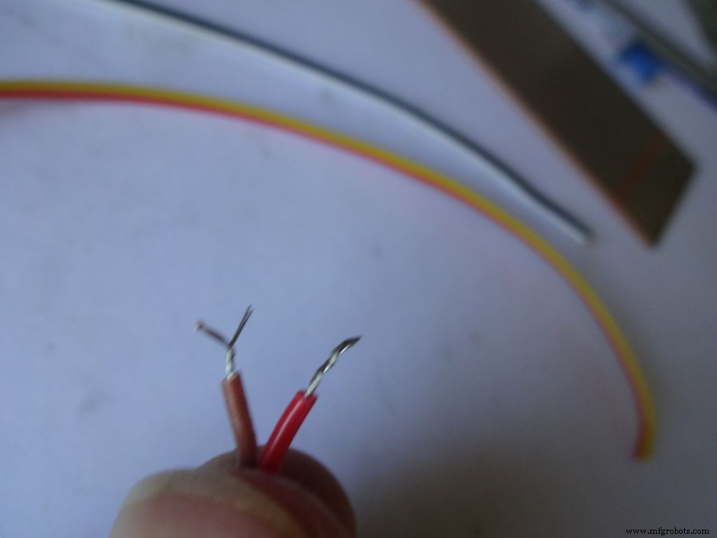
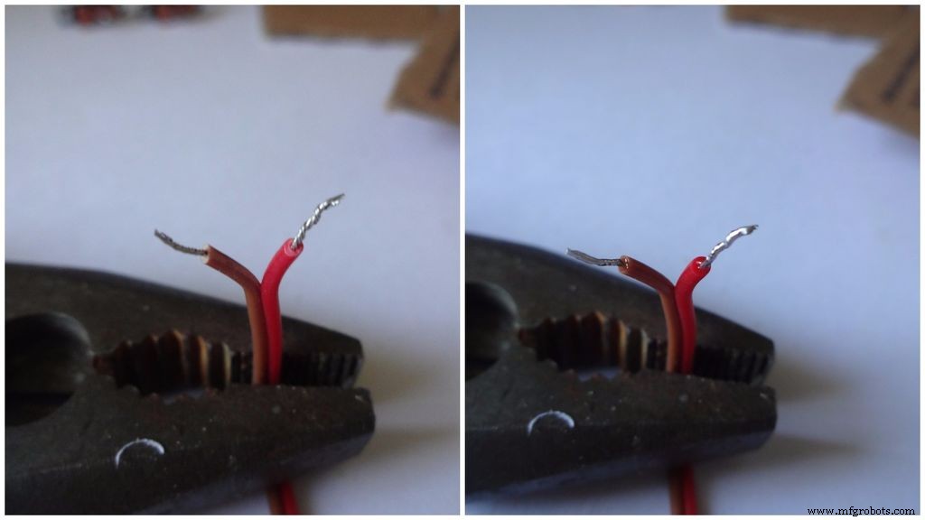
Lepaskan sebagian kecil insulasi (tidak lebih dari 5mm) dan putar untaiannya.
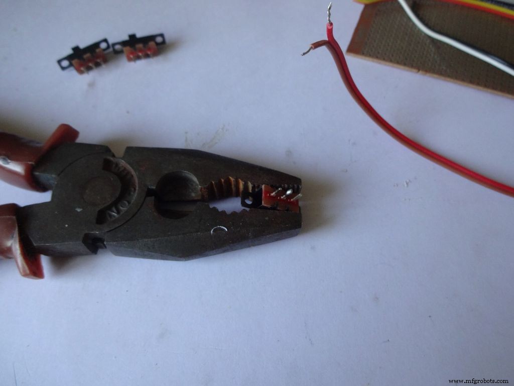
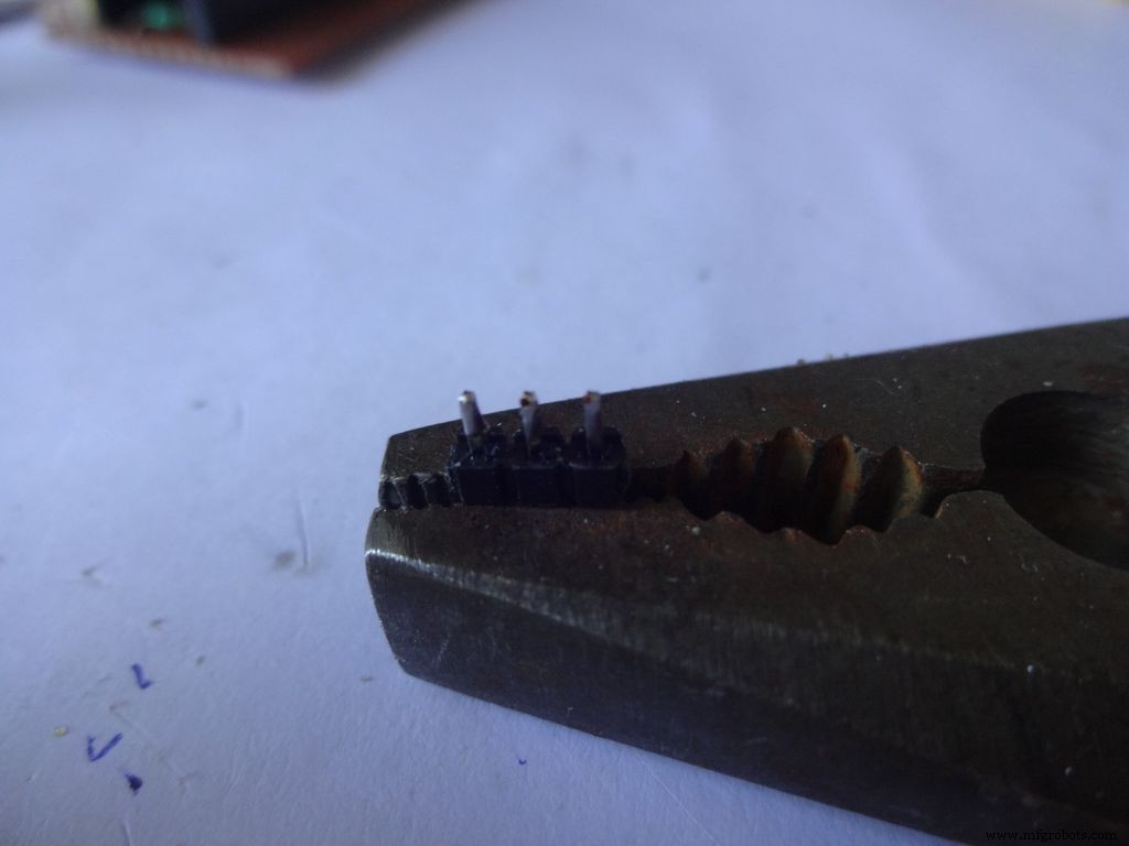
Oleskan beberapa solder ke 2 pin yang berdekatan dari masing-masing sakelar. Gunakan sesuatu untuk menahannya Di tempat saat Anda menyolder, saya menggunakan tang yang berat.
Jika Anda belum pernah menyolder sebelumnya, sekarang saat yang tepat untuk memulai. Youtube memiliki banyak sekali video tentang teknik Anda cara menyolder dengan benar. Pelajaran dari PACE sangat informatif, silakan ditonton.
Selanjutnya kita harus 'mengencangkan' kabelnya. Sentuh ujung besi solder ke kawat yang akan dikalengkan. Oleskan sedikit solder di antara ujung dan kawat, ini menciptakan jembatan yang menghantarkan panas dari ujung ke kawat. Kemudian Anda mengoleskan solder langsung ke kawat, di sisi berlawanan dari ujung besi solder . Lepaskan soldernya. Hapus ujungnya. Video tentang ini.
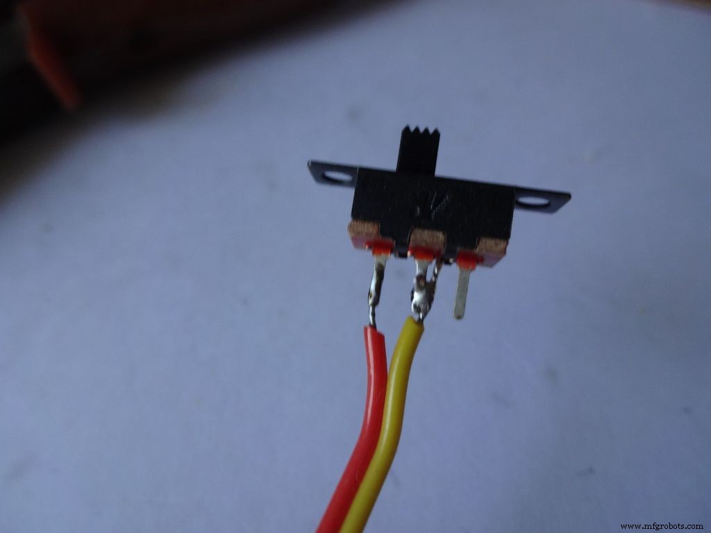
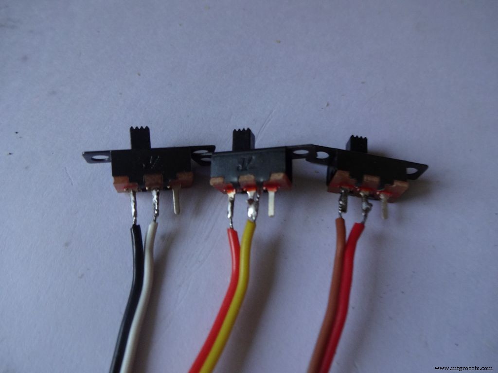
Setelah itu, tahan sakelar di tempatnya, bawa salah satu kawat timah ke pin dan pasang kembali solder dengan menyentuh besi solder. Lakukan hal yang sama dengan kabel kedua. Perhatikan bahwa saya meletakkan kabel berwarna gelap di satu sisi sakelar.
Sekarang ulangi prosedur dan pasang dua kabel ke tombol tekan (ini akan menjadi tombol reset). Pastikan Anda tidak memasang kabel ke ujung tombol yang terhubung secara normal.
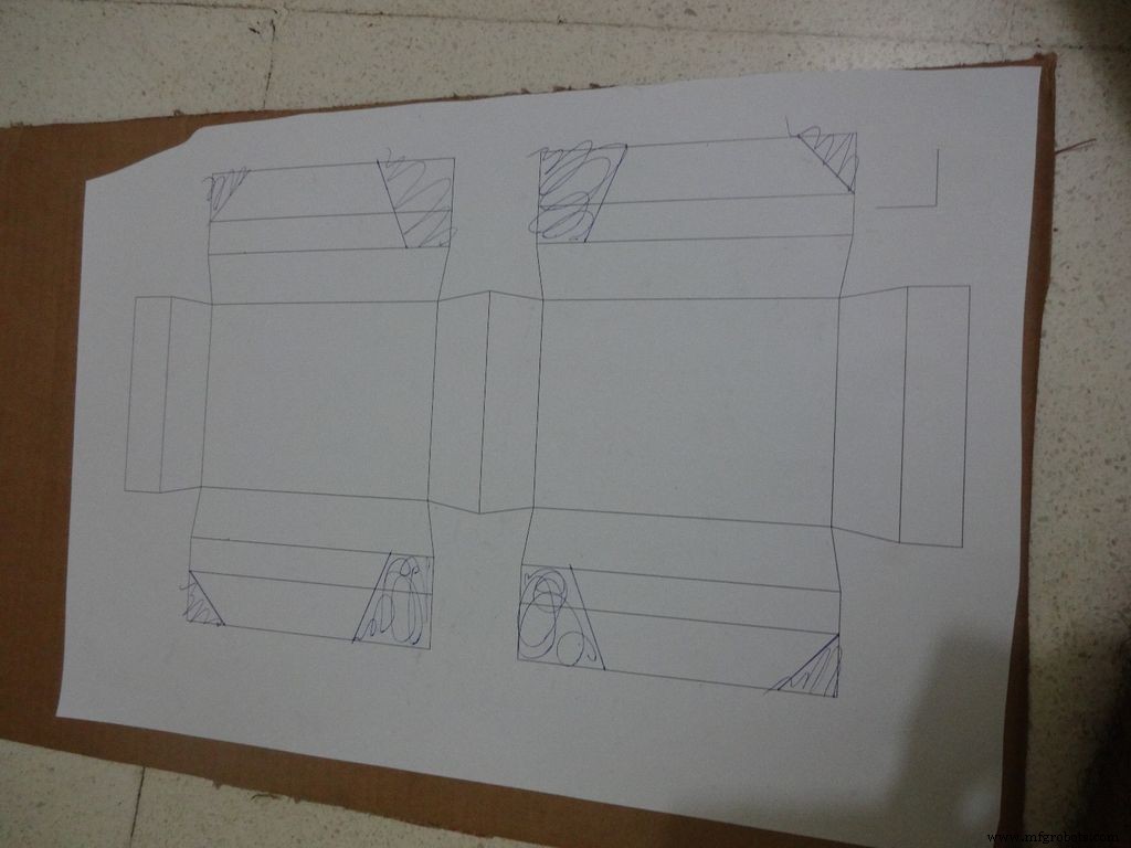
Langkah 8:Membuat Kasus - Memotong tata letak
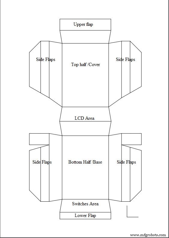
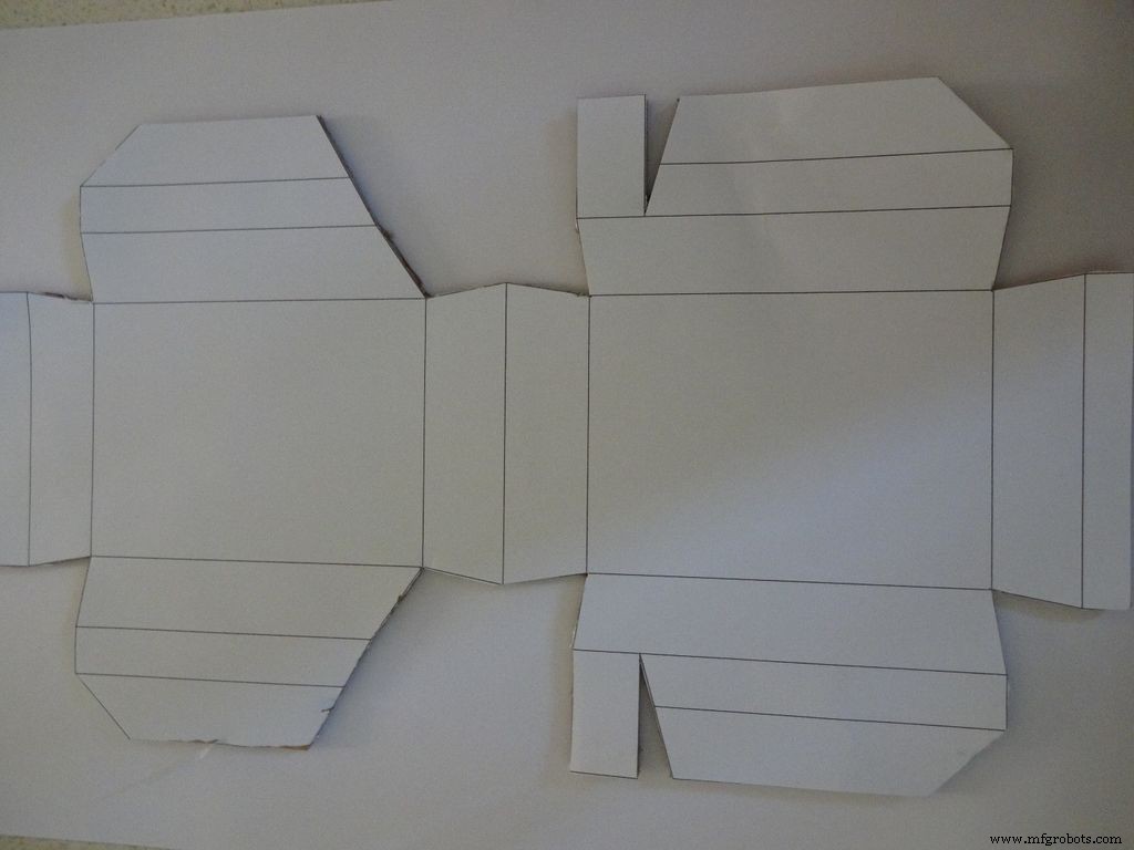
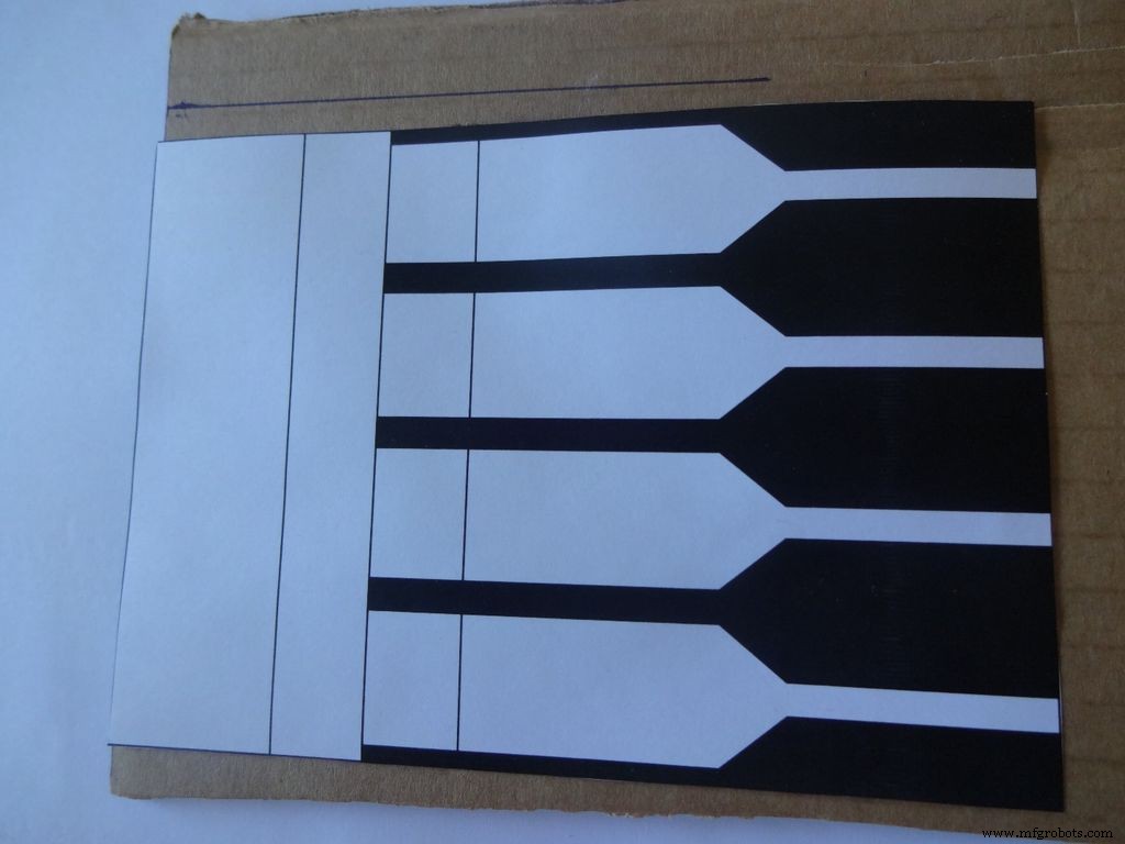
Unduh "Layout_Final_A3.pdf" atau ""Layout_Final_ANSI_B.pdf", berdasarkan ukuran kertas yang tersedia di wilayah Anda. terlampir di bagian akhir.
Cetak pada kertas ukuran A3 (29,7 x 42.0cm atau 11,69 x 16,53 inci) atau ANSI B alternatif AS (11 x 17 inci atau 279 × 432mm). Pastikan saat mencetak, Anda memilih ukuran kertas, orientasi, dan memilih opsi "Ukuran Sebenarnya". Pastikan hasil cetak akurat dengan mengukur sudut kanan kecil di sudut kanan bawah, seharusnya 2cm x 2cm.
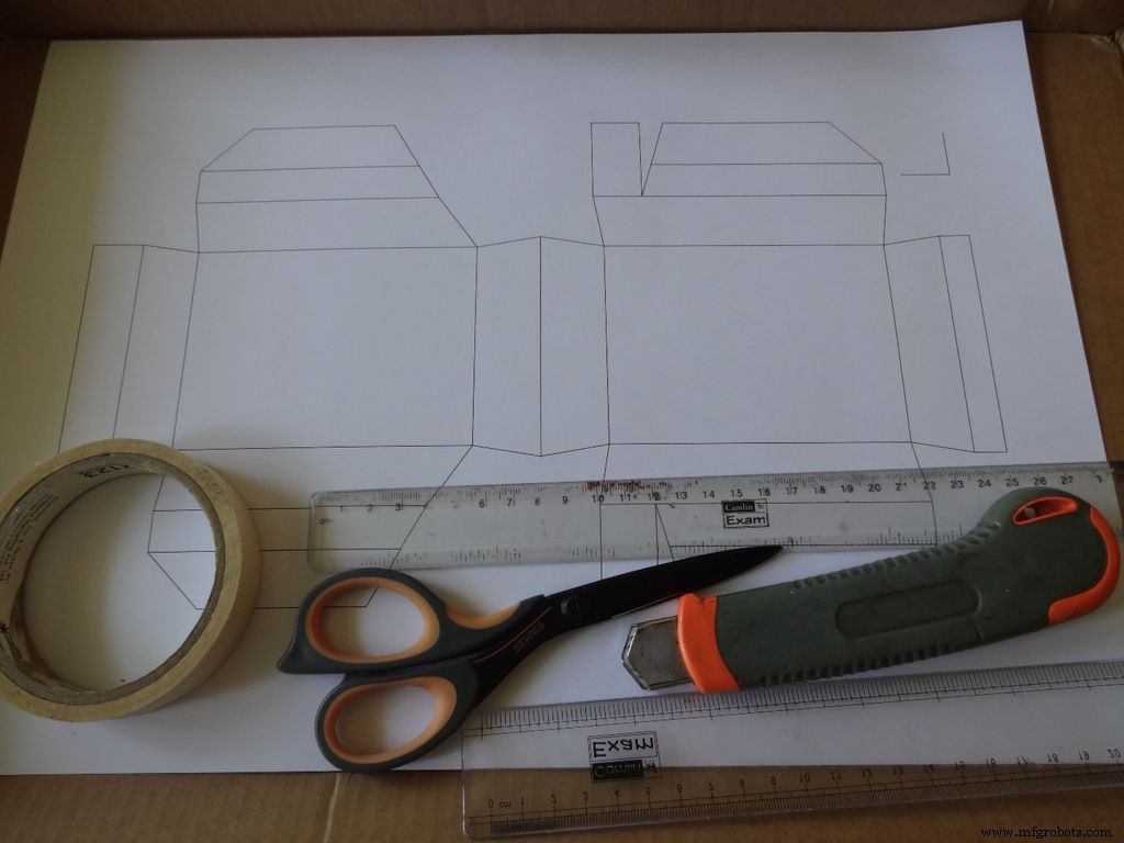
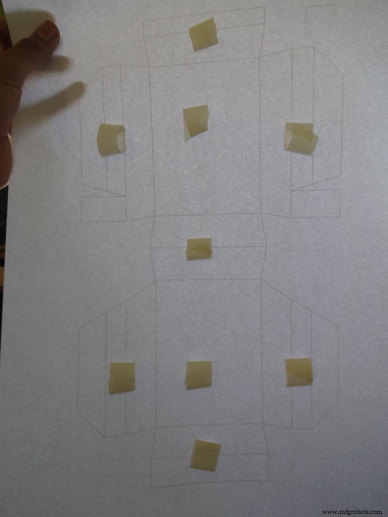
Potong selembar karton kira-kira lebih dari tata letaknya. Sobek selotip kecil, bentuk gulungan 'lengket dua sisi', dan tempelkan di tempat yang ditunjukkan. Kemudian tempelkan lembaran tersebut pada karton.
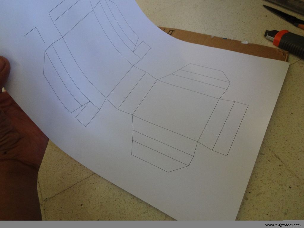
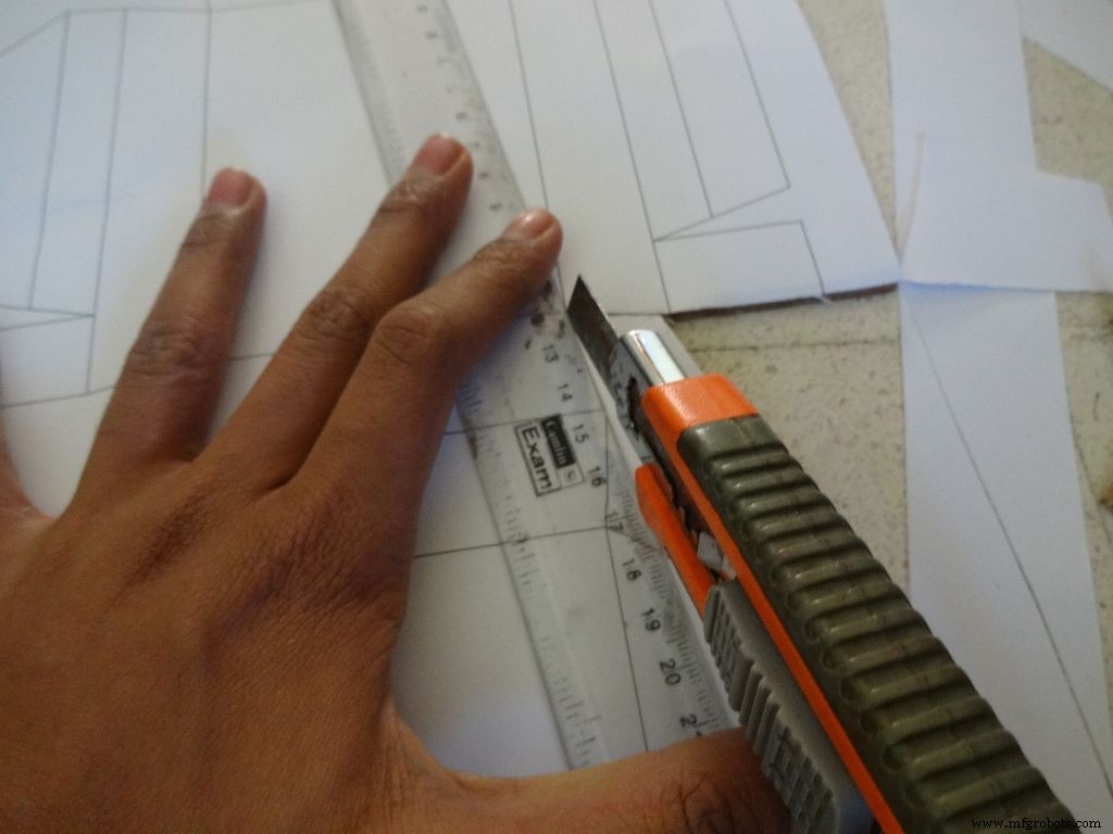
Gunakan gunting tajam atau pemotong kotak dengan penggaris untuk memotong batas luar tata letak kotak. Saya menemukan pemotong kotak jauh lebih baik daripada gunting. Sebagian besar pemotong memiliki bilah yang dapat dipatahkan secara bertahap untuk mendapatkan ujung yang segar dan tajam, jadi disarankan untuk melakukannya. Simpan selembar karton atau kayu lain di bawah bagian yang Anda potong, ini membantu mendapatkan potongan yang lebih bersih.
Juga, tidak menjaga penggaris dengan benar pada garis saat memotong adalah kesalahan umum. Jangan lakukan ini dengan terburu-buru.
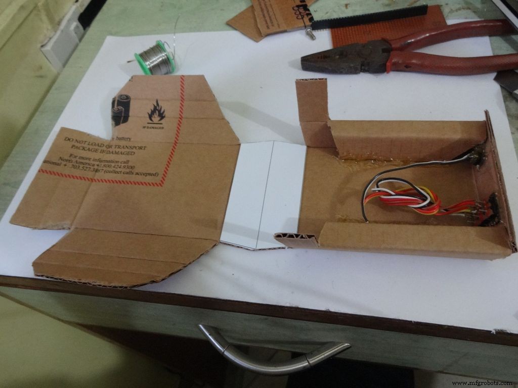
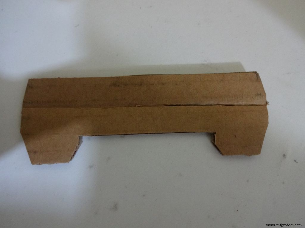
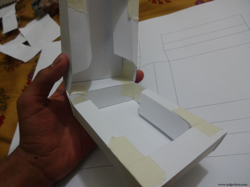
Langkah 9:Membuat Casing - Melipat dan Melipat
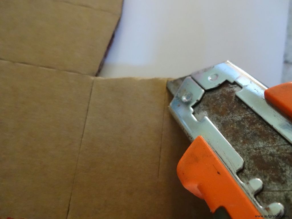
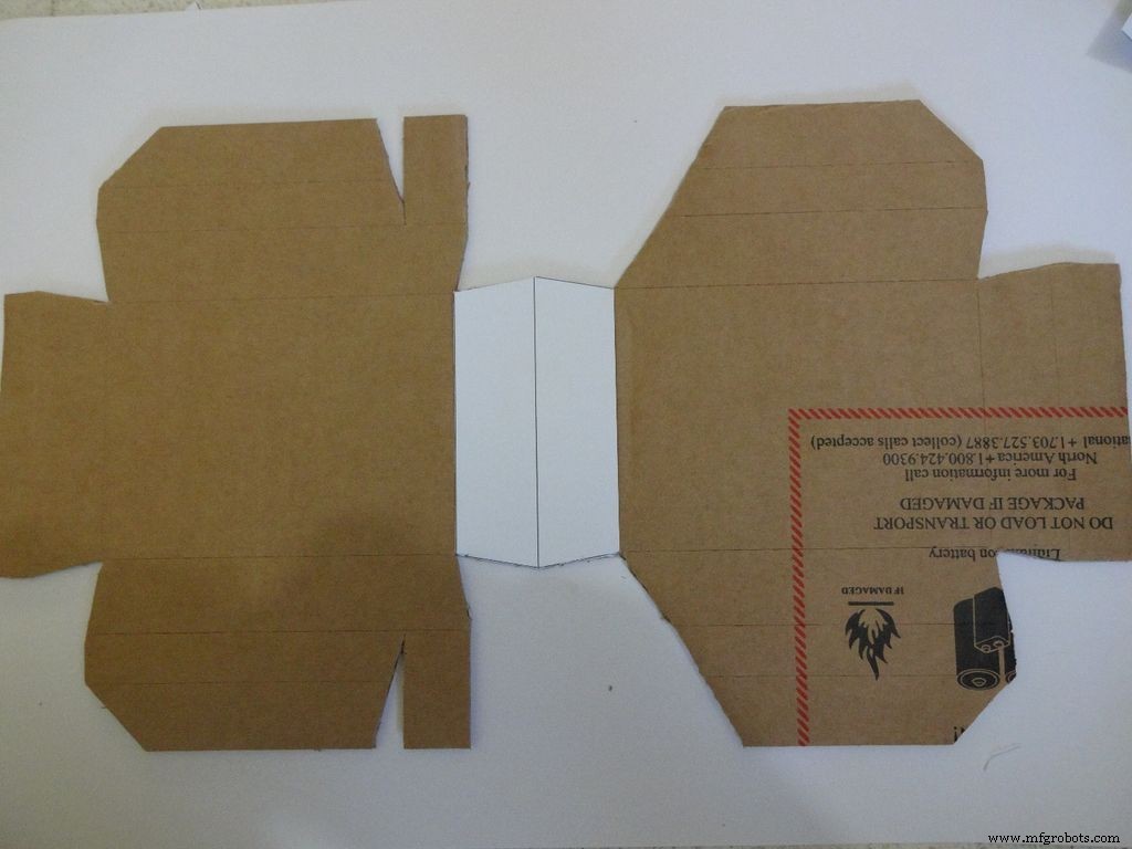
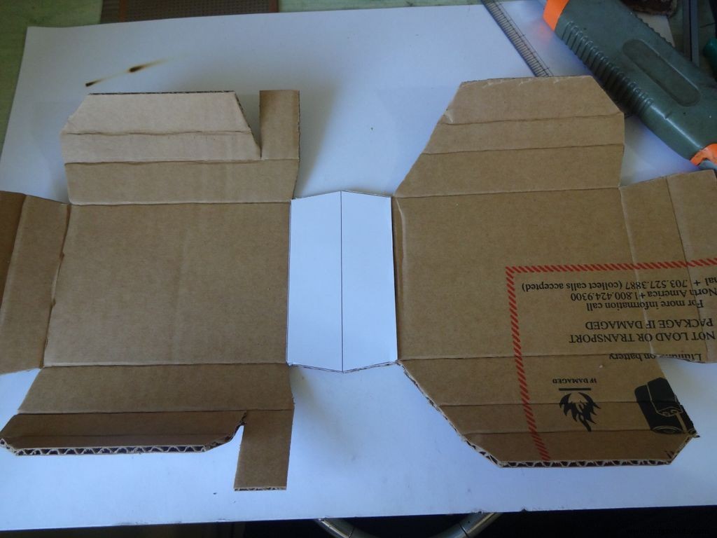


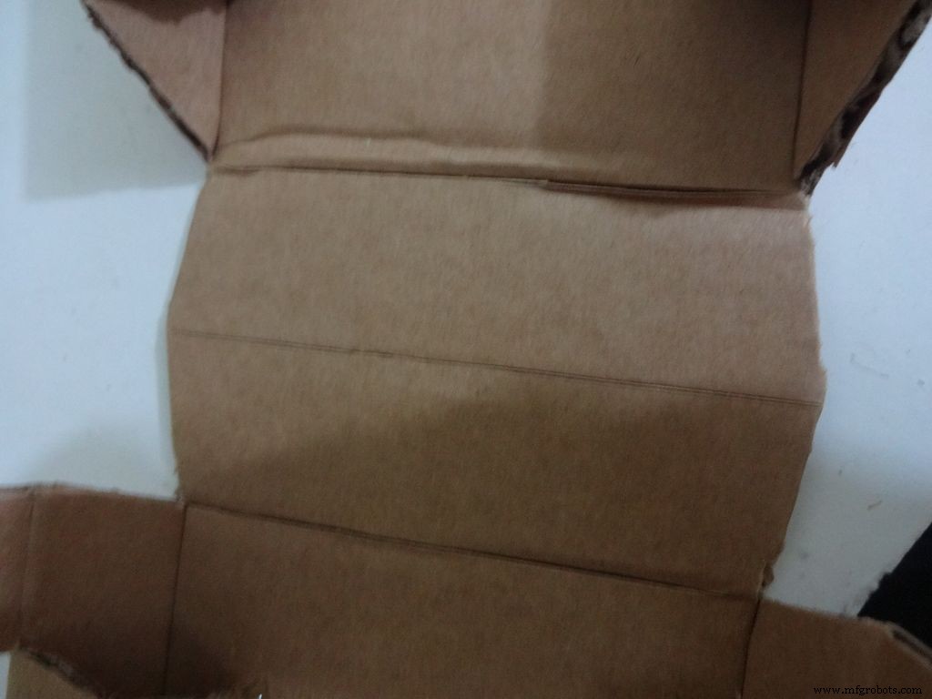
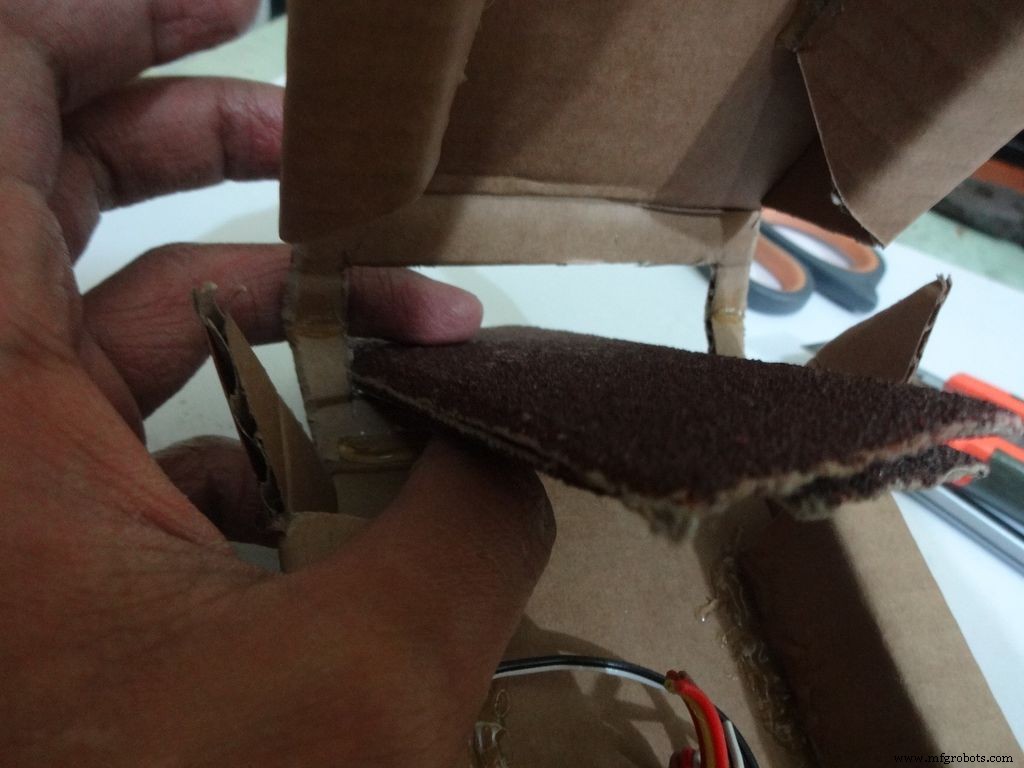
Menggunakan pemotong dengan timbangan, dengan hati-hati buat lipatan di sepanjang garis lipatan, kecuali garis tengah di Area LCD. Tekuk dan lipat semua bagian yang dapat dilipat dan perbaiki lipatan yang tidak lengkap.
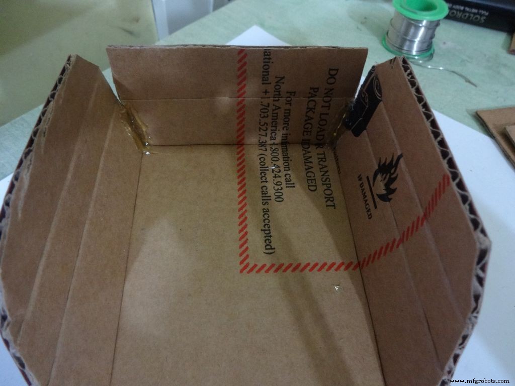
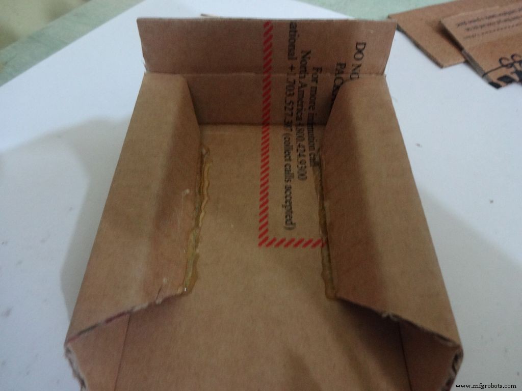
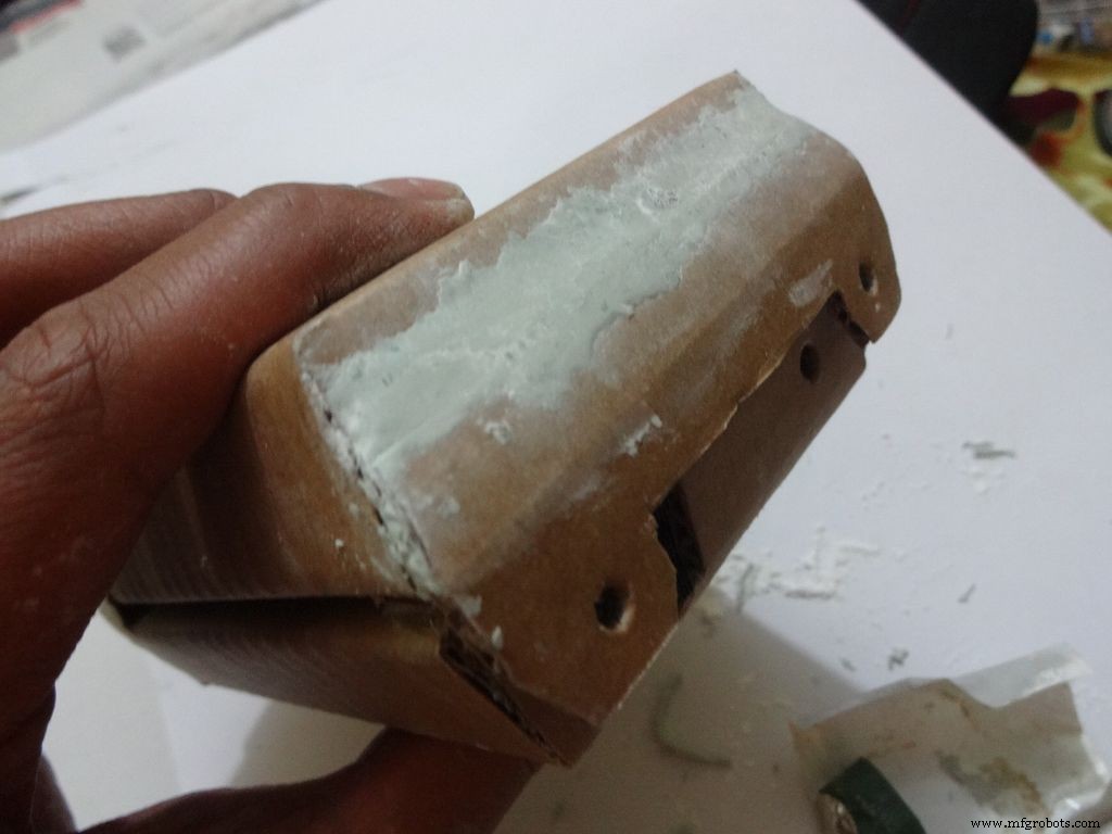
Untuk bagian bawah atau alas:
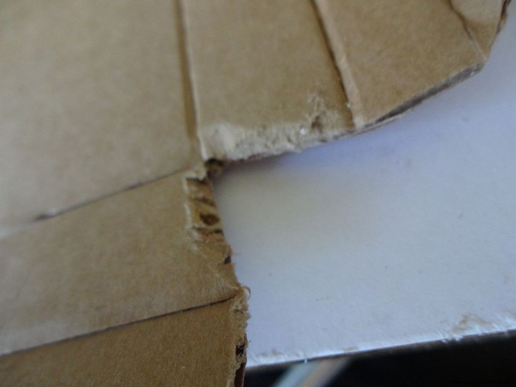
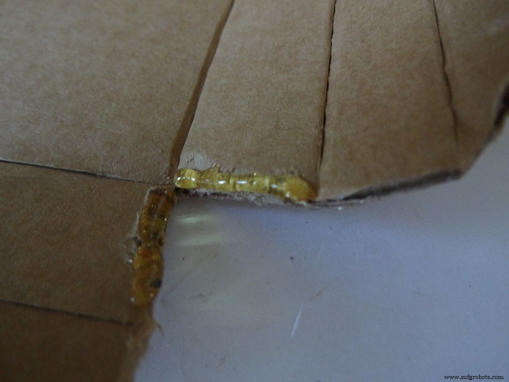
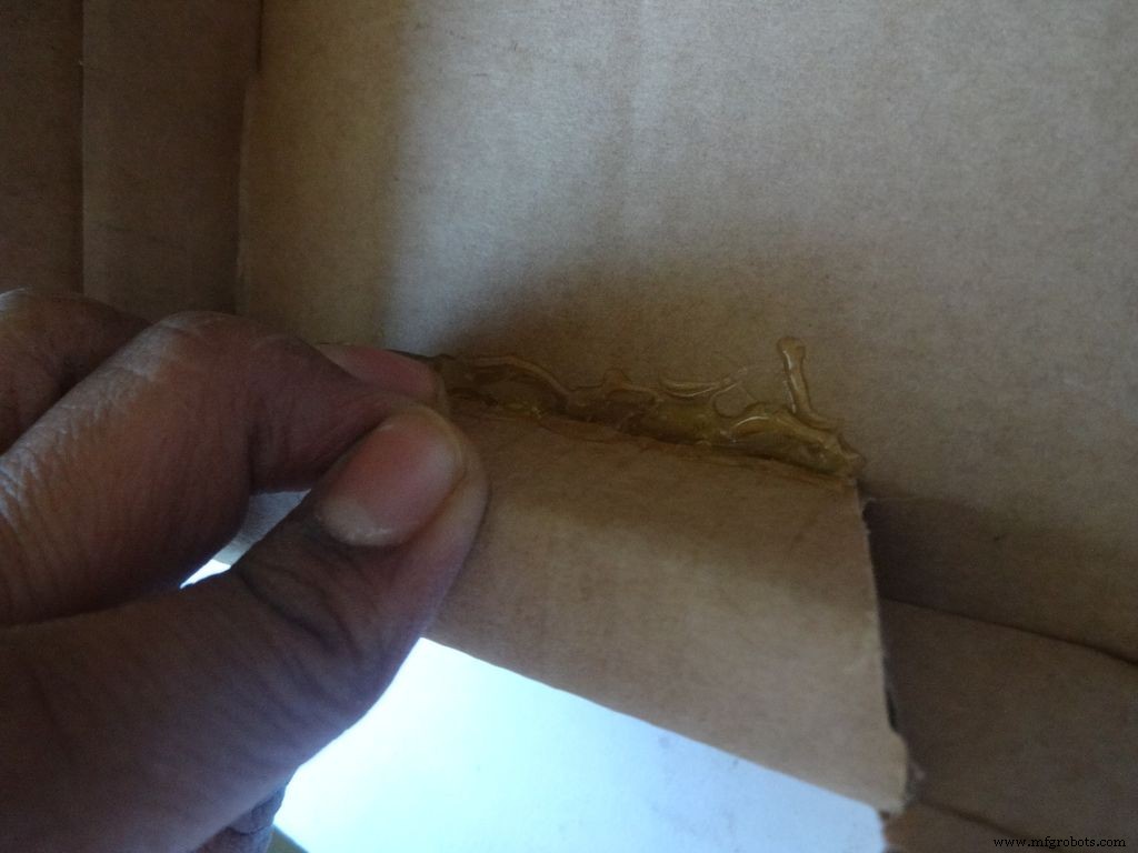
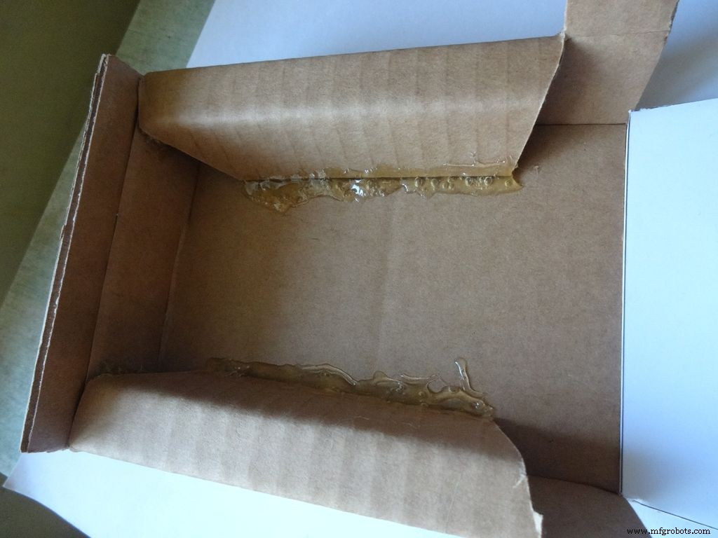
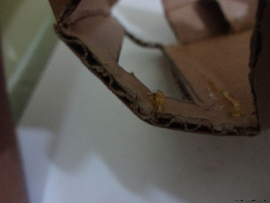
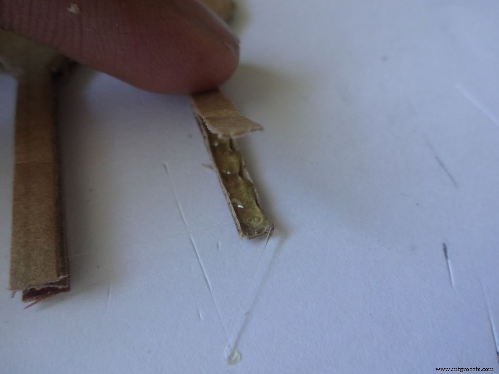
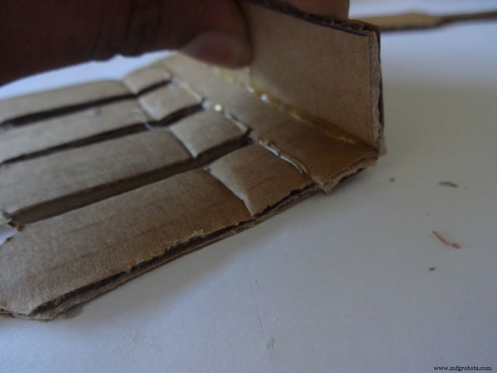
Dengan menggunakan amplas, amplas empat tepi pertama pada bidang miring, oleskan lem panas dengan pistol lem (satu sisi pada satu waktu), gabungkan dan tahan 30-60 detik saat lem menjadi dingin.
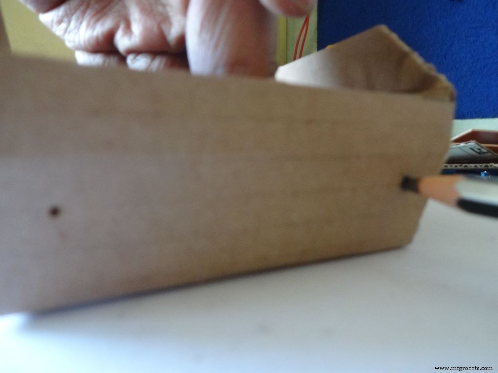
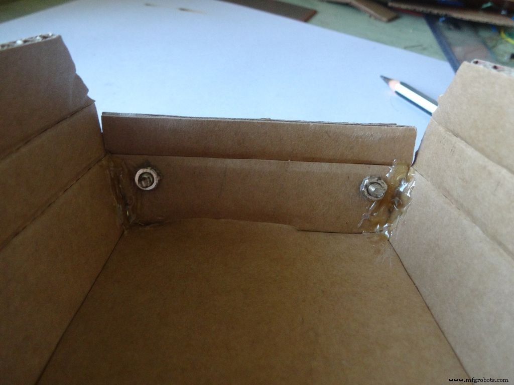
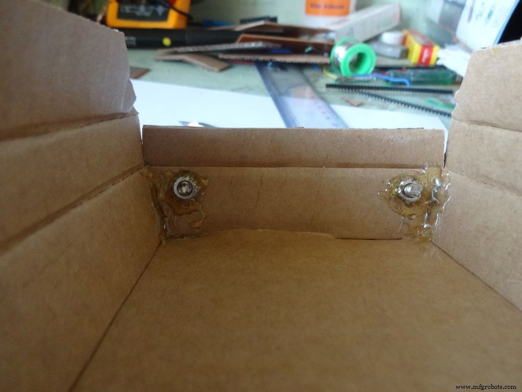
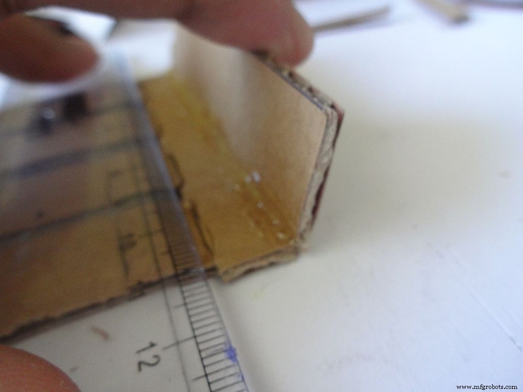
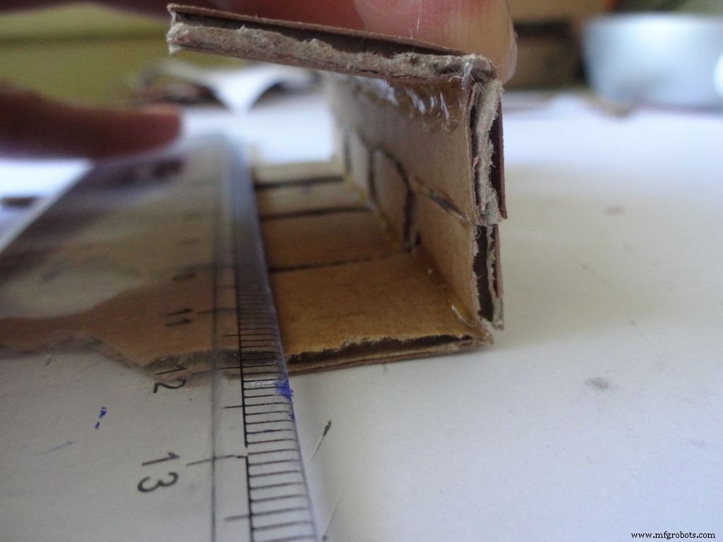
Buat dua lubang dengan pin jempol seperti yang ditunjukkan dan perbesar dengan pensil secukupnya agar pas dengan bautnya. Kencangkan mur di bagian dalam, oleskan lem panas (tepat di mur!), biarkan dingin. Lepaskan baut dengan obeng.
Selanjutnya, lipat kedua penutup samping ke dalam dan tempelkan. Bagian luar penutup harus sedikit miring dan bagian tengahnya rata.
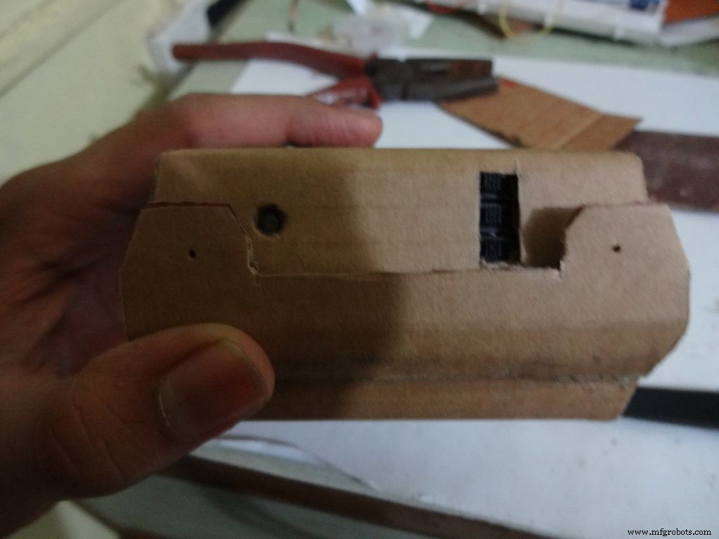
Langkah 10:Membuat casing - Menambahkan sakelar
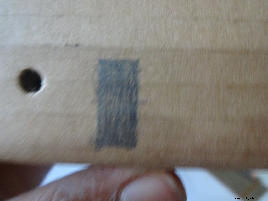
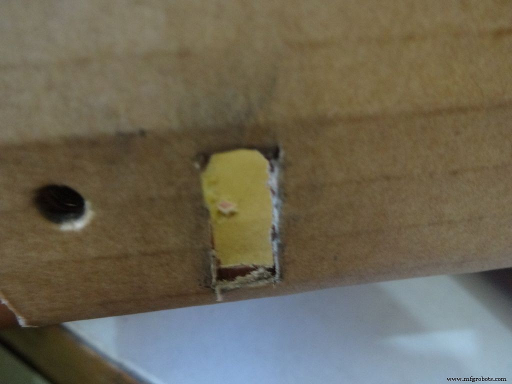
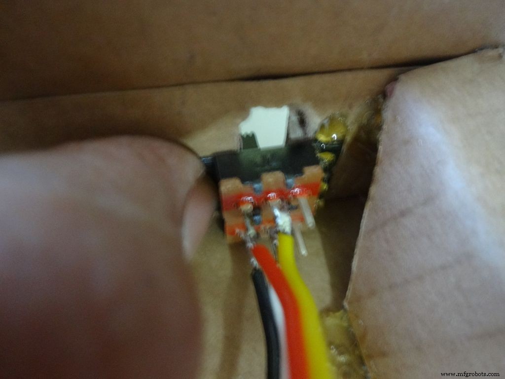
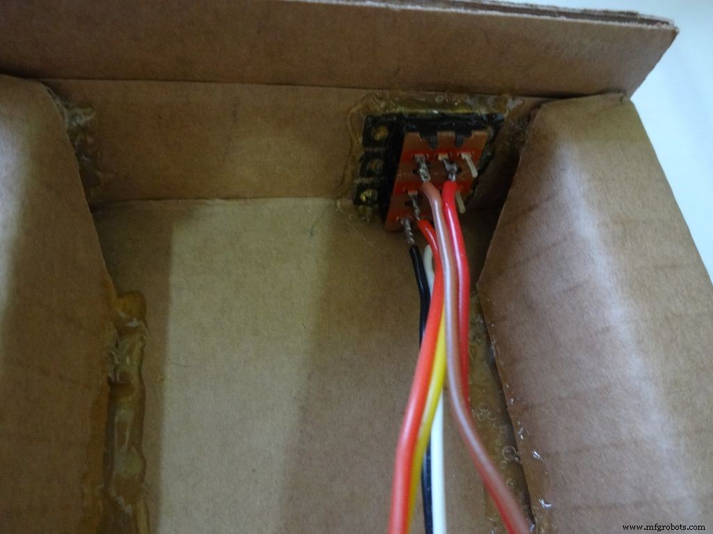
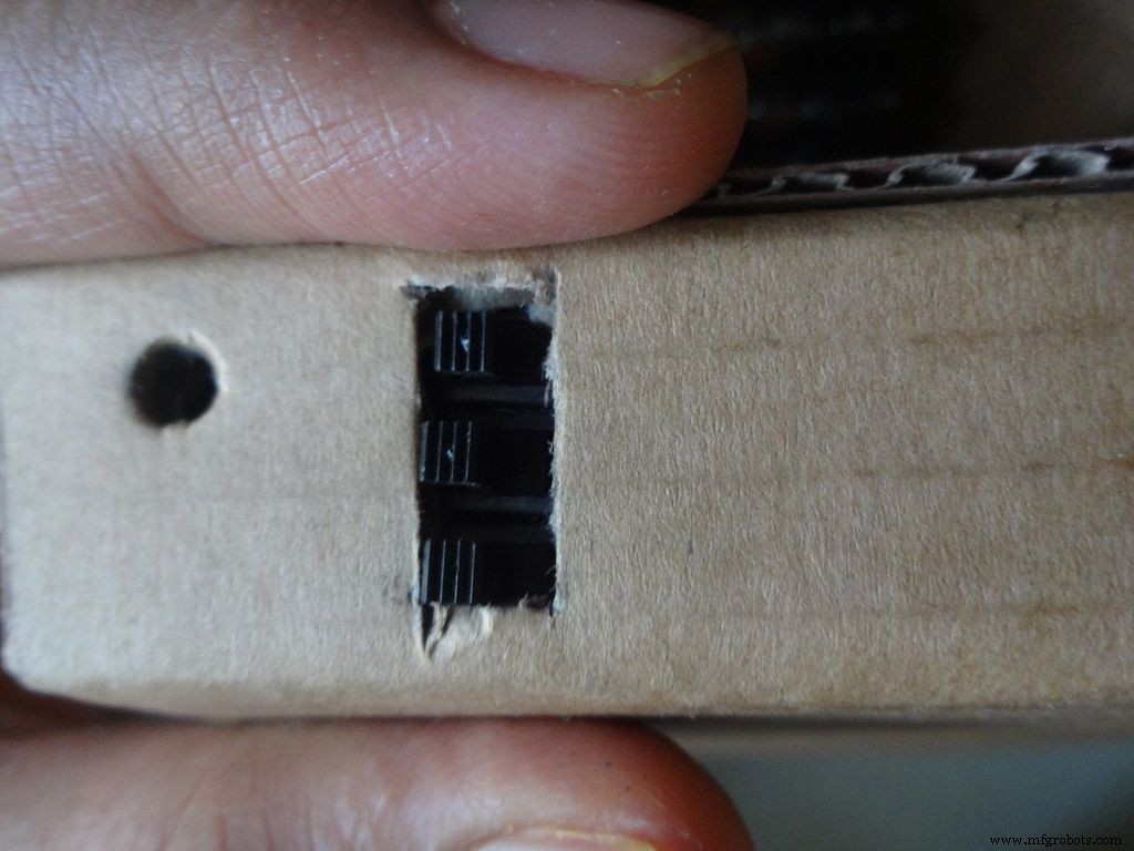
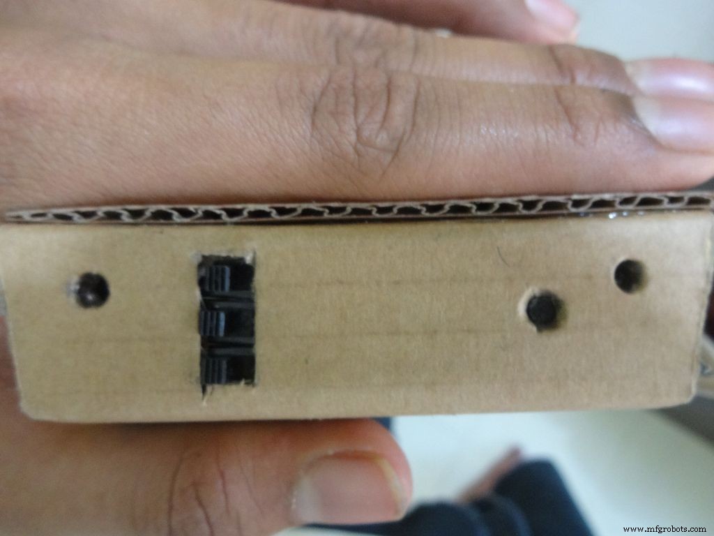

Ambil 3 buah saklar geser dengan kabel yang sudah kita solder tadi, ukur kira-kira dimensi persegi panjang yang dibutuhkan. Mark it on the left side of the box(left from the outside). Cut it with a cutter, sand it a bit on the inside to remove any material sticking out.
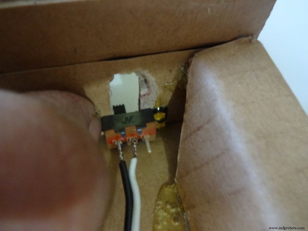
Keep the first switch in position and while holding it add glue on one side. Let it cool. Repeat with the other two as well, and then add glue on the remaining sides. Note:The wired pins of the switches should be on the same side.
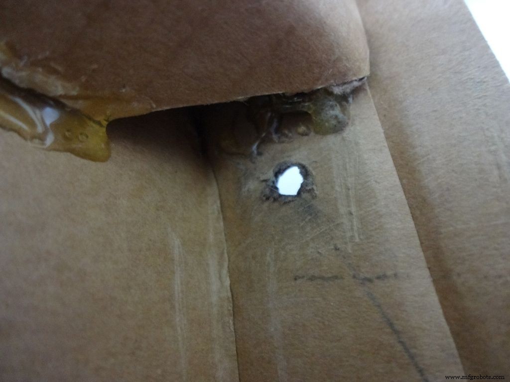
Make another hole on the other side for the reset pushbutton. Hold the button in place and add glue. Fold the lower flap inwards and stick it.
Step 11:Making the case - Top half or cover
Sand the edges and stick the side flaps inwards(just like the base) for the top half
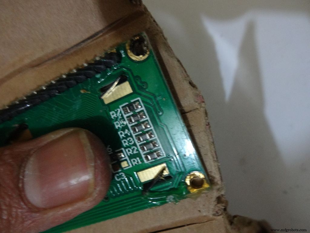
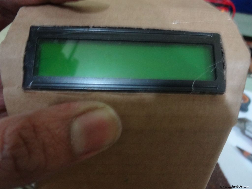
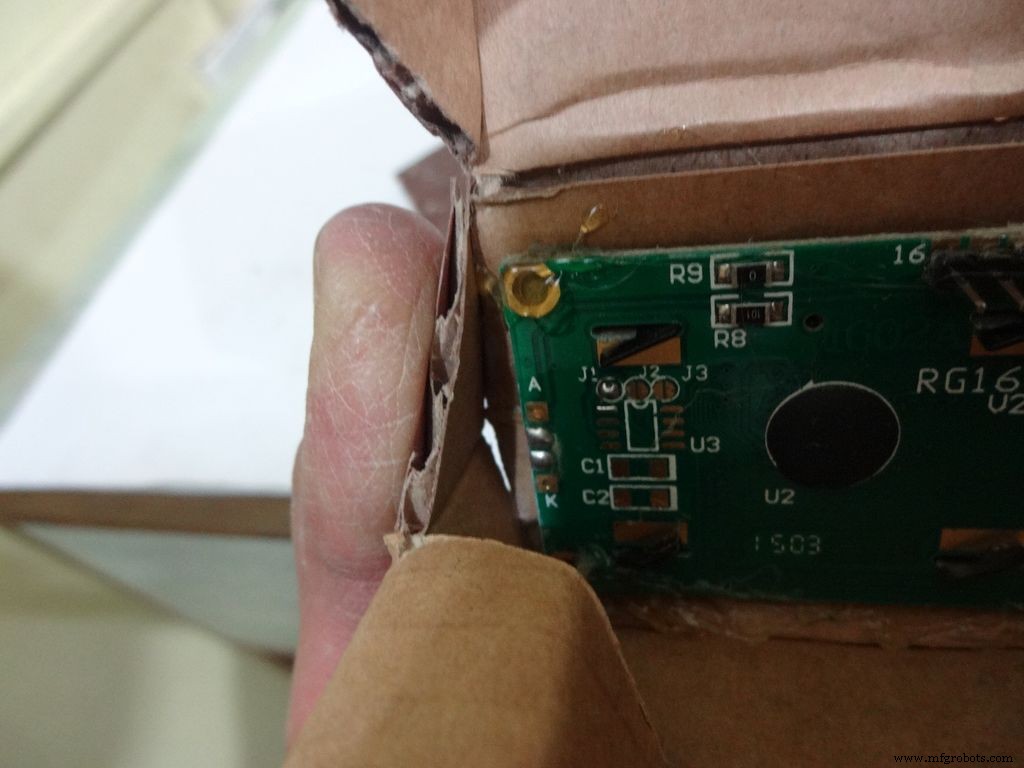
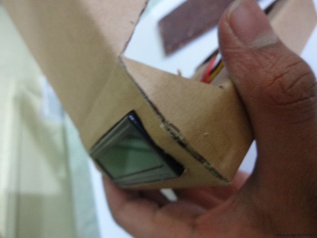
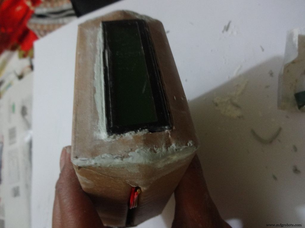
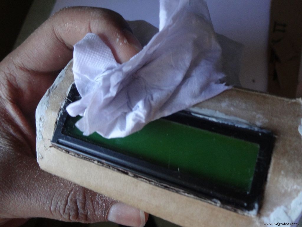
Step 12:Making the case - Adding the LCD
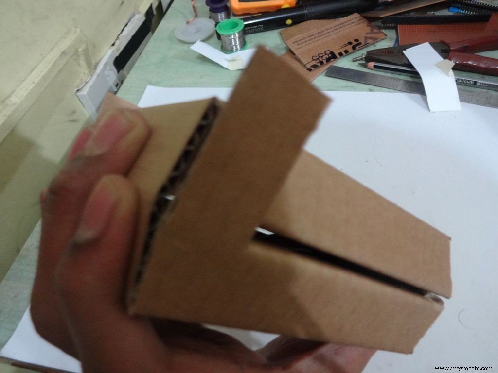
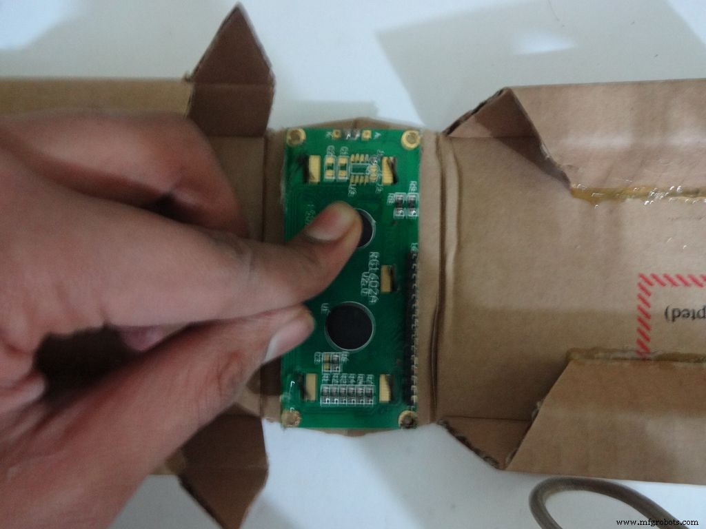
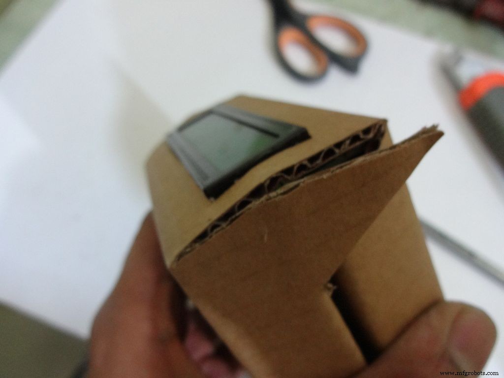
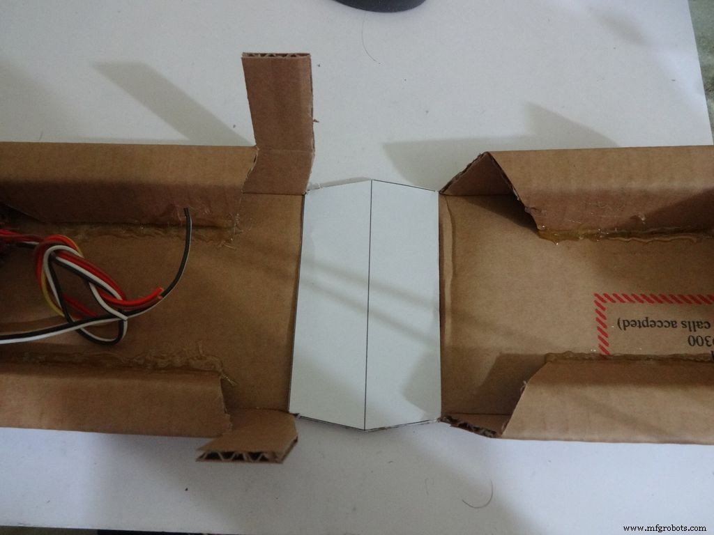
Crease the middle line. (Didn't do it earlier as it is delicate and gets loose soon).
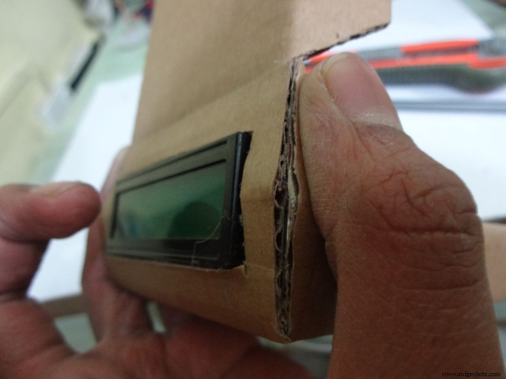
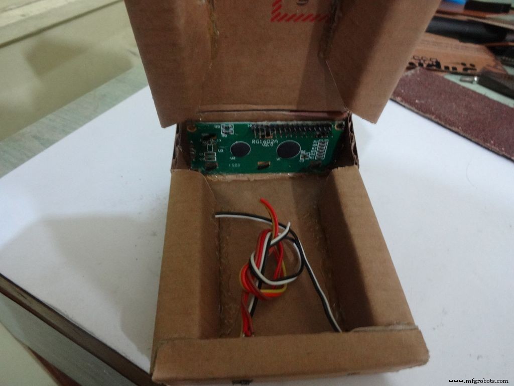
Fold the cover over to the base and check whether everything looks alright, sufficient spacing should be left for the IC pins. (See photo)
Cut the covering flaps as shown in the images.
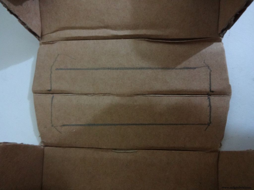
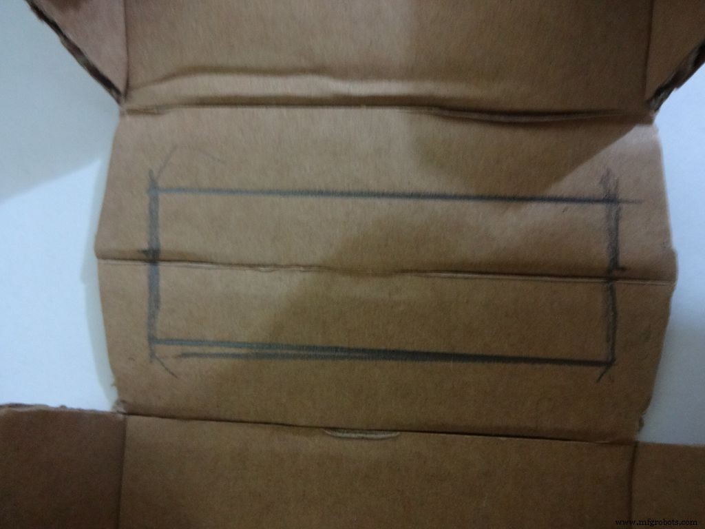
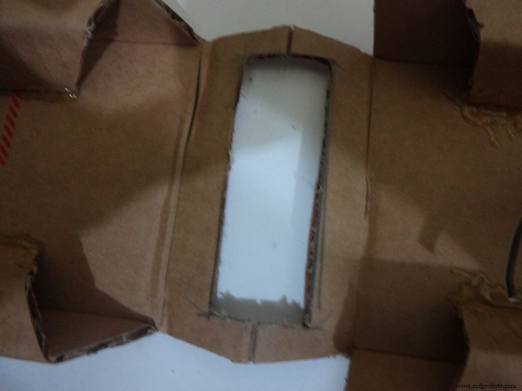
Keep the LCD at the center of the LCD Area, mark it with a pencil. Using a ruler, make the rectangle properly and cut it carefully using a cutter. Fold the LCD window and apply glue to the hinges to keep them at their correct position. Insert the LCD and make any modifications if required.
Finally, apply glue to the four corners(don't put excess) of the LCD and place it in position.
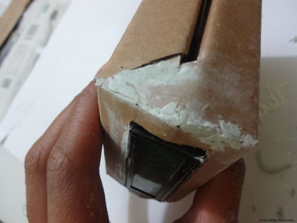
Step 13:Making the case - Final flaps
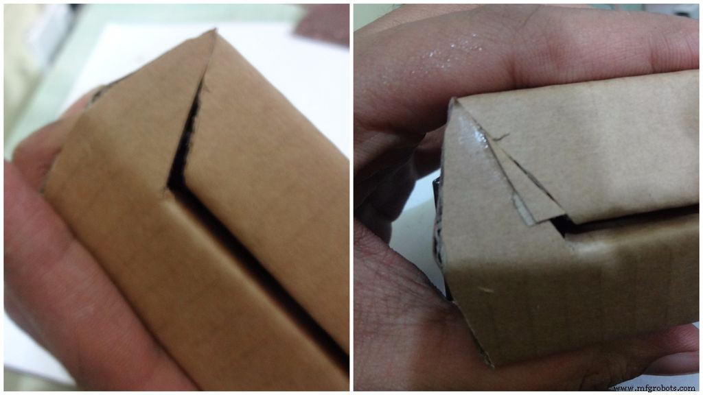
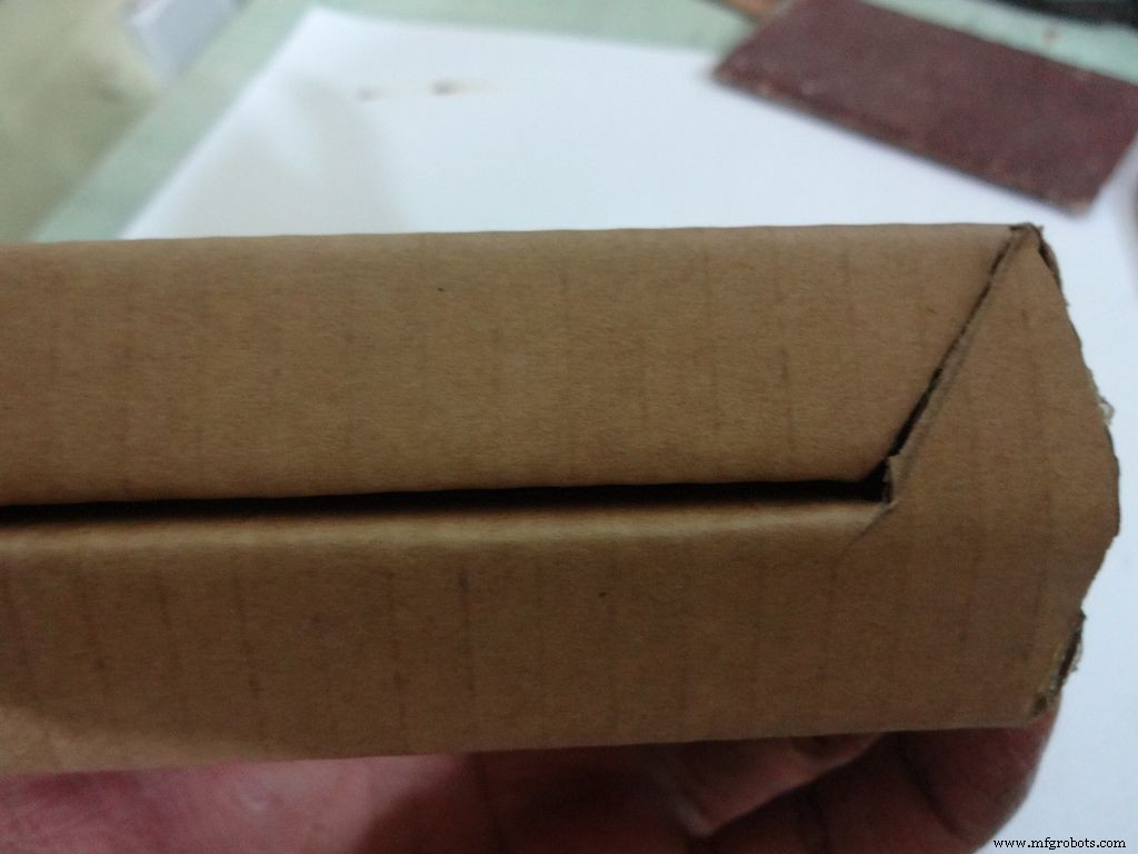
Sand, trim and close the tringular flap.
Make a small piece as shown and stick it to the cover. Make two holes, widen them with a pencil for inserting the bolt and locking the cover to the base.
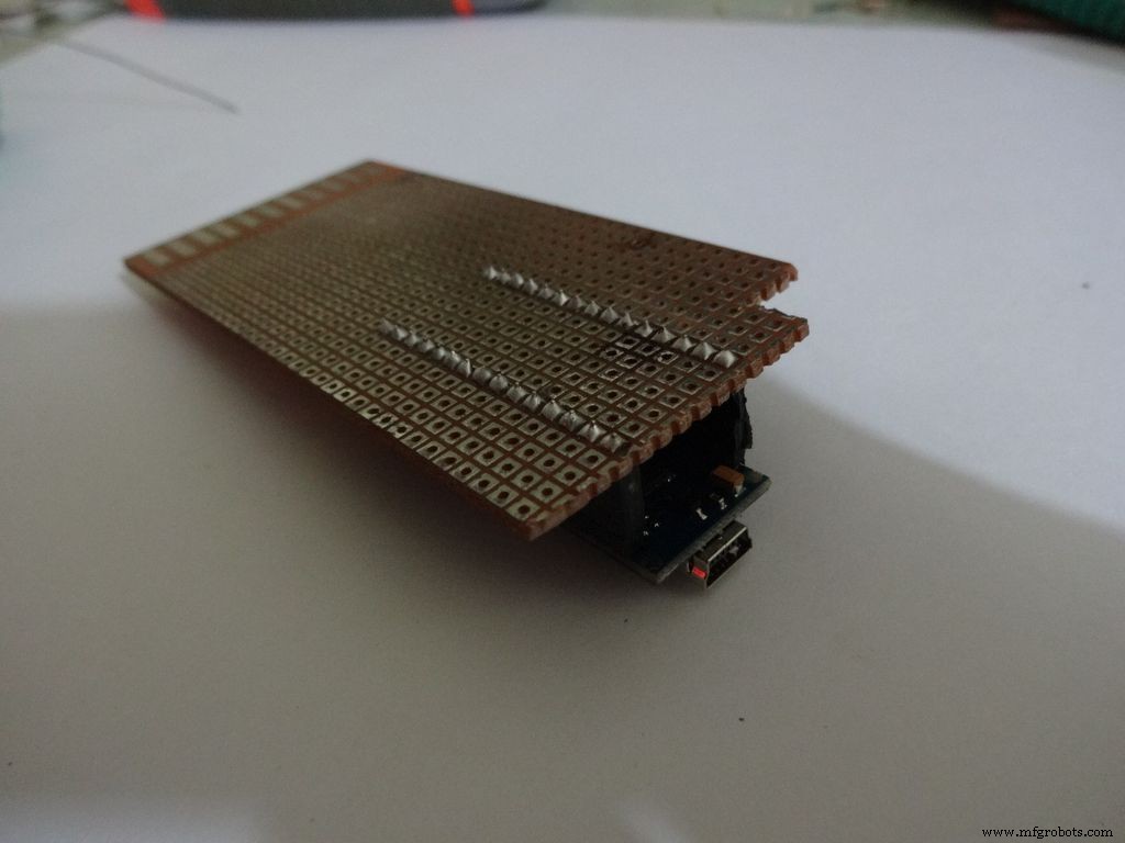
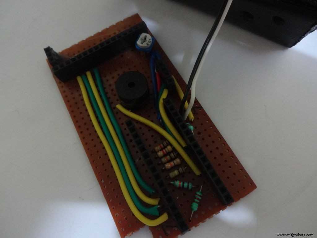
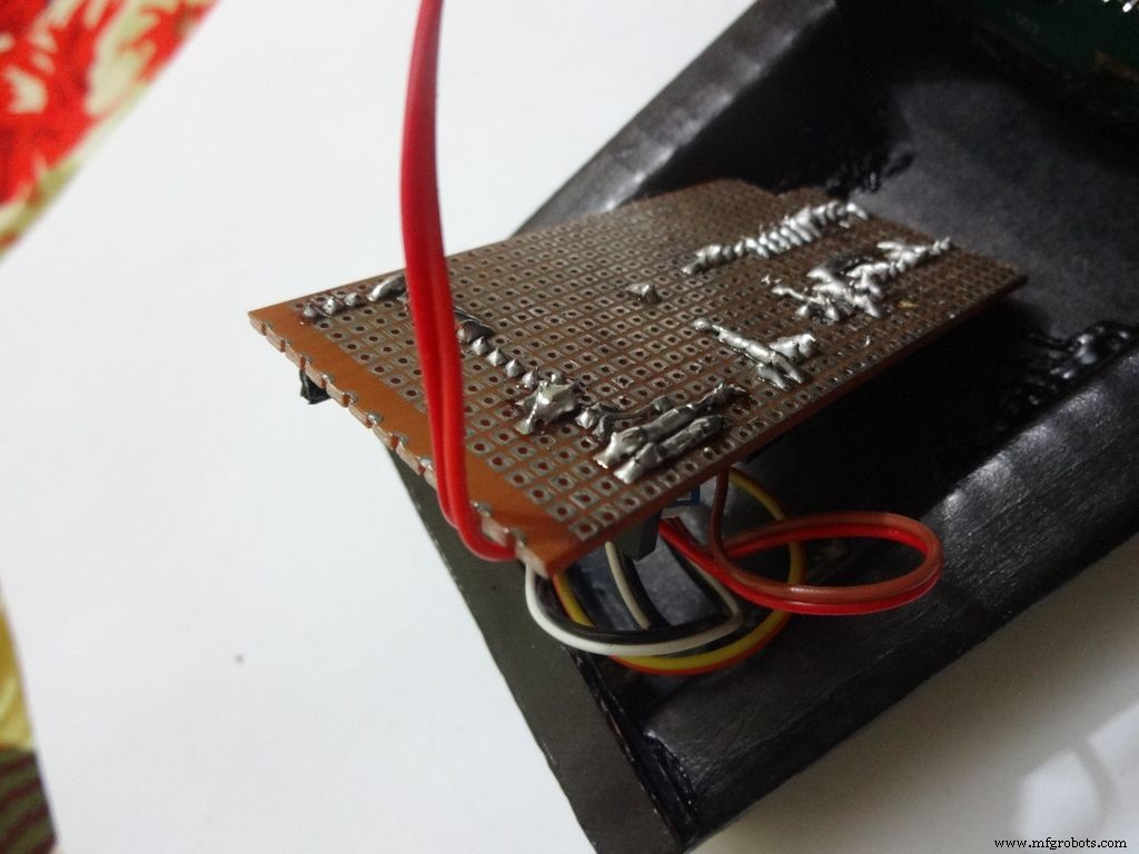
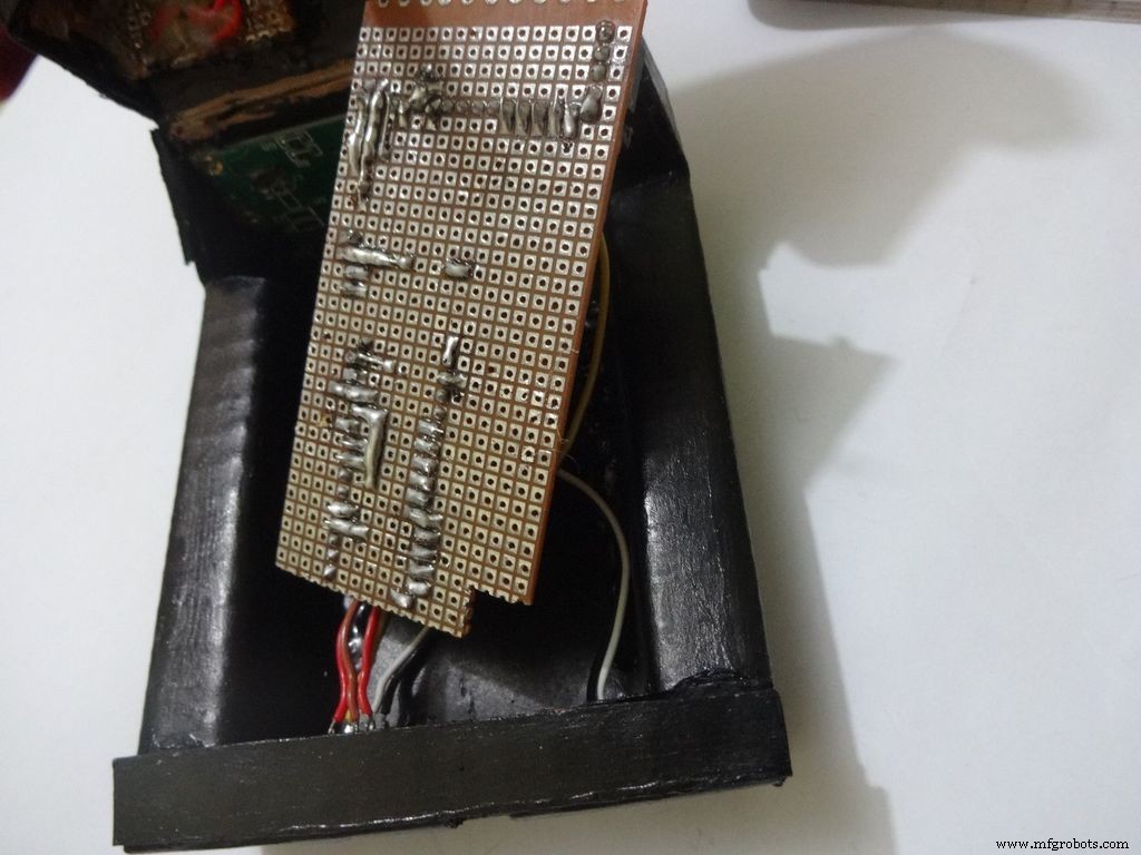
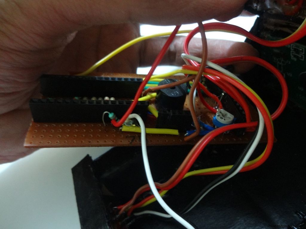
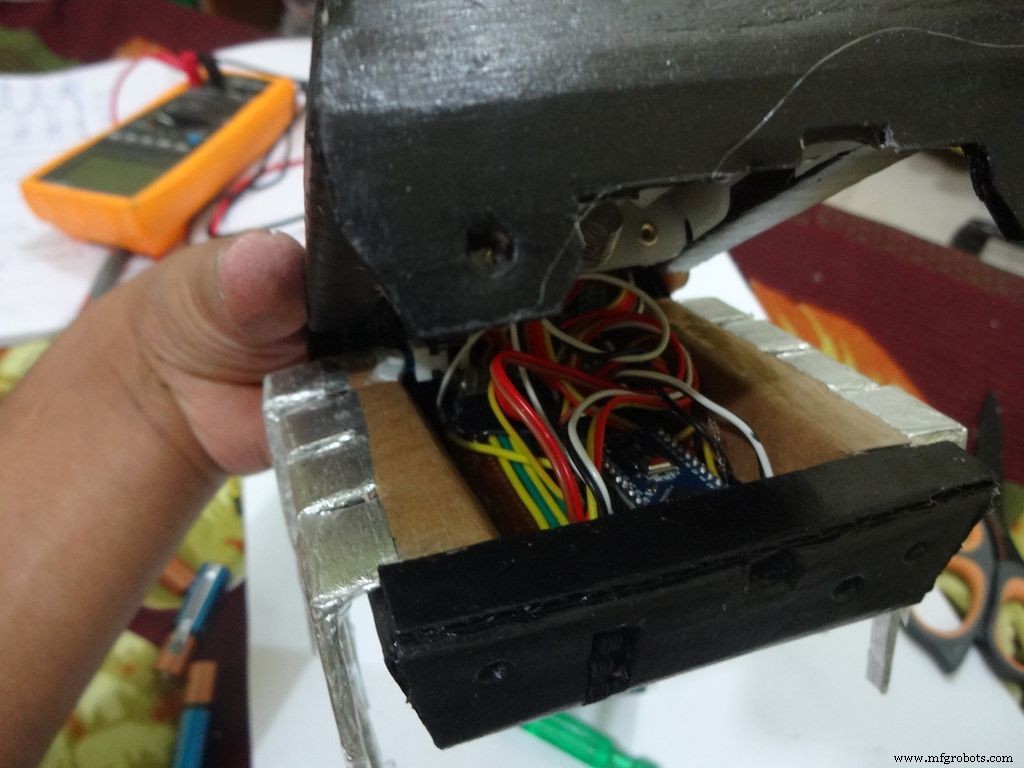
Step 14:The Circuit Board -- Making it fit

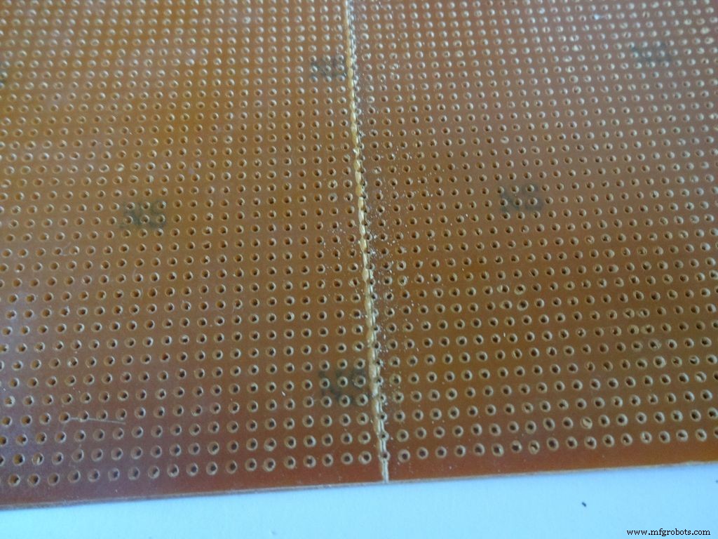
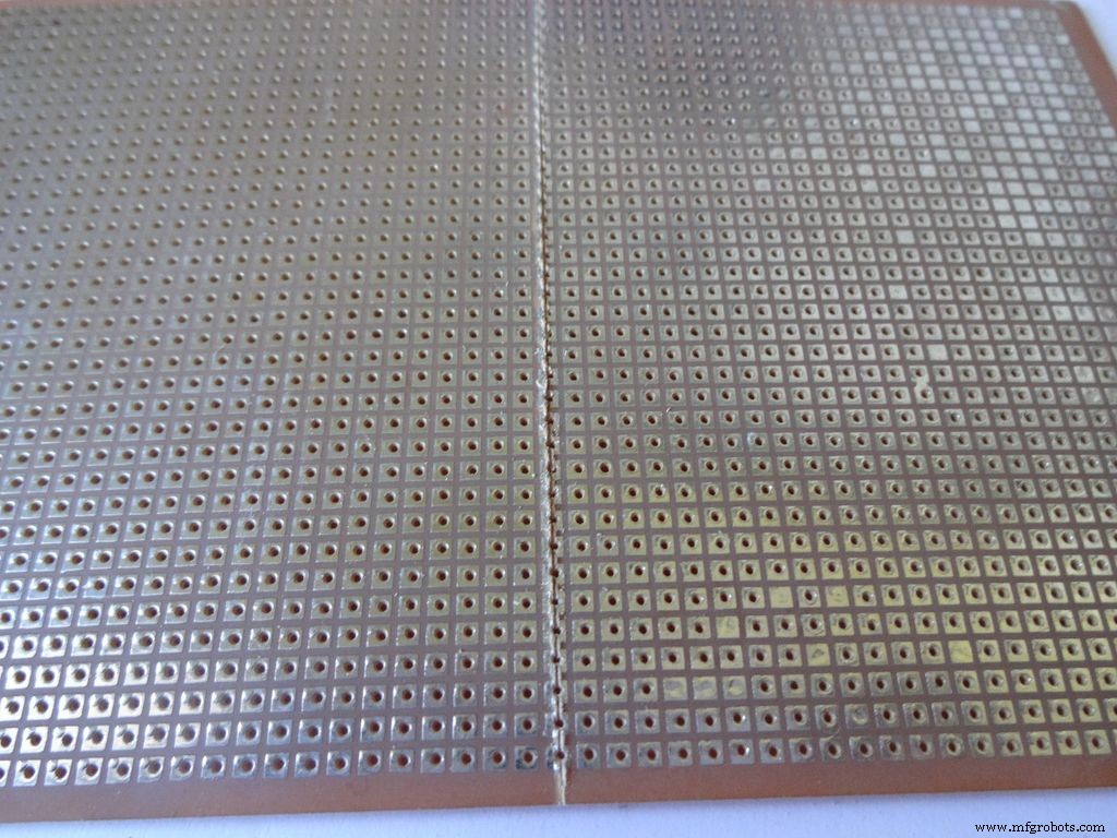
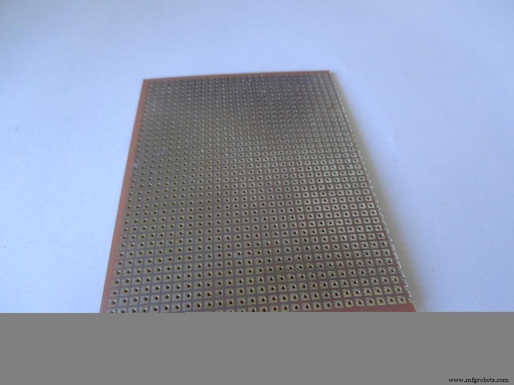
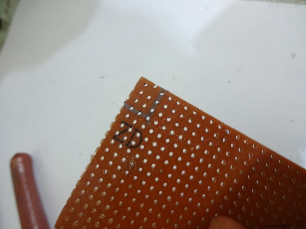
Cut the General purpose PCB to the right size such that it fits properly in the case. Mine is 2x4inches. To cut it, use the ruler and cutter and swipe it multiple times on both sides and it breaks off easily then.
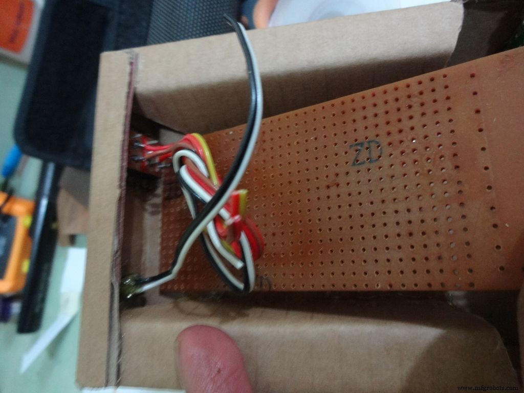
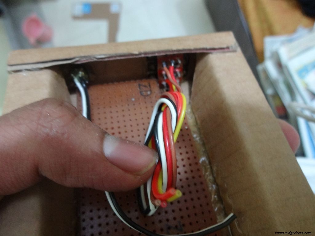
Place it inside. If the glue from the side flap lifts the PCB up, reheat the glue to flatten it or lessen the size of PCB a bit.
Cut a small part so that the 3 switches fit in and PCB goes entirely inside.
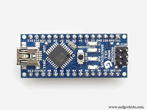
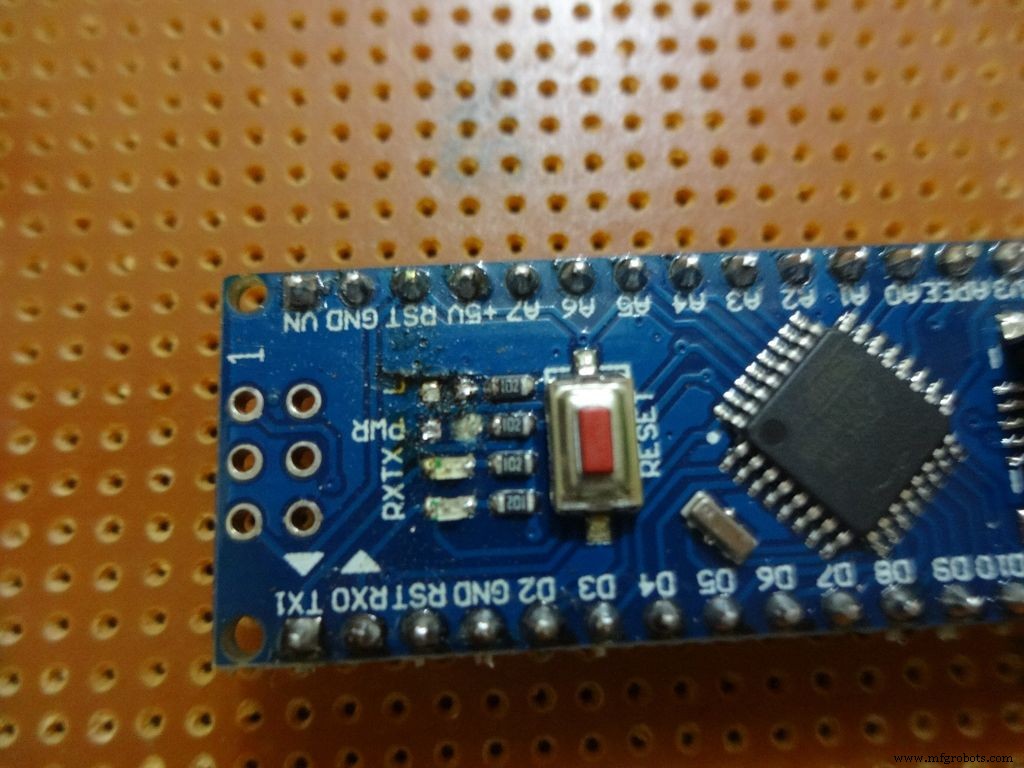
Step 15:The Circuit Board -- Arduino Nano

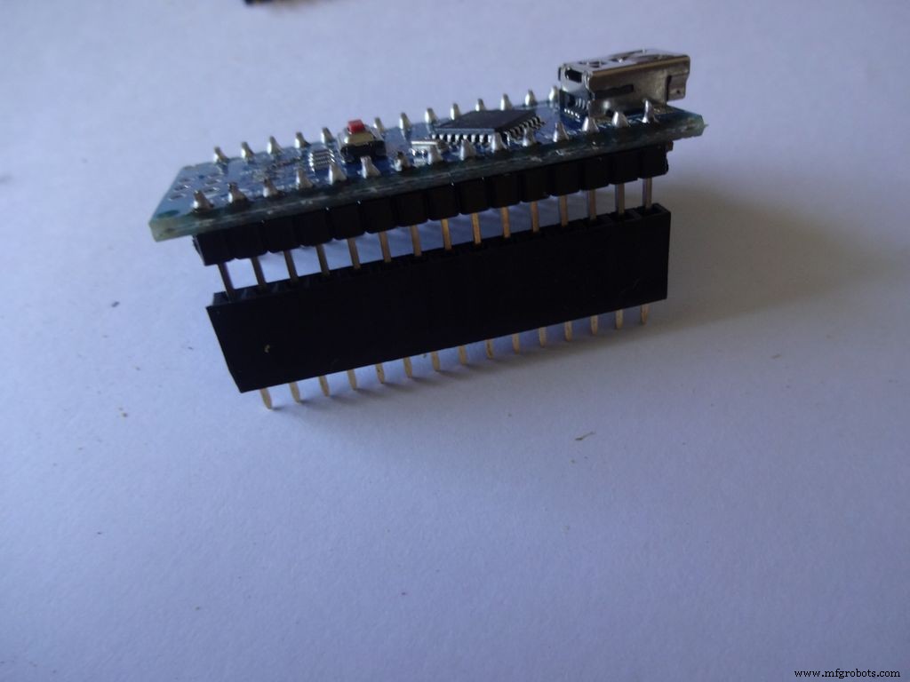
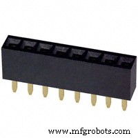
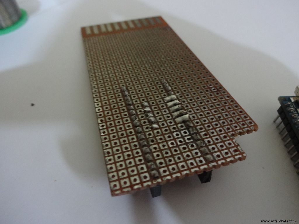
Cut female header pins of the right size for the Arduino.
Place it at the center edge of the PCB and solder all the pins.
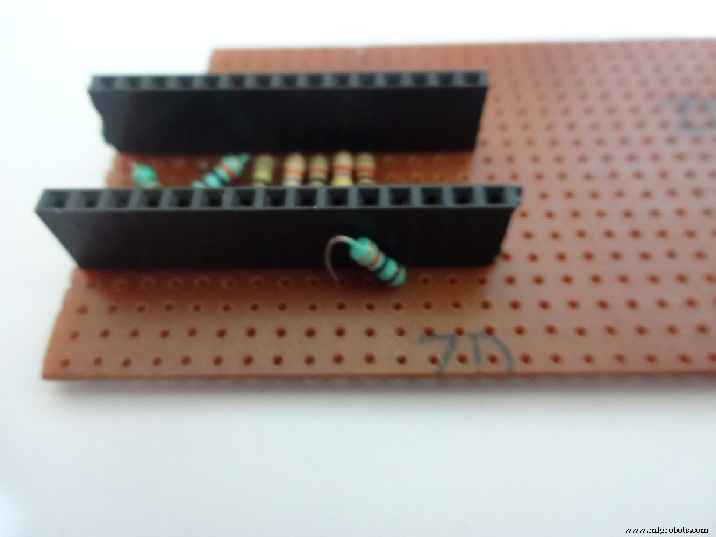
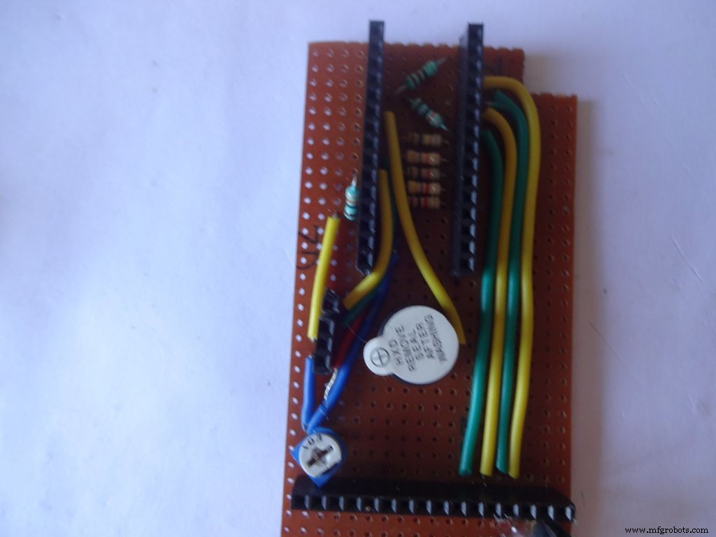
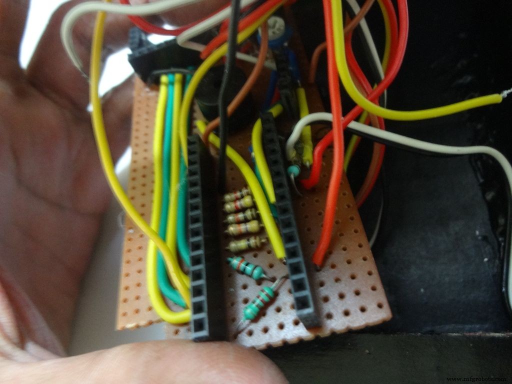
Step 16:The Circuit Board -- Ohmmeter
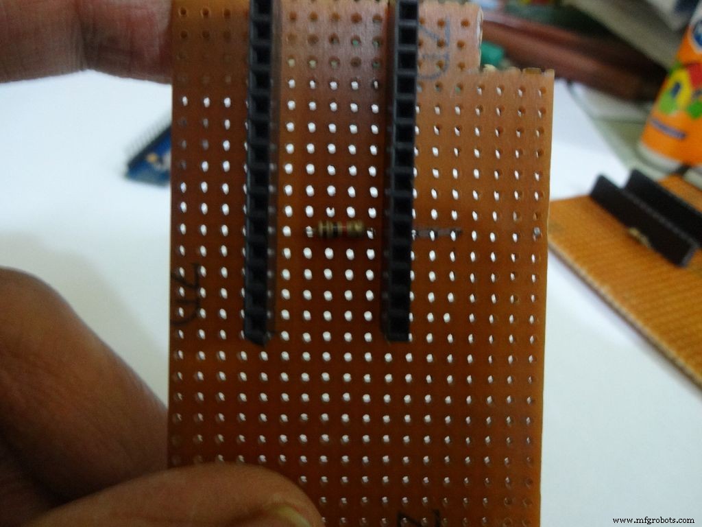
Before making any connections on the PCB please double check from the final Circuit Design.
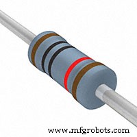
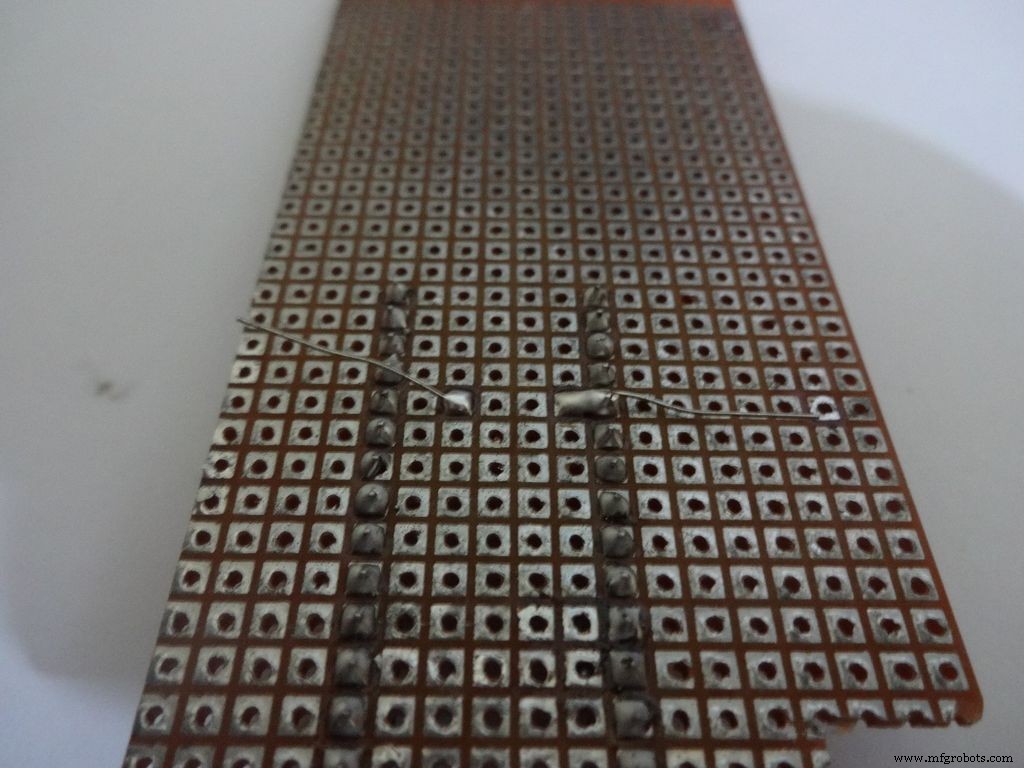
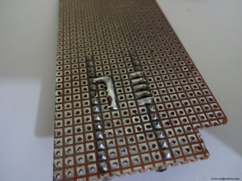
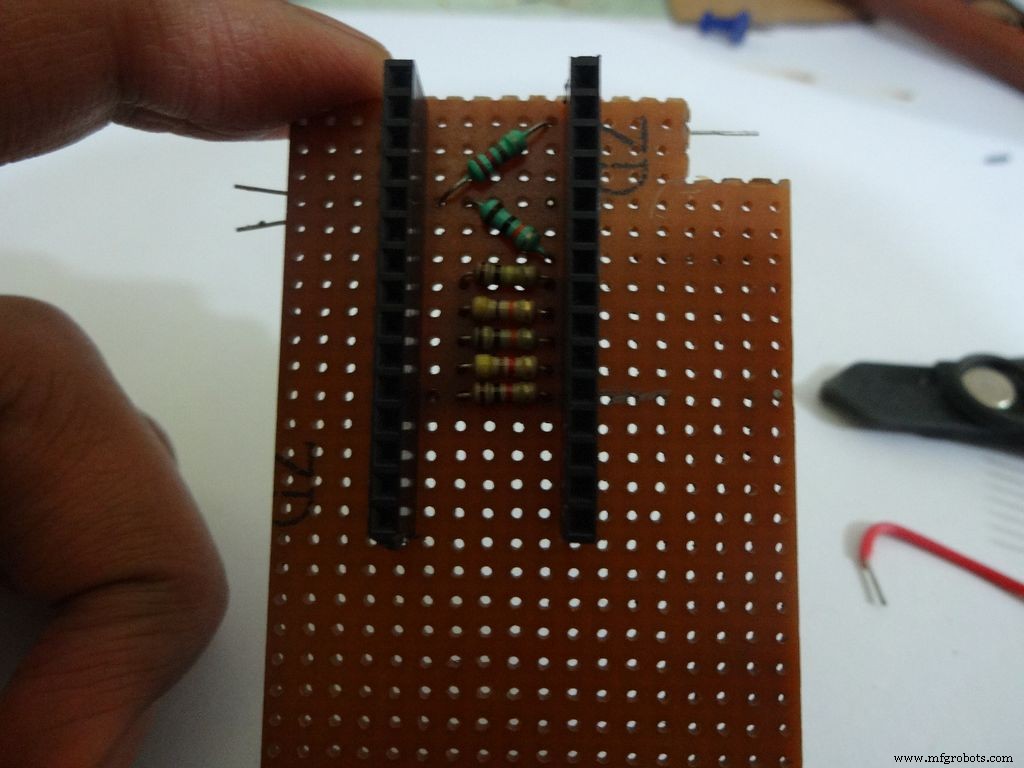
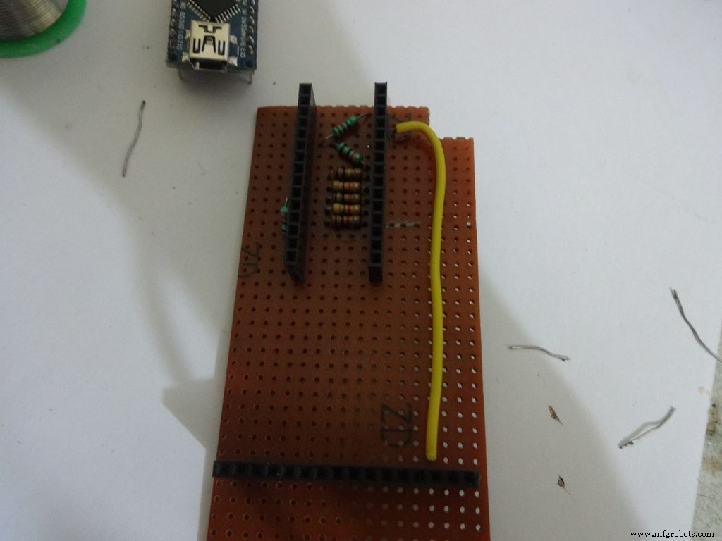
For the ohmmeter start by adding a 1k Ohm resistor to pin D2 of arduino. Place the arduino and carefully mark the pin. On the reverse side, bend as shown and solder it.
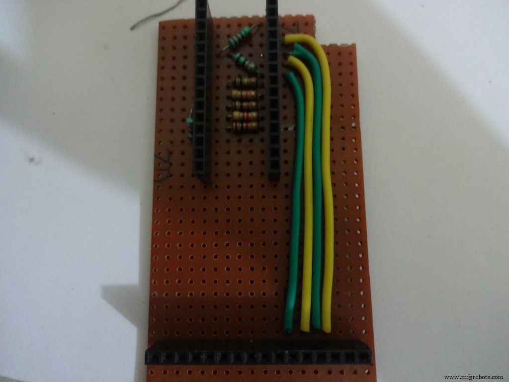
Do the same with the other 4 resistors, 4.7k, 10k, 47k and 100k Ohm.
Note:keeping all the tolerance bands(gold band) on one side is a good practice, eg UP and RIGHT.
Combine the second ends of resistors and solder it to A7 .
Step 17:The Circuit Board -- Capacitance Meter and Diode Test
Capacitance Meter:
Solder a 220 Ohm resistor from D12 to A0 . And a 10k Ohm resistor from A0 to D7 .
Note: D7 (digital pin) is also used for LCD data pin D4 .
Diode Test:
Solder the 10k Ohm pullup resistor from A6 to +5V .
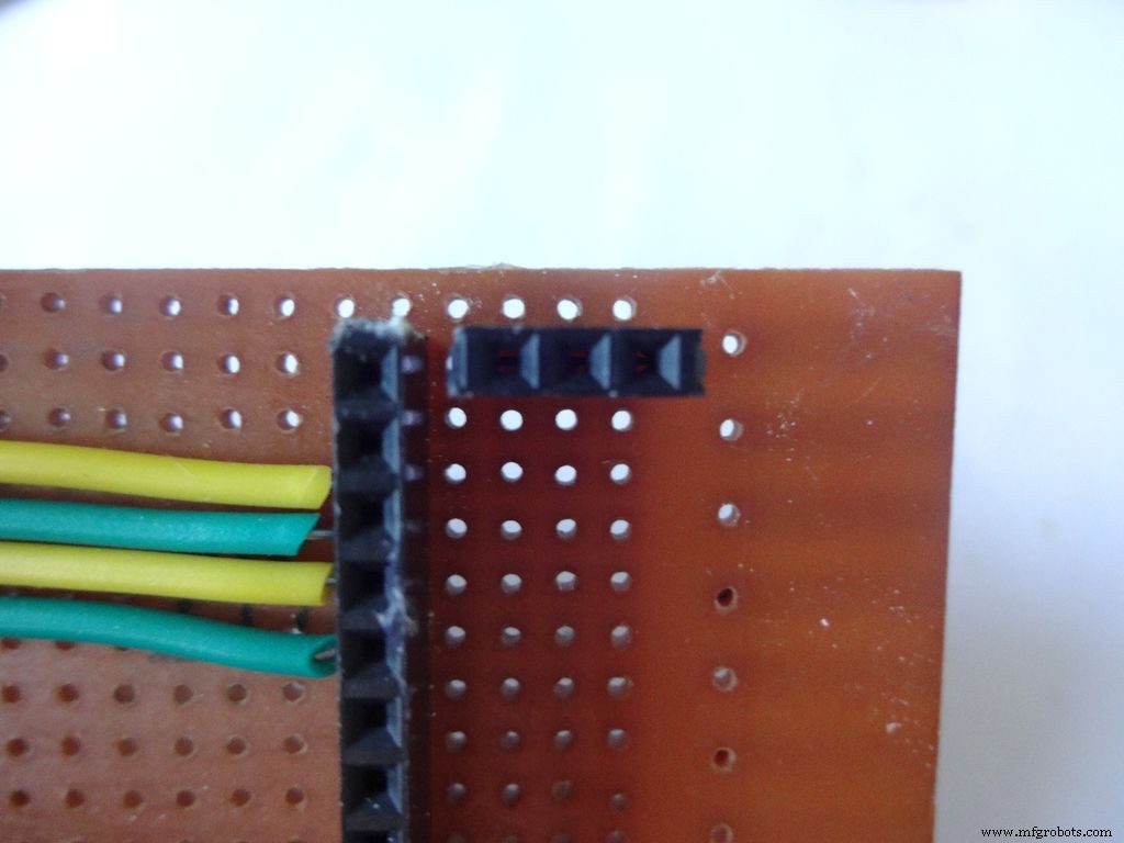
Step 18:Making connectors for LCD
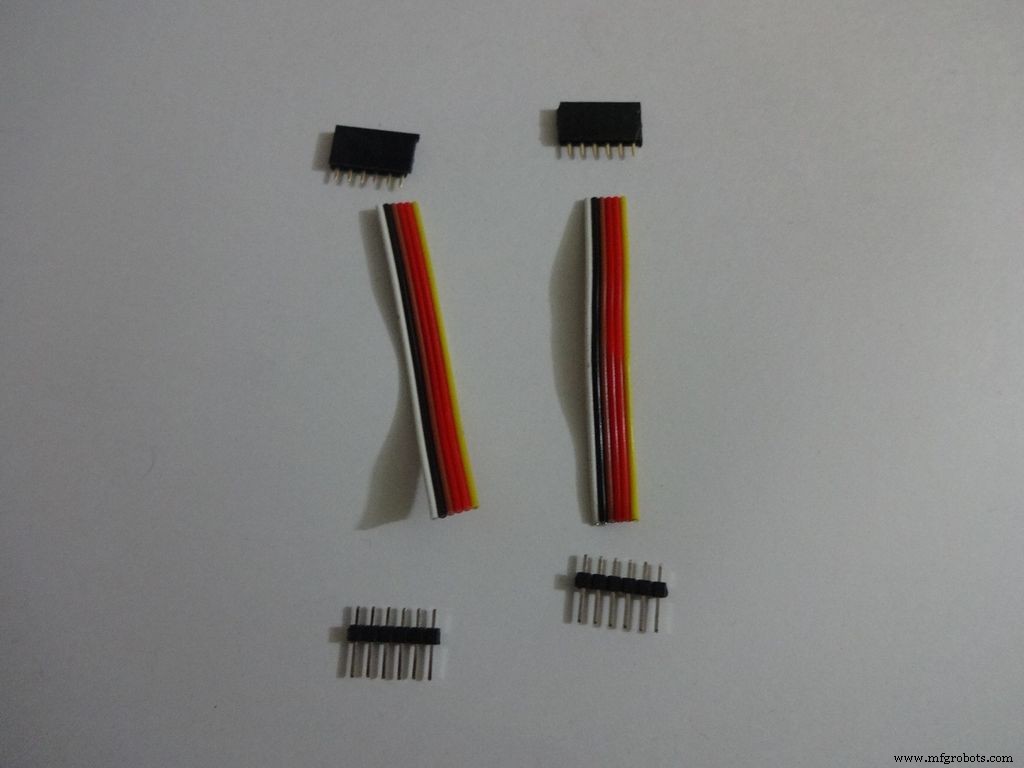
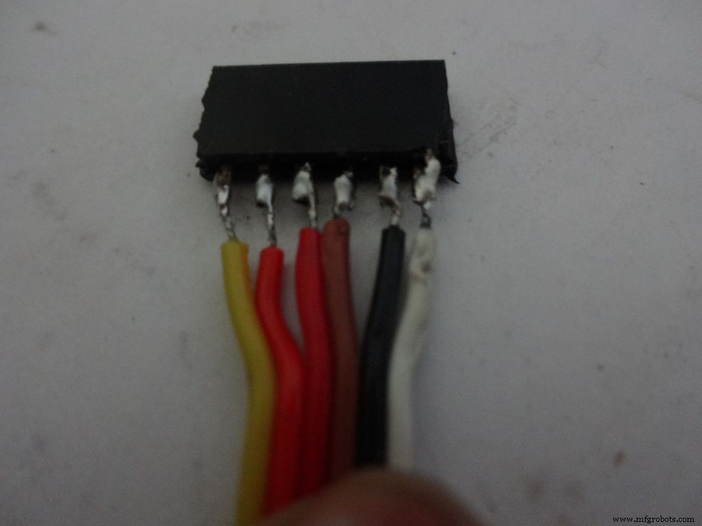
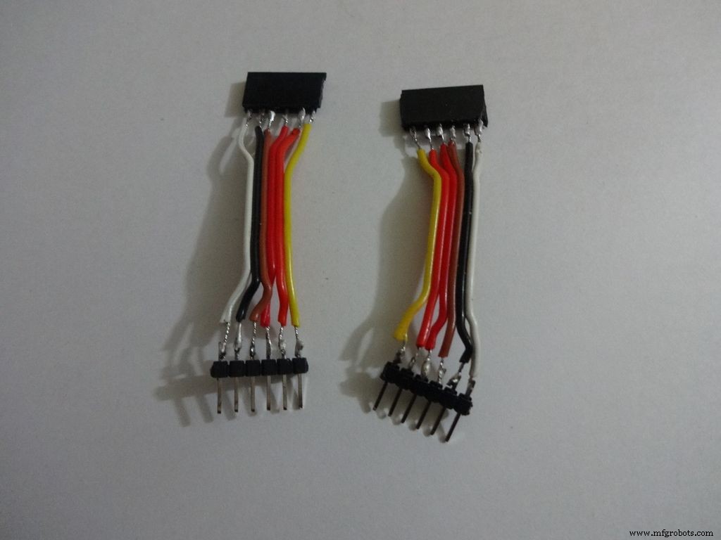
We just use the first 6 and last 6 pins on the LCD. Pins D0-D3 are unused. So we will be making connectors for only the used pins. It is recommended that you do the same because plugging/unplugging a 16pin connector becomes very tough once the build is complete.
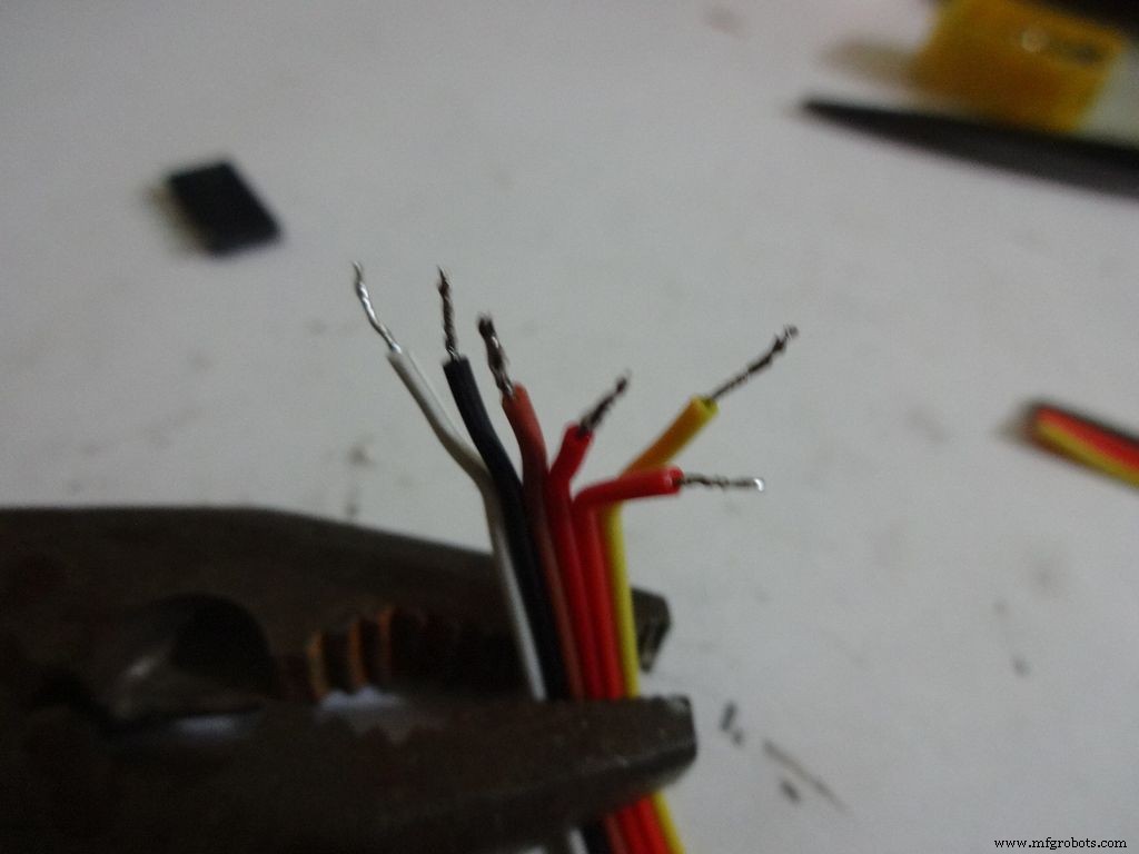
Cut 2x 6pin female and male header pins. Also take 6 wire ribbon cable, around 2-2.5 inches long.
Strip the insulation and tin the leads. Also tin the header pins. Join them one by one just like the slide switches.
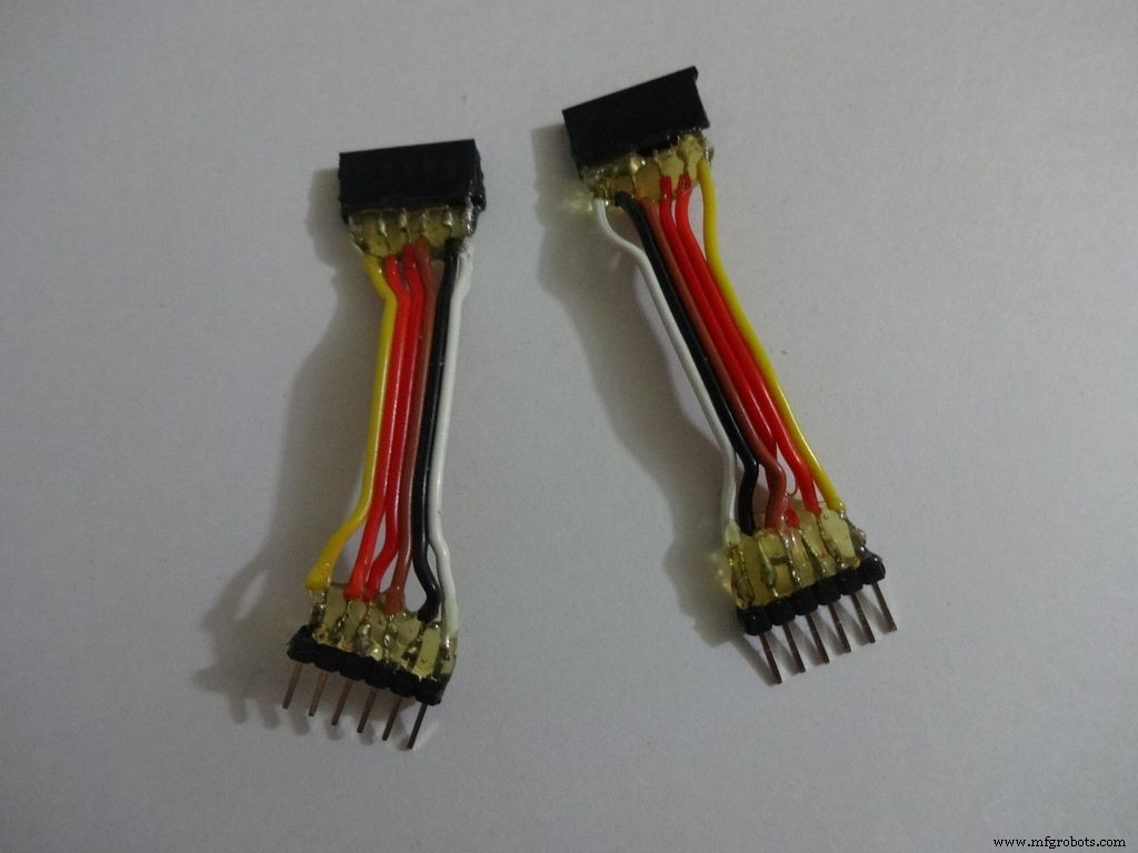
Apply hot glue to secure the wires.
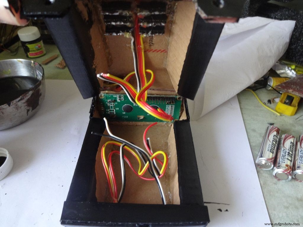
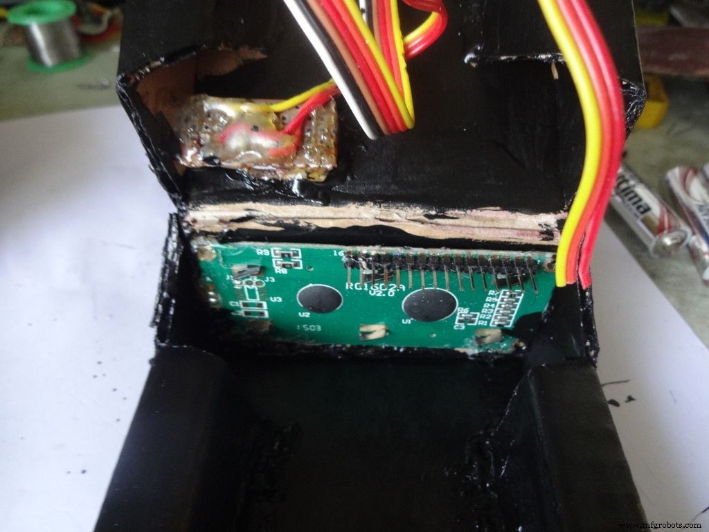
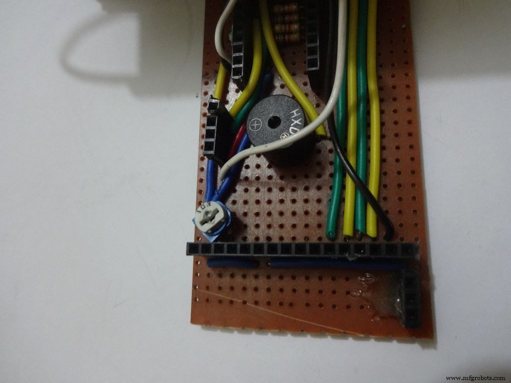
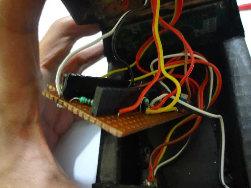
Step 19:The Circuit Board -- LCD connections
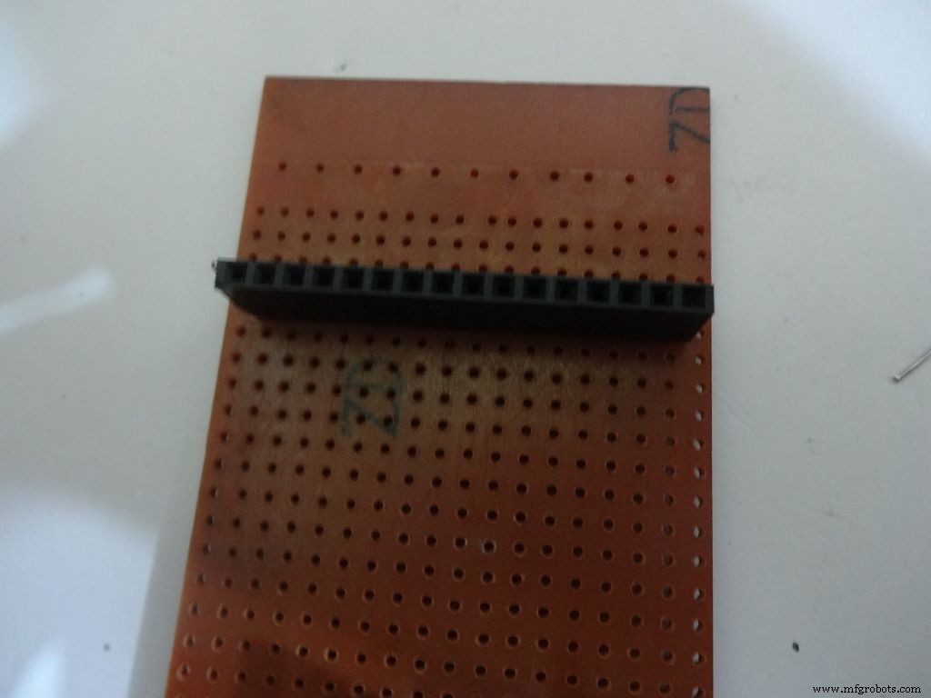
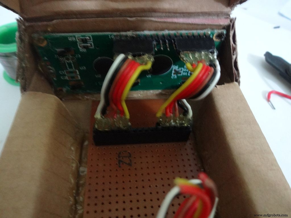

Place the PCB inside the case. Plug the connector to LCD and see where the female port should be on the PCB, solder it.
Make sure you leave 4-5 dot rows behind the LCD port. The Power switch will be added here later.
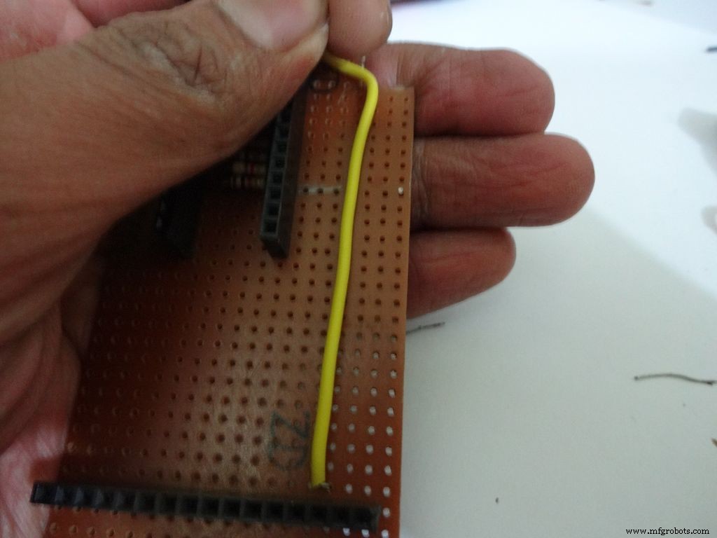
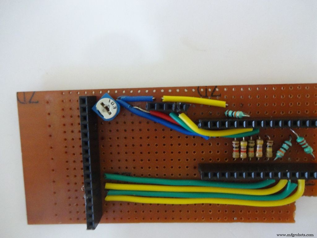
Measure the length of single stranded wire needed to connect data pins (D4 , D5 , D6 and D7 ) on the LCD to digital pins( D7 , D8 , D9 and D10 ) on the Arduino, respectively.
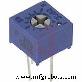
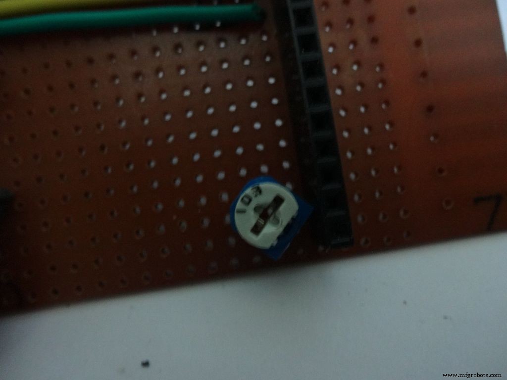
Add the 10k ohm potentiometer such that the side ends go to Vcc , GND and the middle pin to V0 .
Connect Vss(GND) on the LCD to GND , and Vdd to +5V . Also connect R/W to GND .
Arduino Pin
LCD
D7 D4 D8 D5 D9 D6 D10 D7 GND Vss(GND) +5V Vdd
Step 20:The Circuit Board -- RTC Module
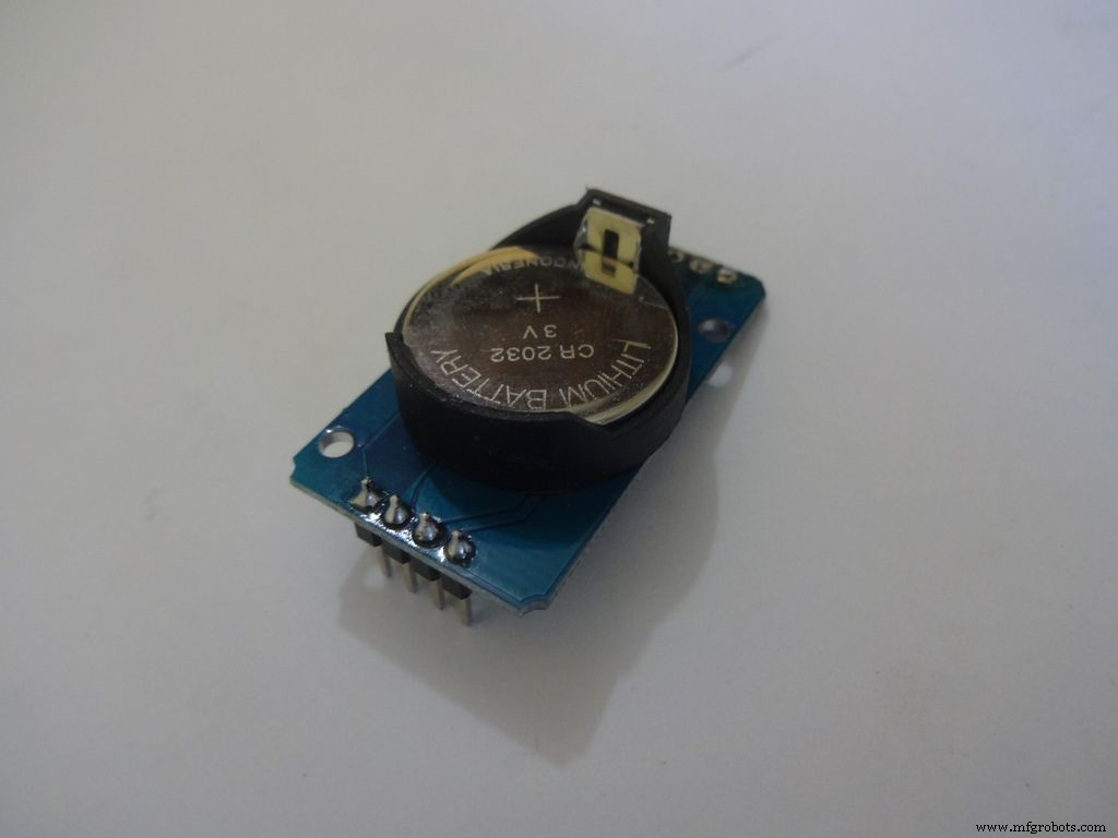
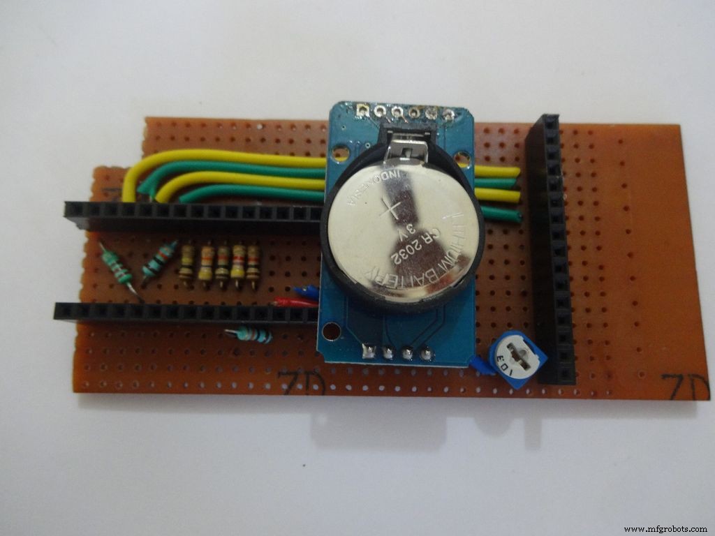
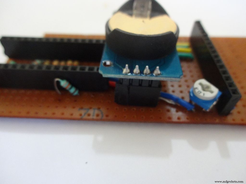
I desoldered the default 90 degree header pins on the module and added straight ones so that it fits flat on the PCB.
Solder 4pin female header pin and make connections to Vcc , GND , SDA to A4 and SCL to A5 .
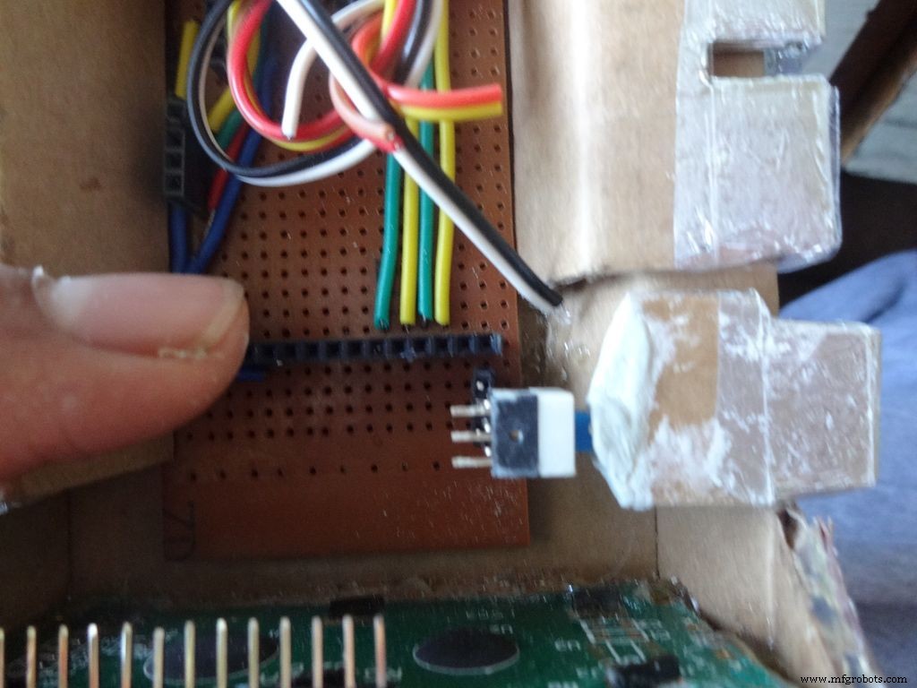
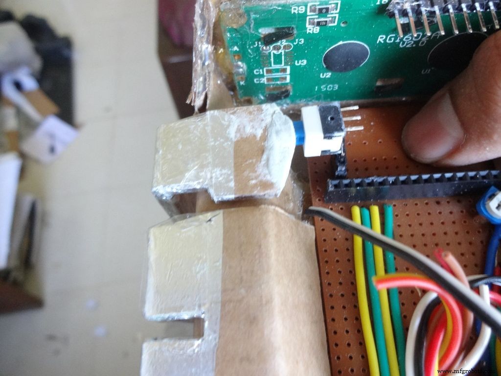
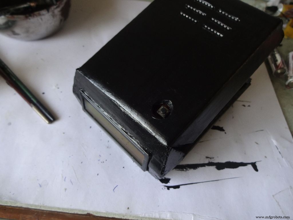
Step 21:Making the Case -- The mode button
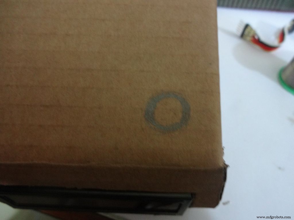
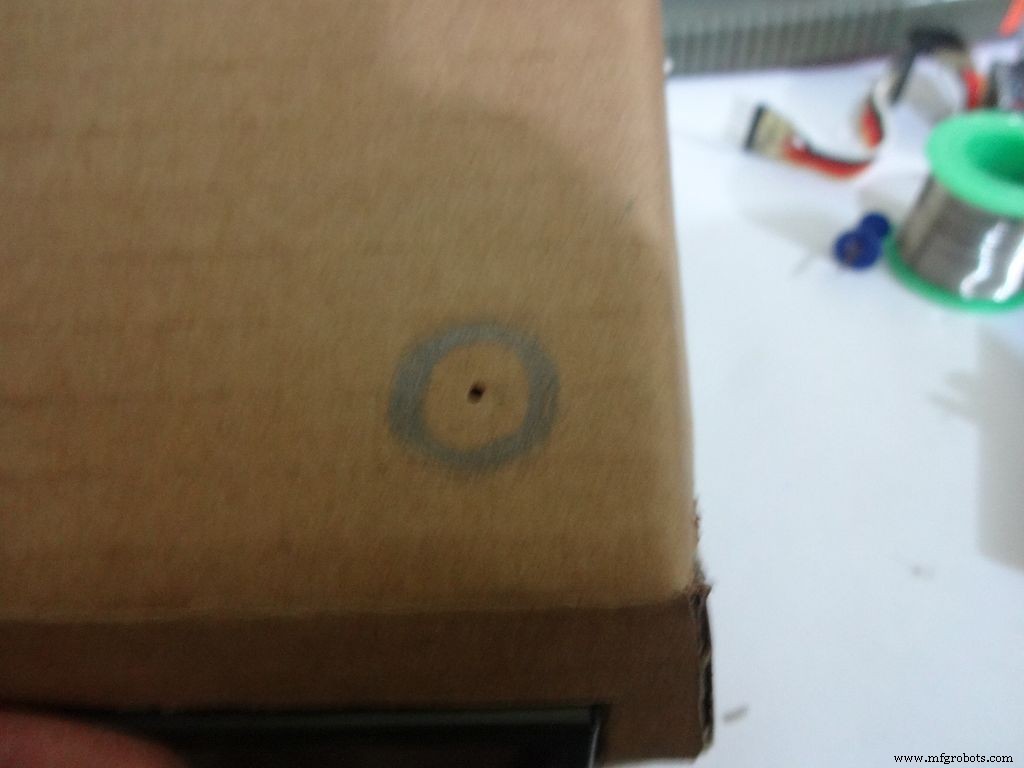
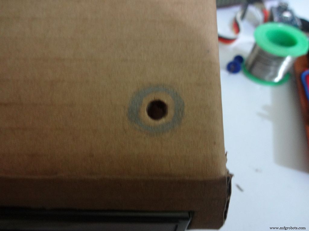
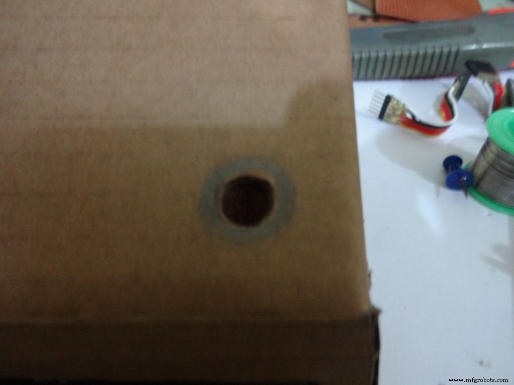
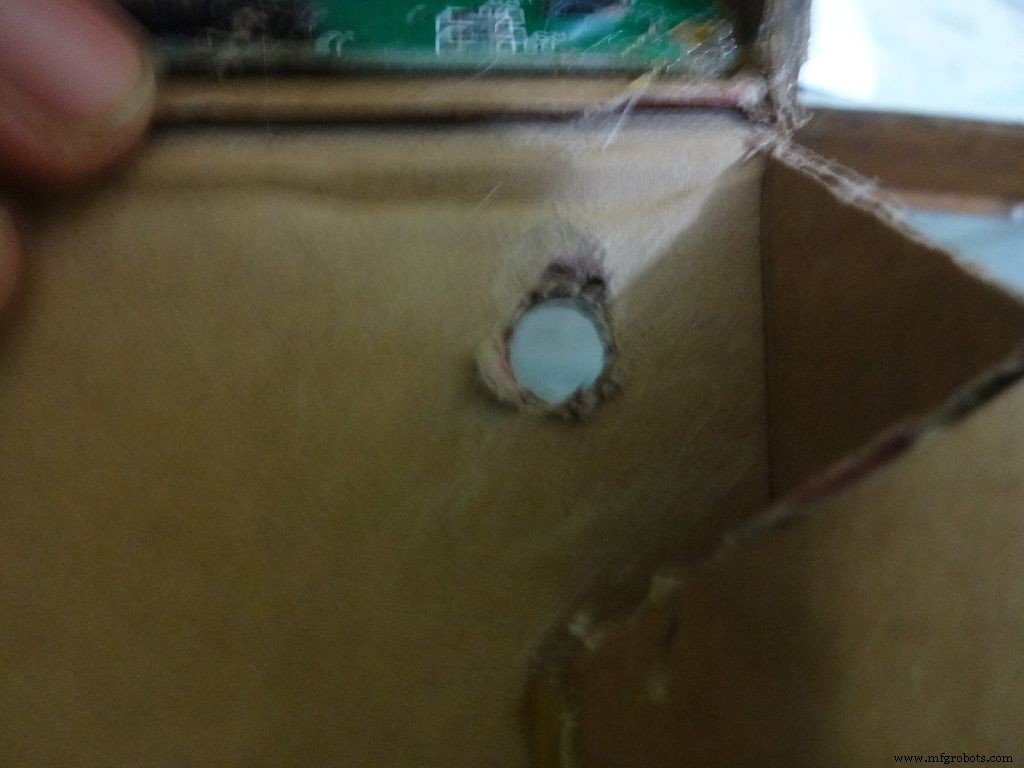
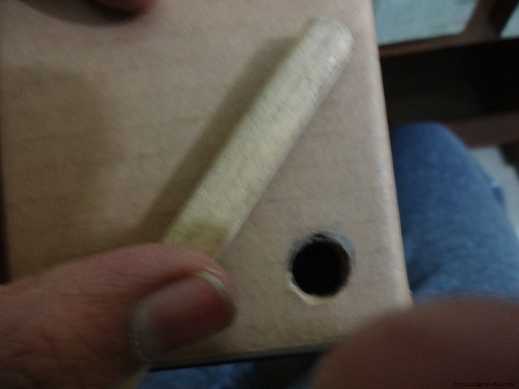
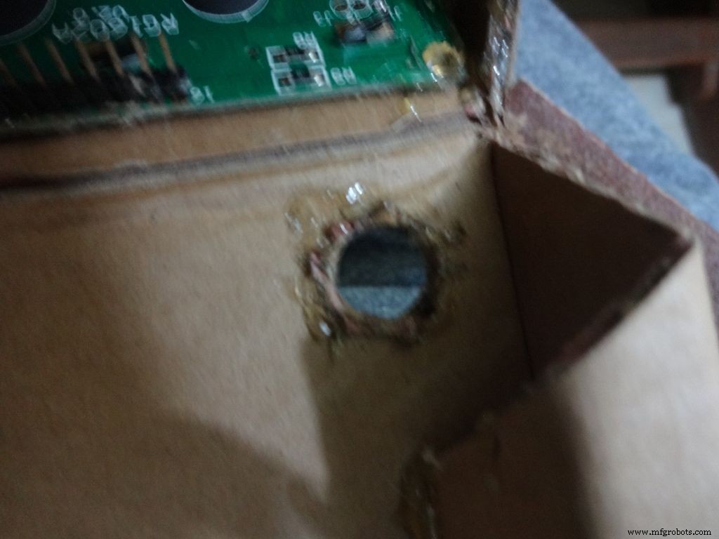


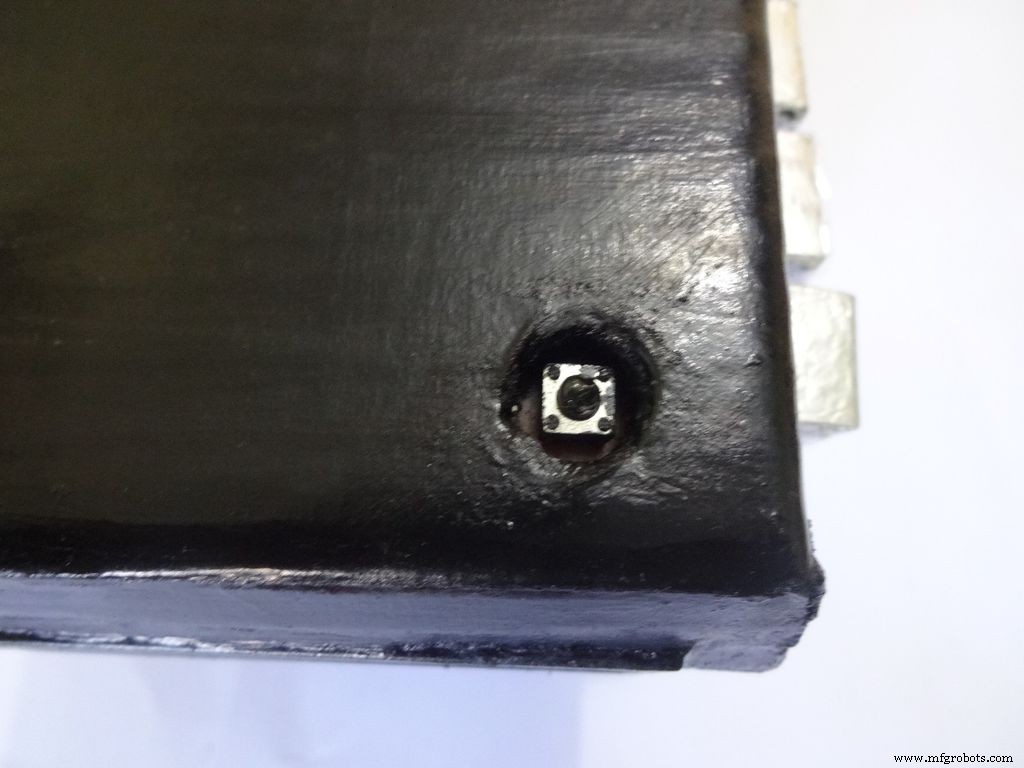
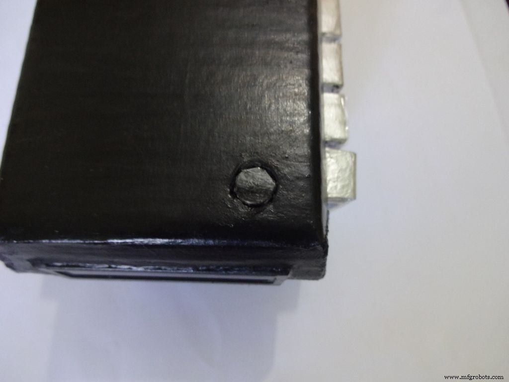
Mark a circle of about 1cm diameter at the pin1 corner of the IC case. mark the center with a pin, use a pencil to expand it. After that use some appropriate tool to increase the diameter to 1cm. Sand it on the inside and use hot glue to secure the hole.
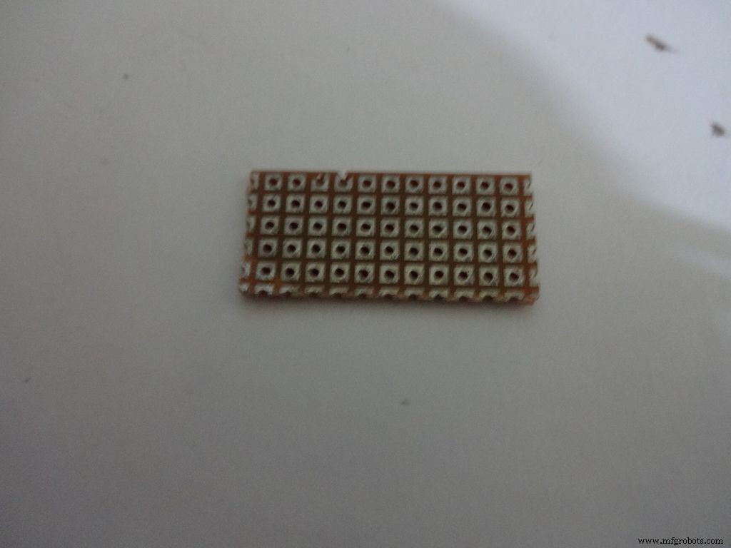
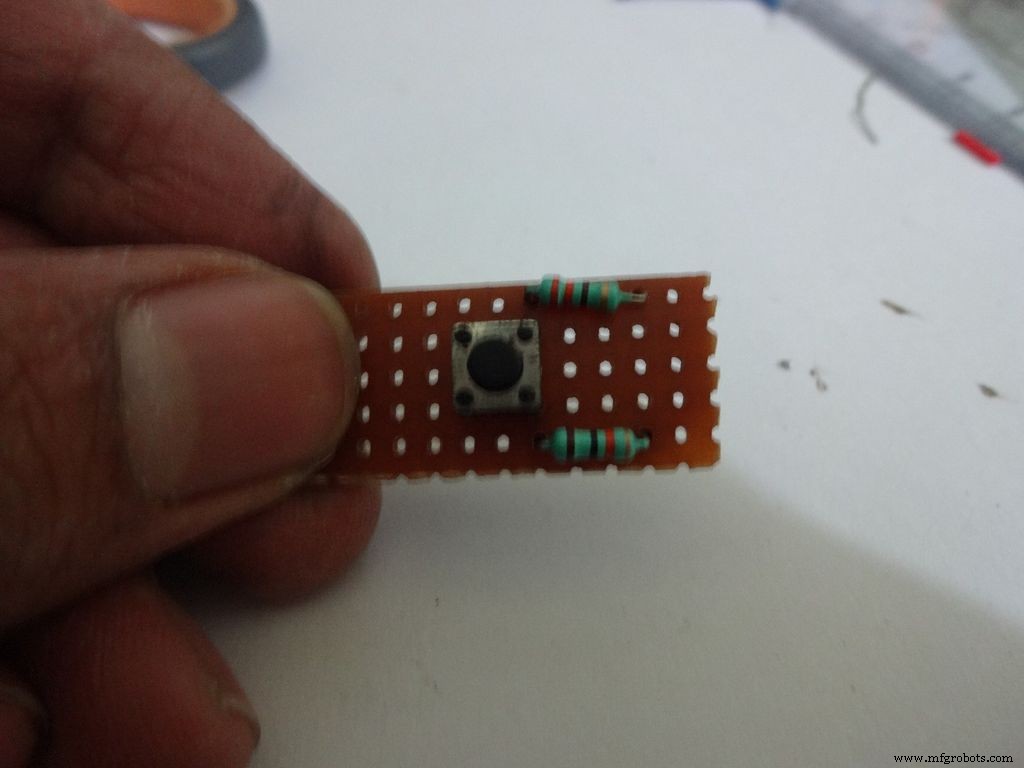
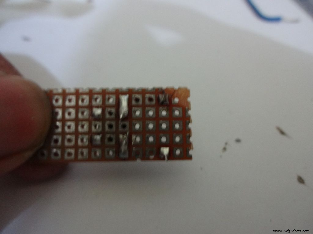
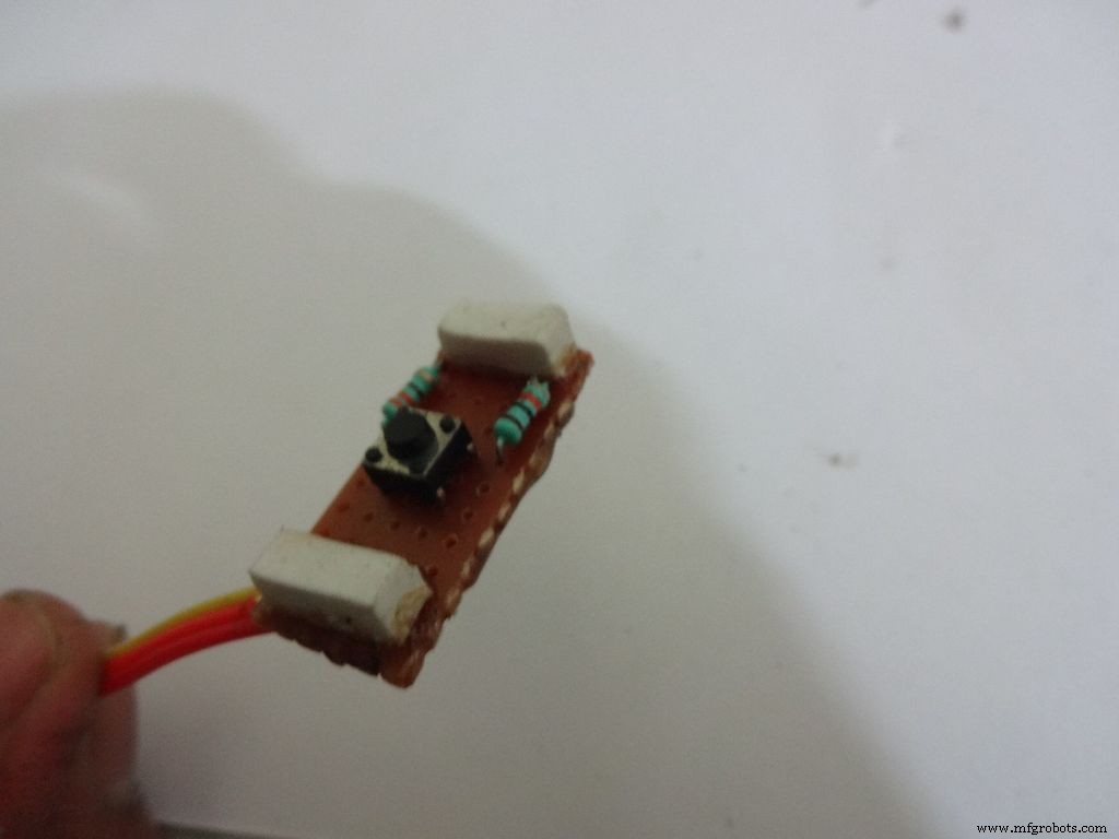
Cut a piece of General purpose PCB (10-11)dots x 5dots. Plug in and solder the pushbutton, 220 and 10k Ohm resistors as shown.
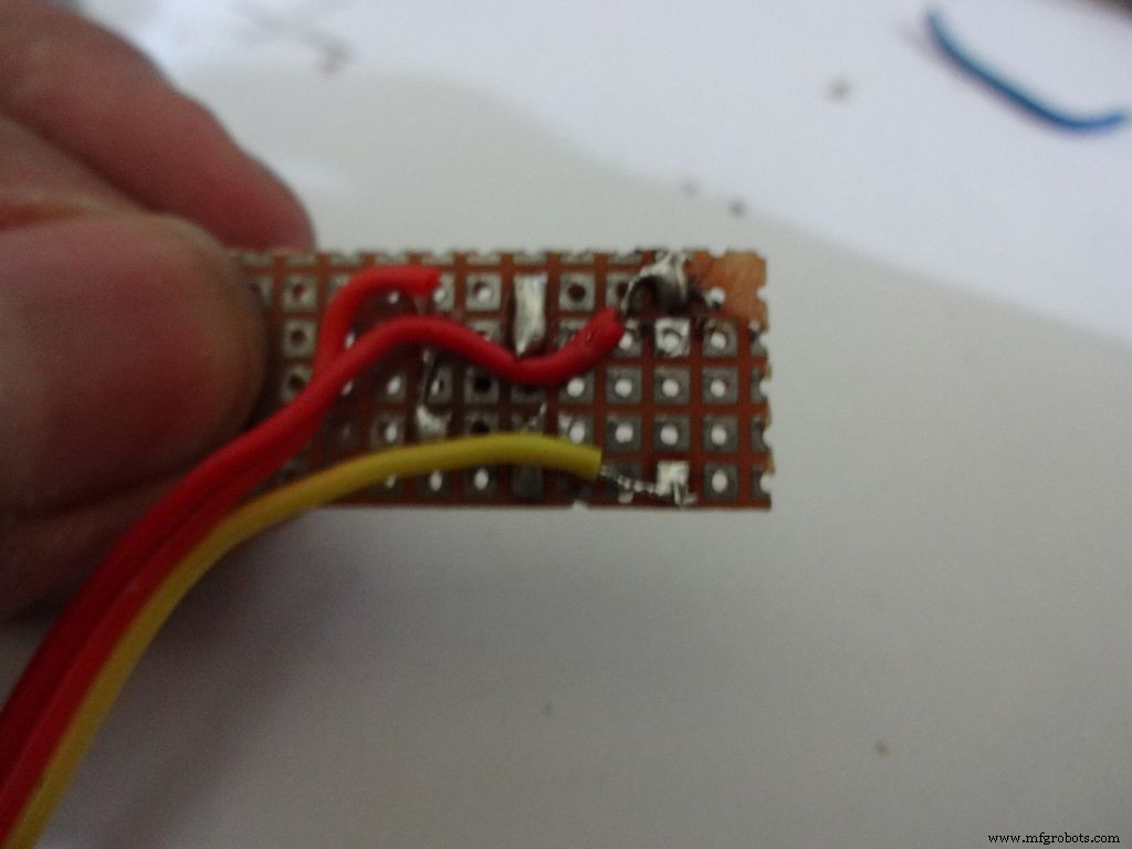
Take 3wire ribbon cable about 15cm long. Tin the ends and solder it as shown. Note down which colour wire goes to where, this will be helpful later on.
Cut 2 small pieces of eraser and place it on the ends on the board. The height of the eraser should be such that the button is below the cardboard inner level as viewed from outside. I used 4mm.
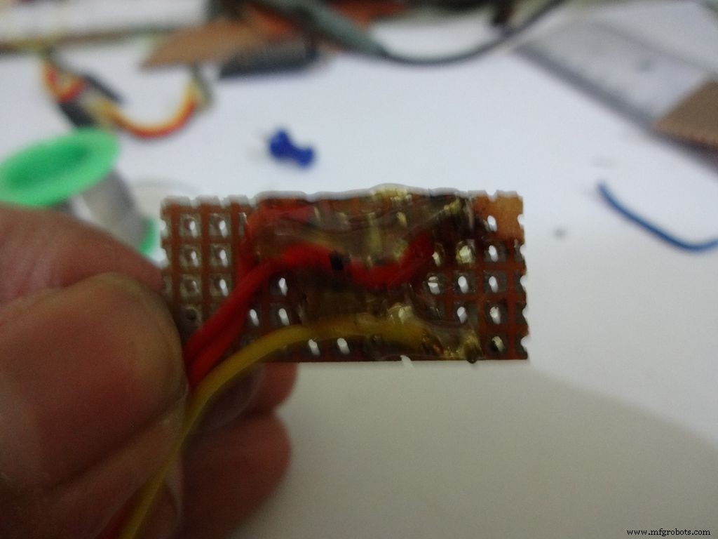
Secure it with hot glue as shown
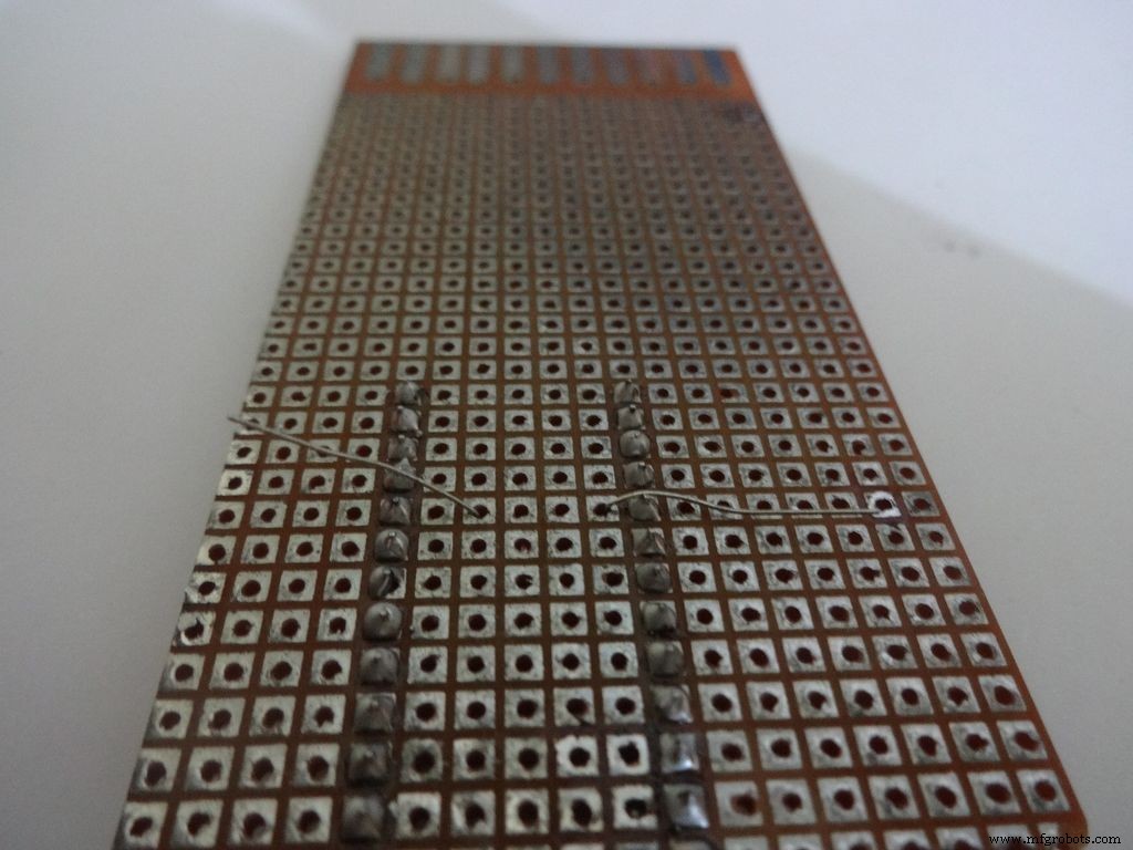
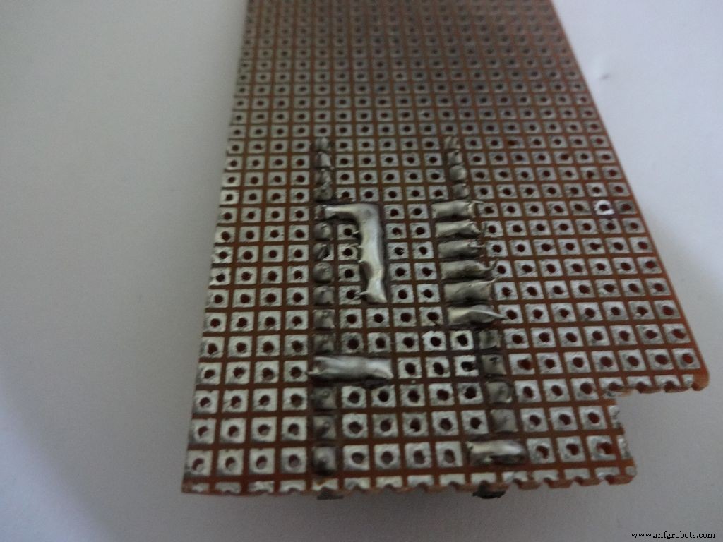
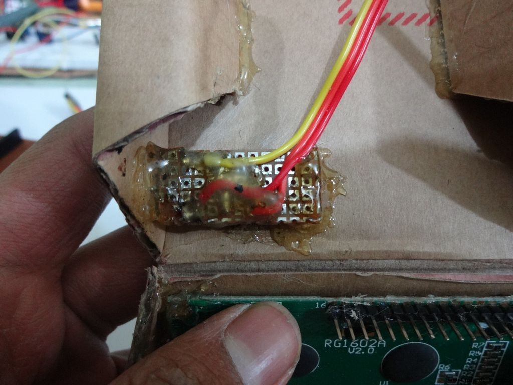
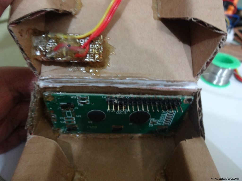
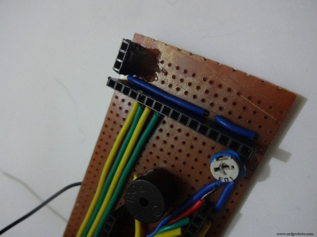
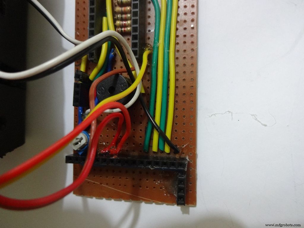
Step 22:Making the Case -- Testing points
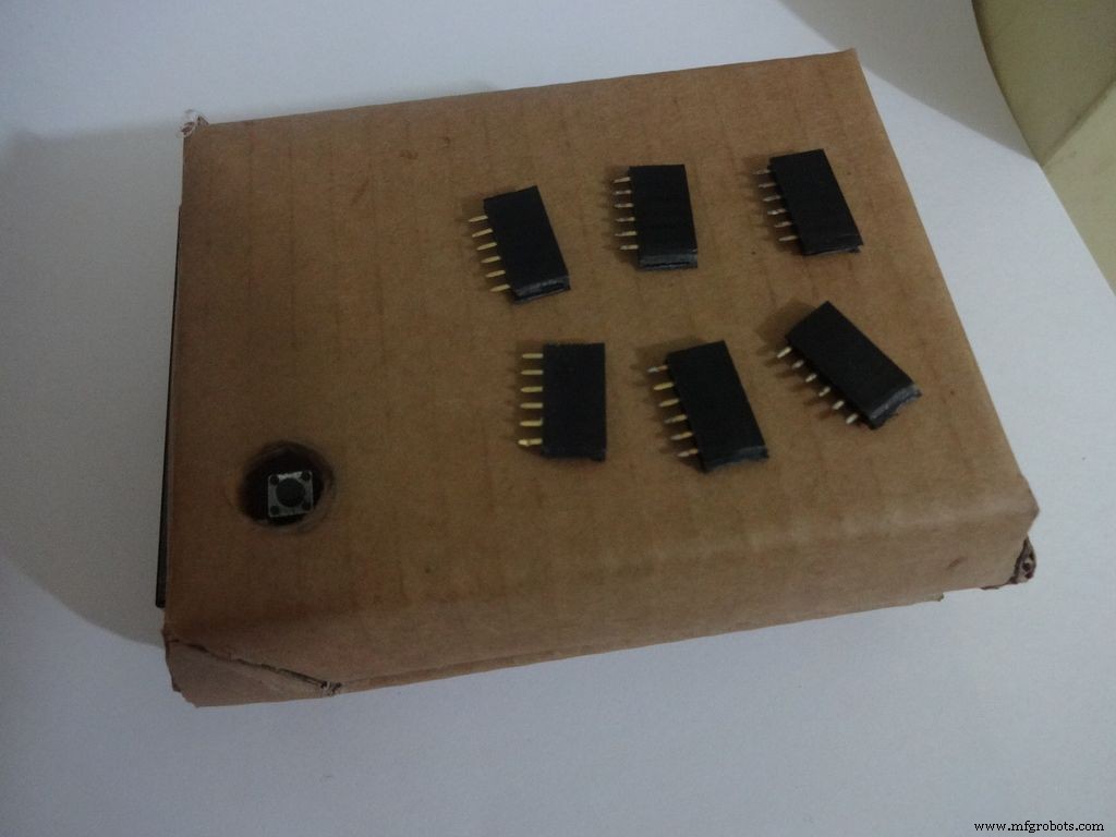
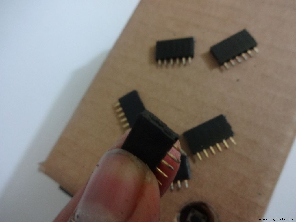
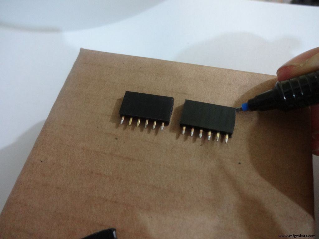
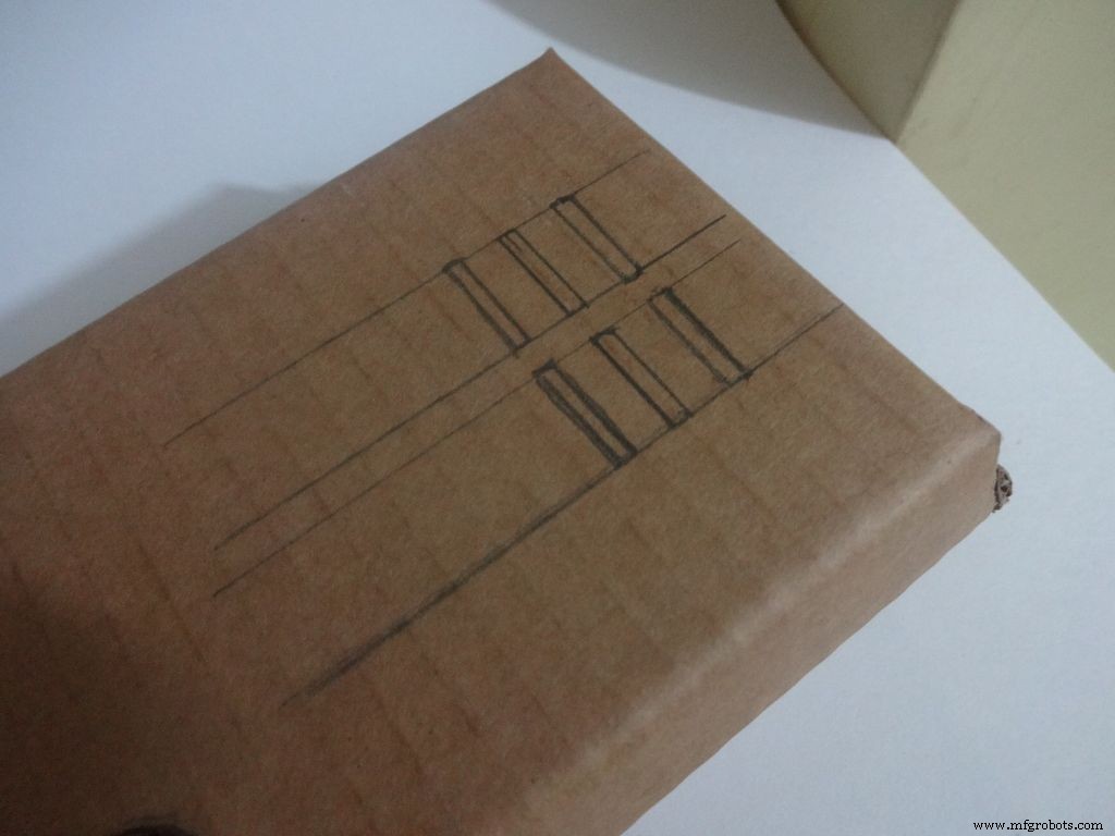
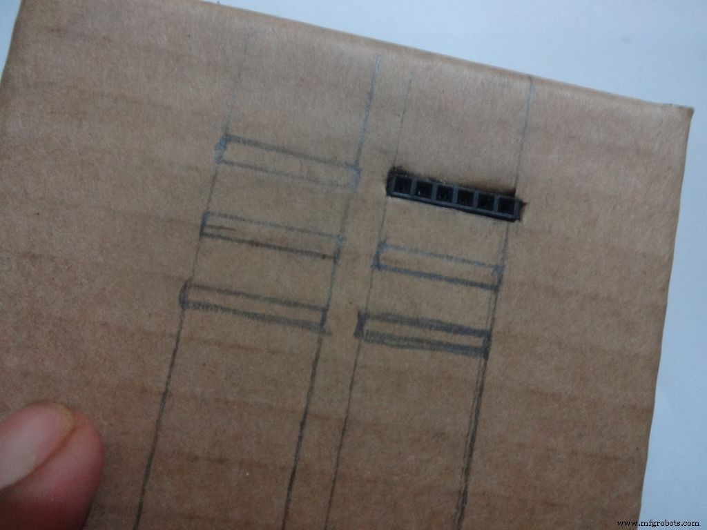
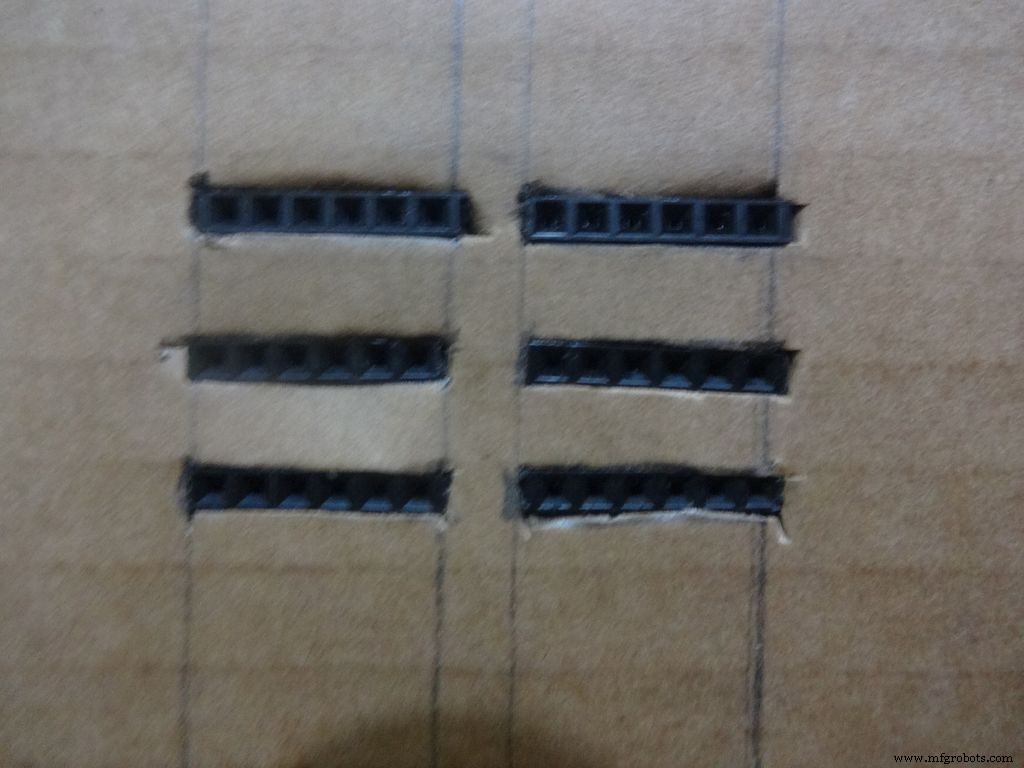
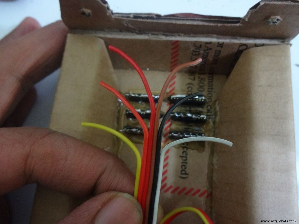
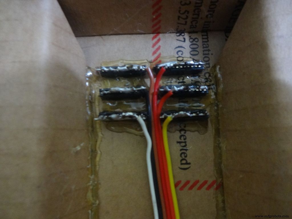
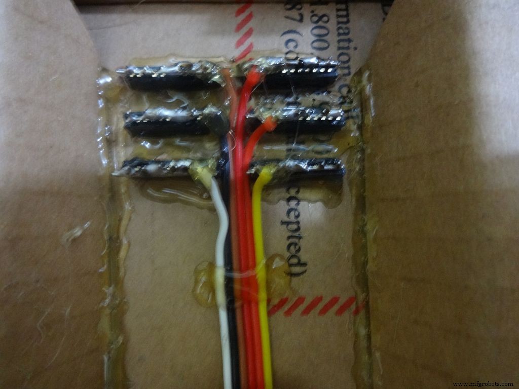
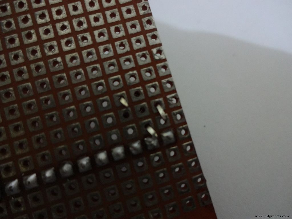
Cut 6x 6pin female header pins. Sand the sides to make it smooth.
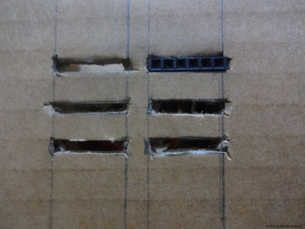
Mark the positions and cut slots for the header pins. Insert it in place and glue it from the inside.
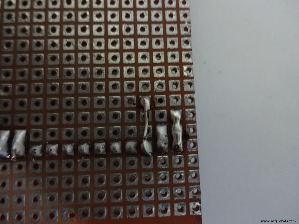
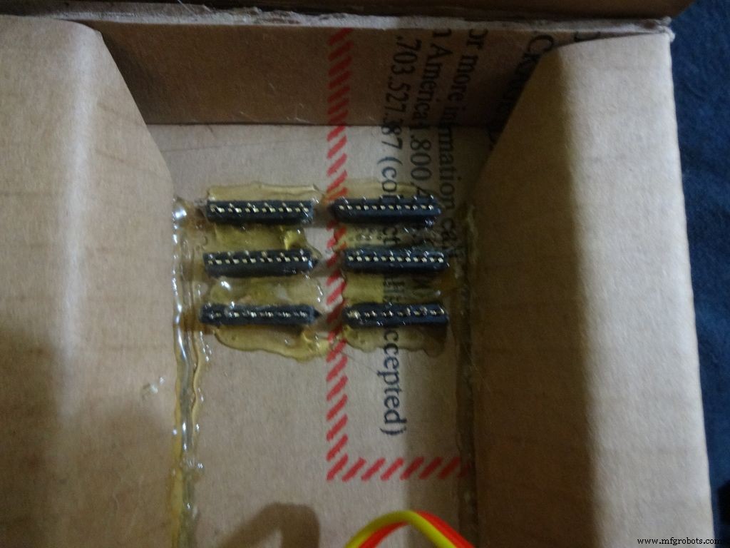
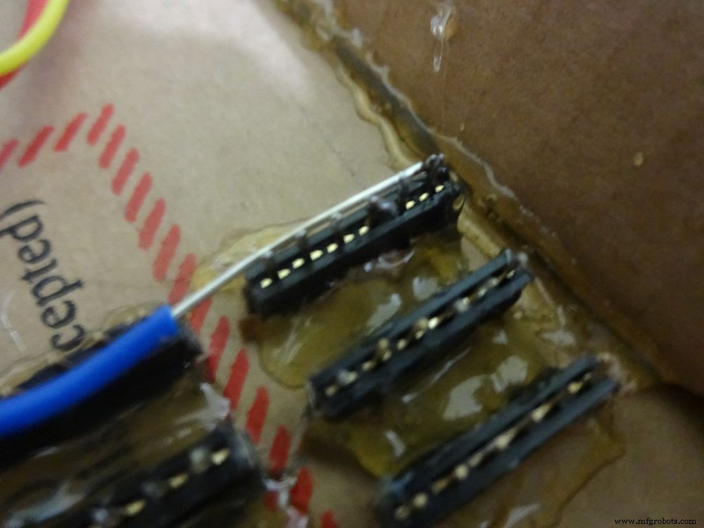
Apply small amounts of solder to all the pins and use a stripped jumper to get it all together. Make sure all of them are connected. Dont keep on heating it to make it perfect. Heating a pin also heats the neighbouring ones.
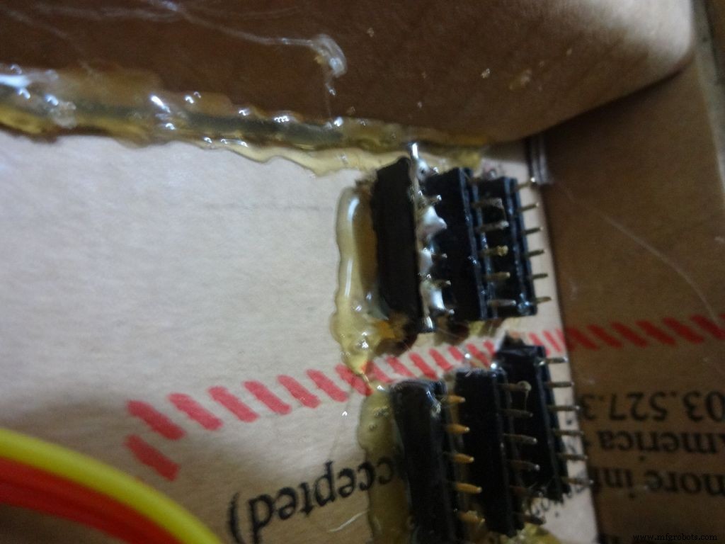
Take 6 stranded ribbon cable, tin it and attach it to each slot. Note that I put dark colours to the negative side. Apply hot glue to fix them in place.
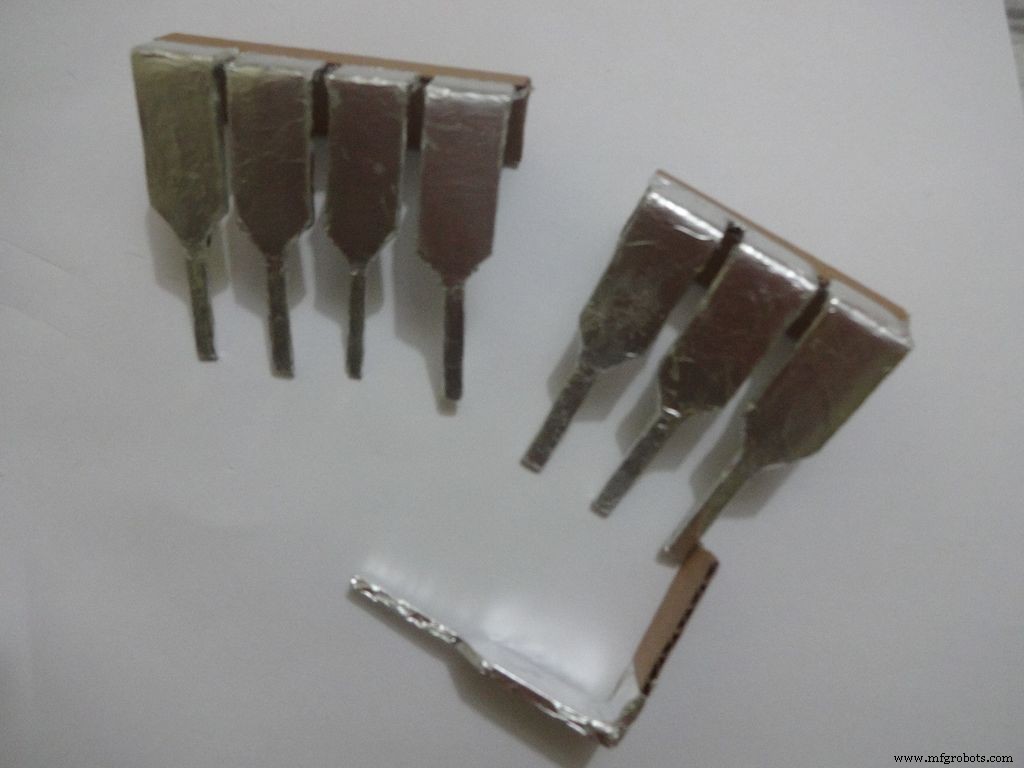
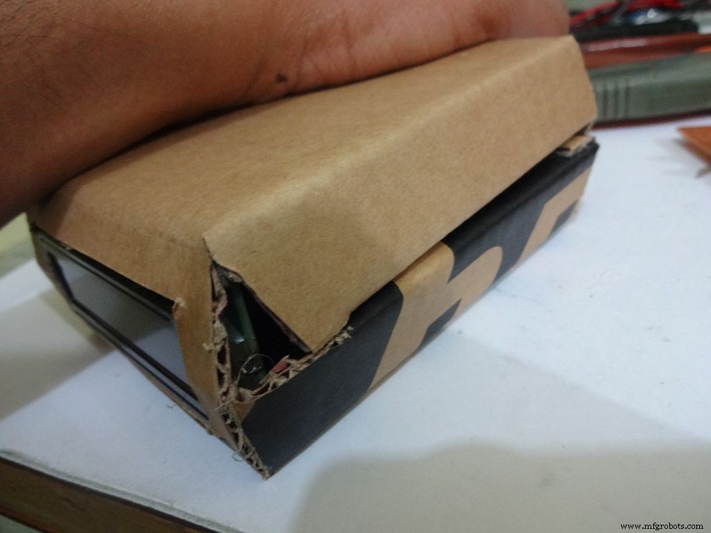
Step 23:The Legs


Download "Legs_A4.pdf" or ""Legs_ANSI_A.pdf", based of paper size available in your region. attached at the end.
Print it on an A4 size paper (21 x 29.7cm or 8.27 x 11.69 inches) or the US-alternative ANSI A(8.5 x 11inches or 21.6 × 27.9cm). Make sure that while printing you select the proper paper size, orientation, and select the "Actual Size" option. Confirm that the print is accurate by measuring the rectangle. It should be 8.4 x 11.8cm
Cut crease and glue it just like the main case, see the images.
Step 24:Making it shiny!
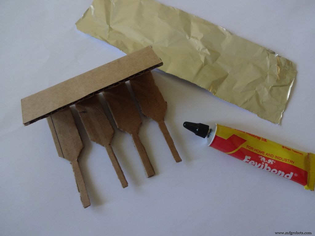
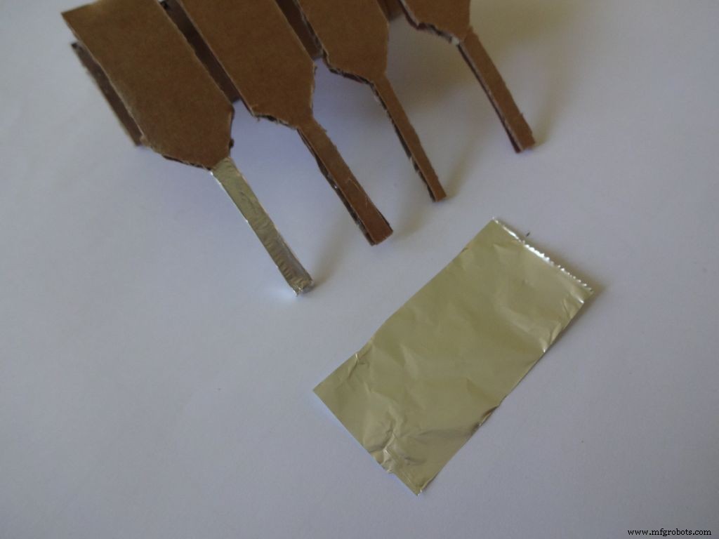
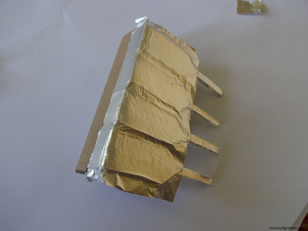
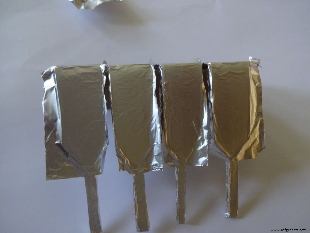
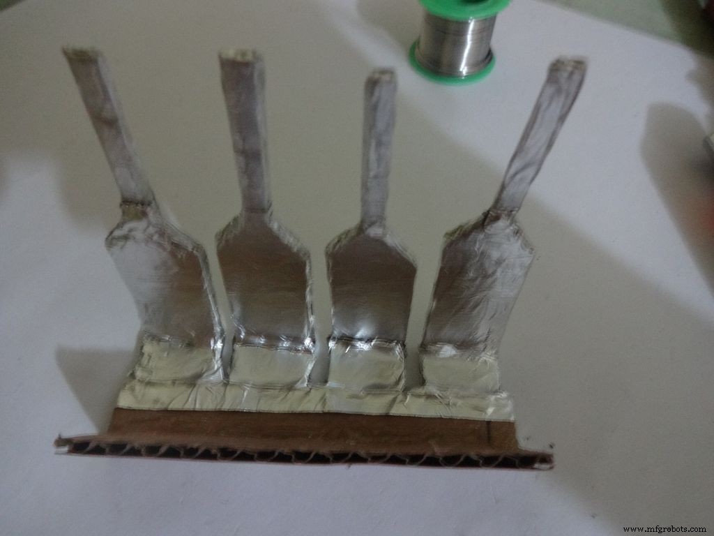
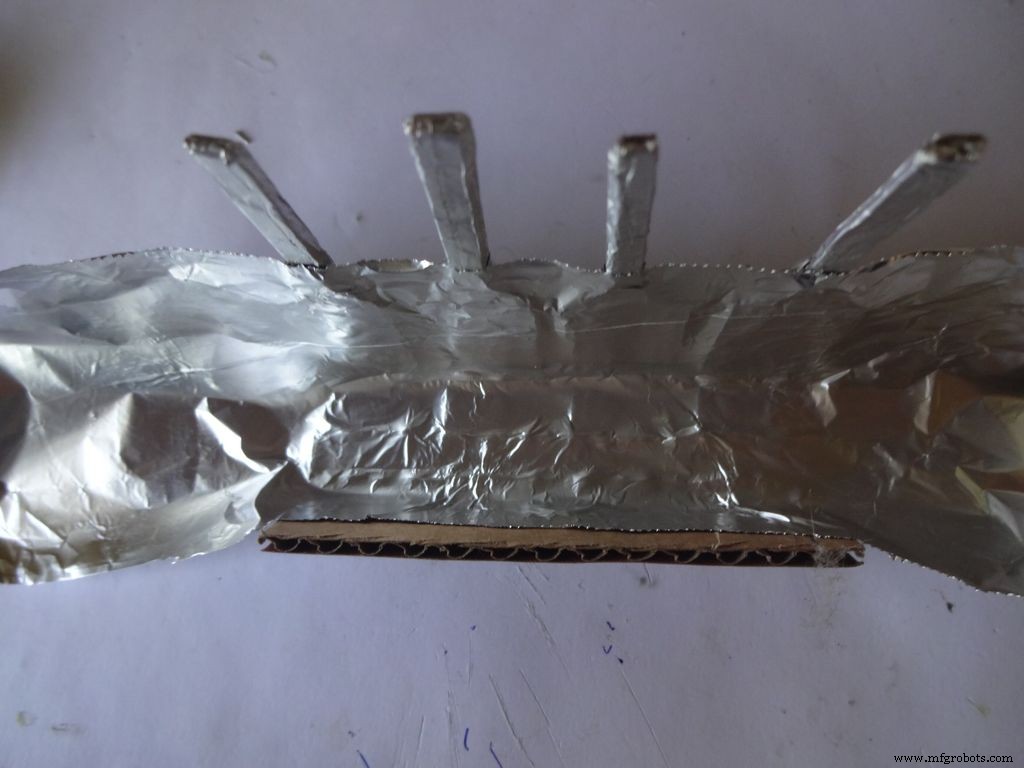
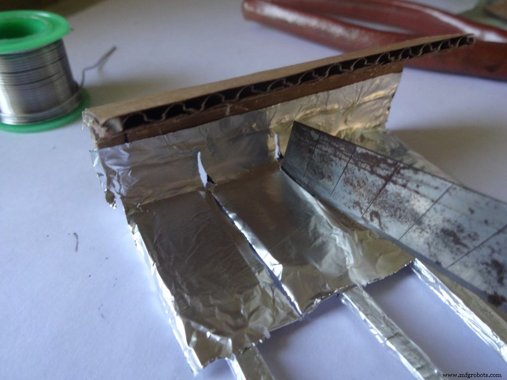

Cut a piece of foil 1x2inches and stick it carefully, fold by fold to the leg ends with some metal-cardboard sticking glue. I used Fevibond.
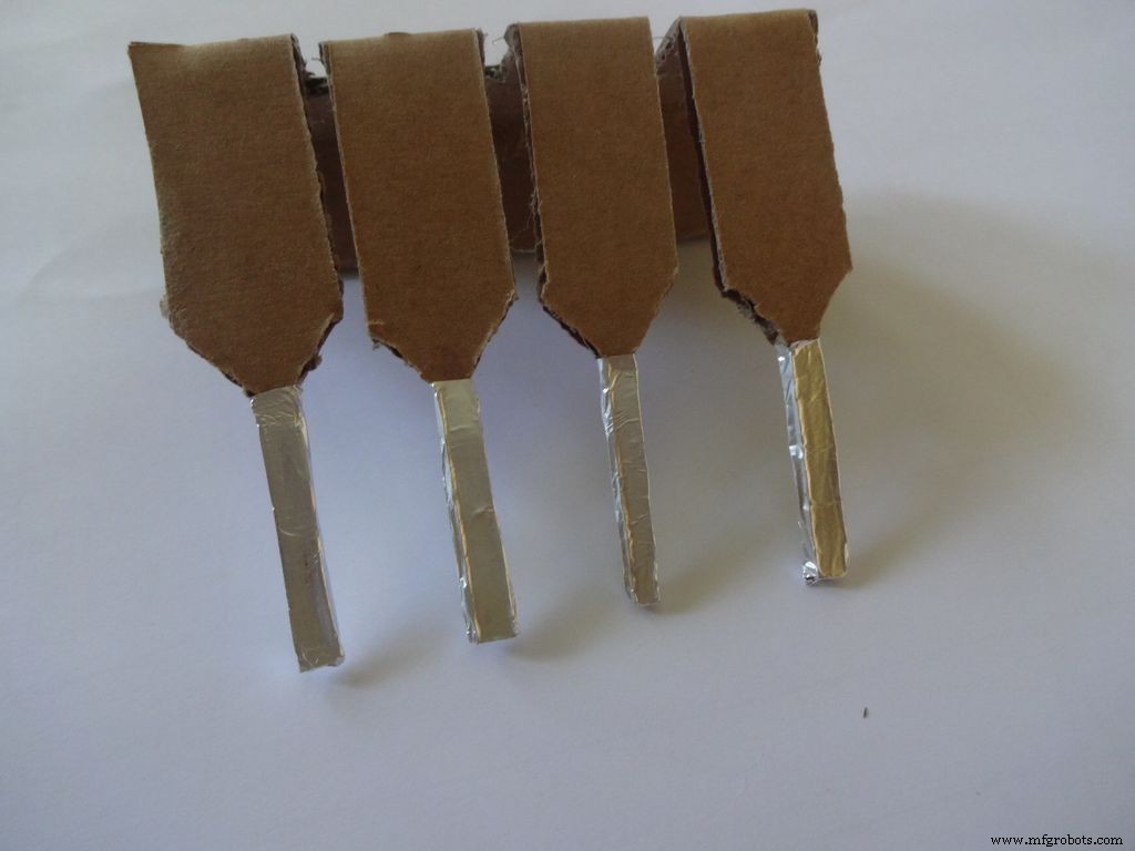
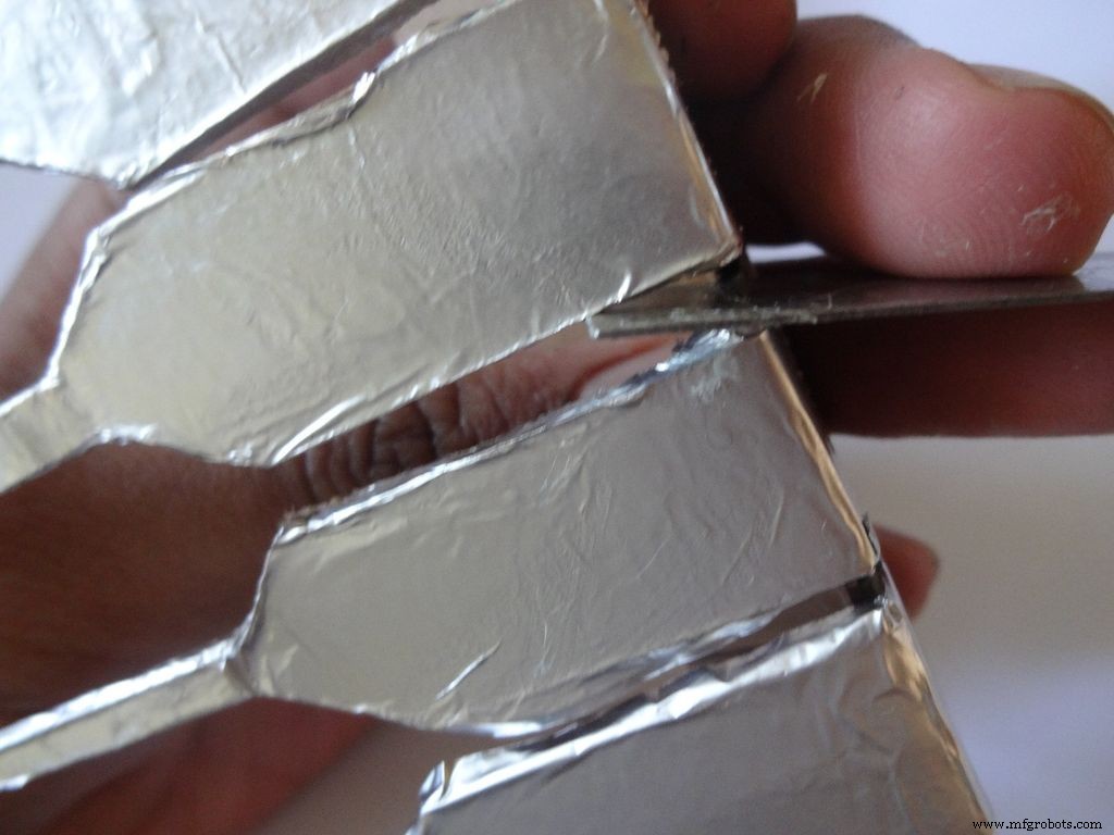
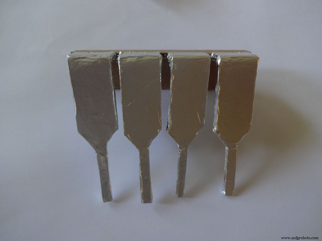
Next stick a patch that covers all the leg tops(as shown), make cuts slowly with a cutter. Do this carefully. The foil tends to tear to the sides. Use something flat to stick the foil in between the legs and give it a good finish.
Now cover it with transparent cello tape, just like you applied the foil, to protect it from sharp objects.
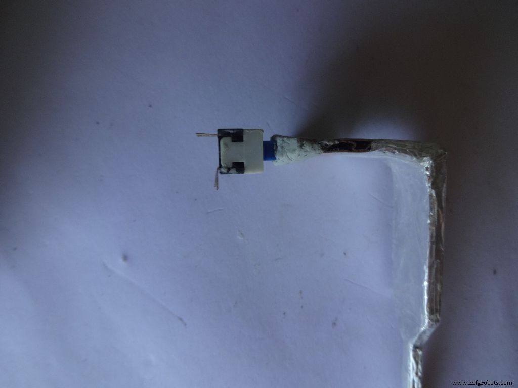
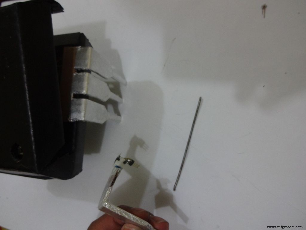
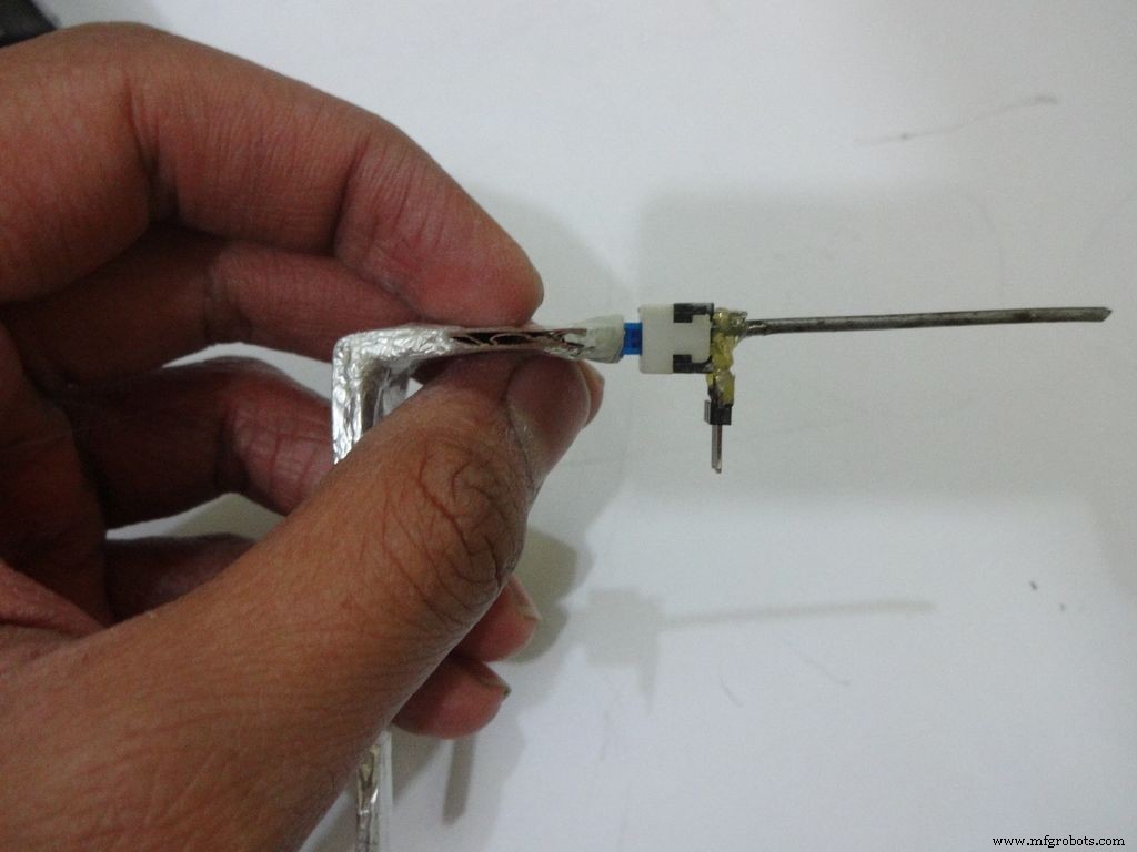
Step 25:The Power Switch
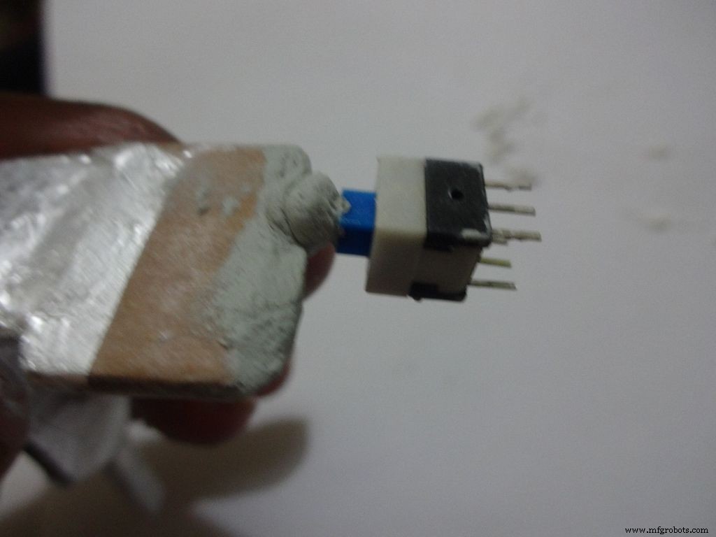
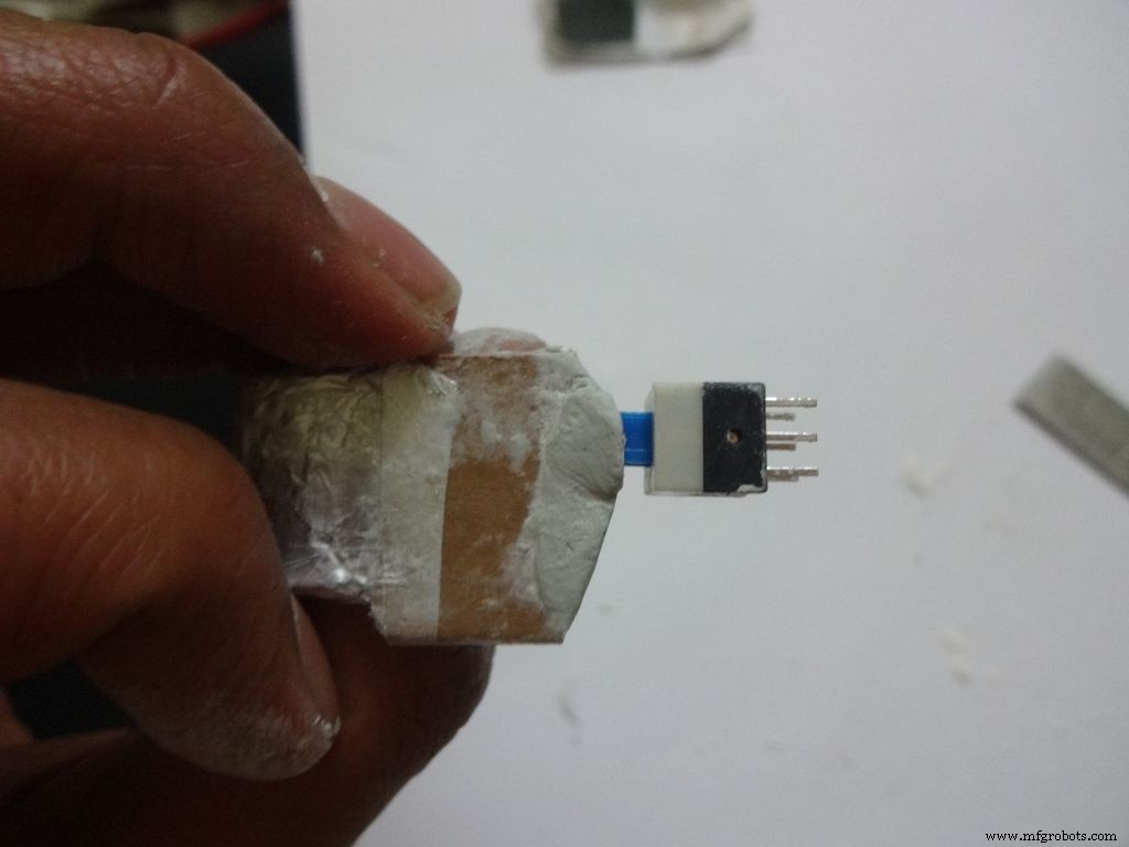
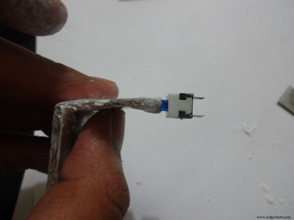
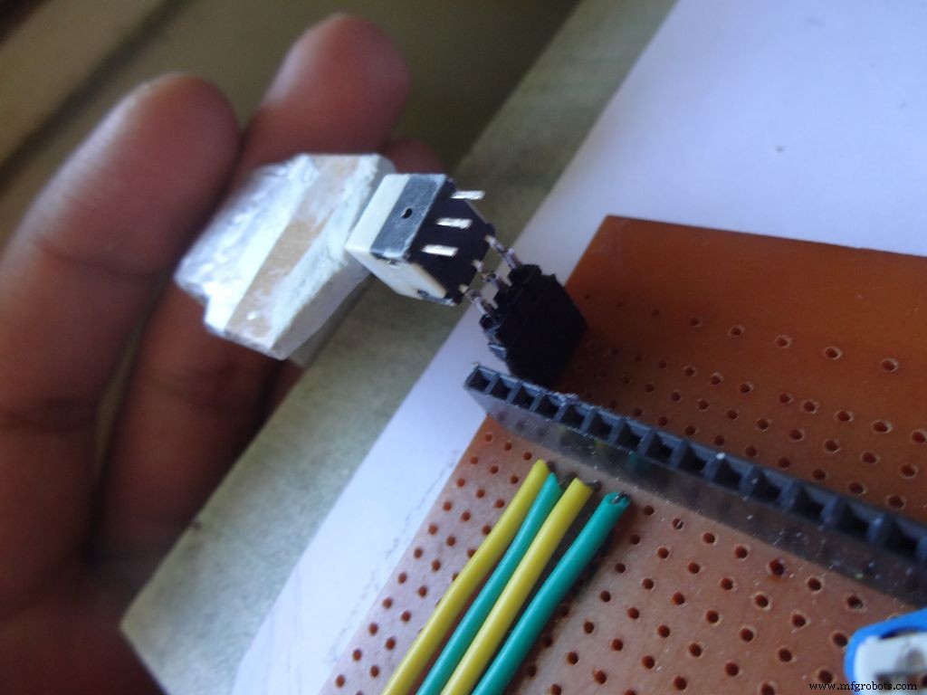
Measure and cut the power switch leg by properly keeping it in place. Temporarily stick the other pins with tape to get the pin1 position right.
Mix the m-seal(epoxy putty sealant, gets very hard when it dries) well. Put it as shown in the images and use powder+flat surface to shape it. Let it dry.
Also fill any gaps left in your case.
Note:We cant use hot glue here as it is rubbery and the switch needs to be stuck with some strong brittle material.
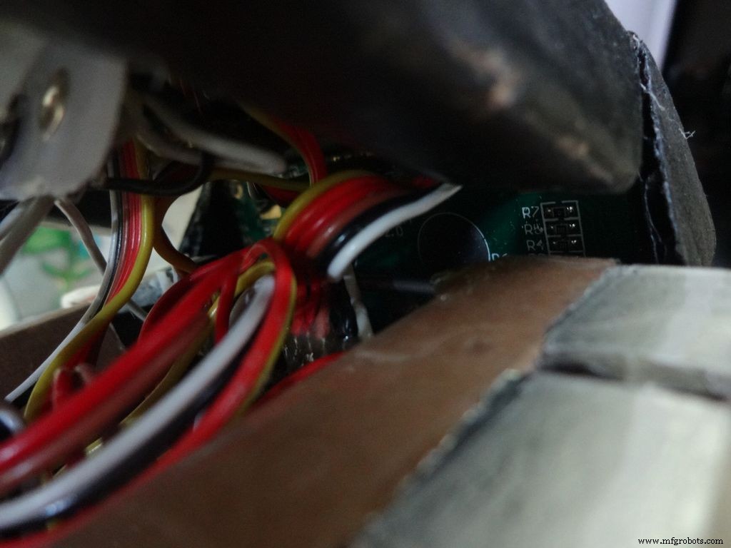
Step 26:Power switch to PCB

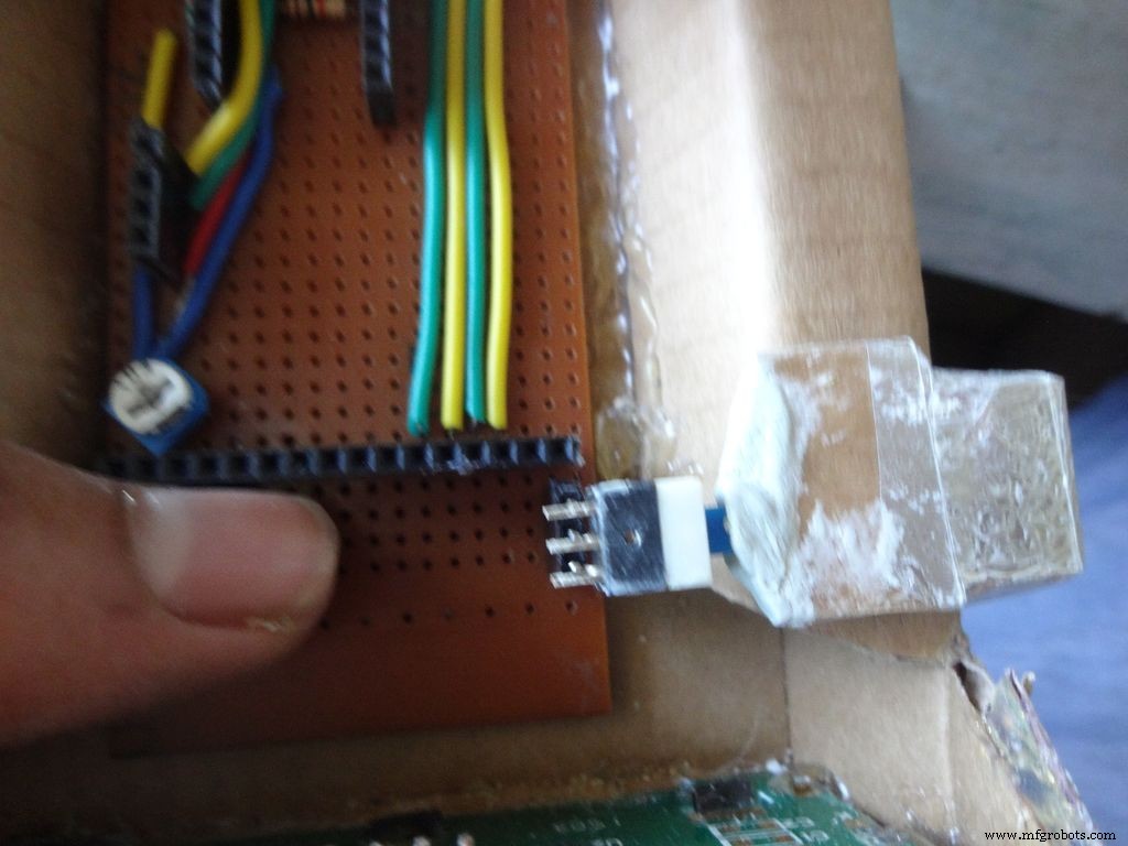
After The m-seal dries, place it in to check if everythings alright.
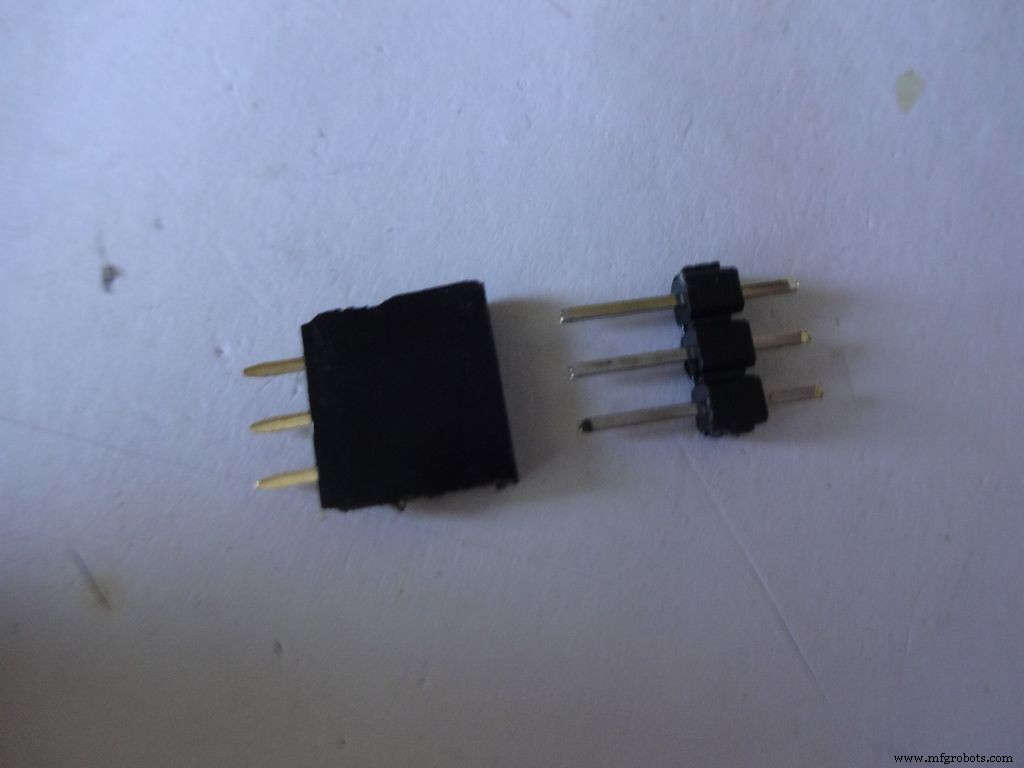
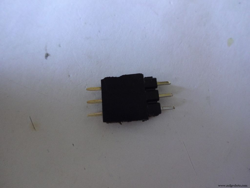
Cut 3pins of female and male headers place it on the PCB such that it aligns with the switch pins. Solder the female part.
Tin the switch leads and the male header pins, join them. See if it fits at the right place.
Try pushing the switch on and off after placing a finger behind the switch for support. We will add a support rod later on.
Connect a side pin of female header(power switch) to Vin. I realised this late and had to undergo lots of trouble.
Secure the header Pin with hot glue.
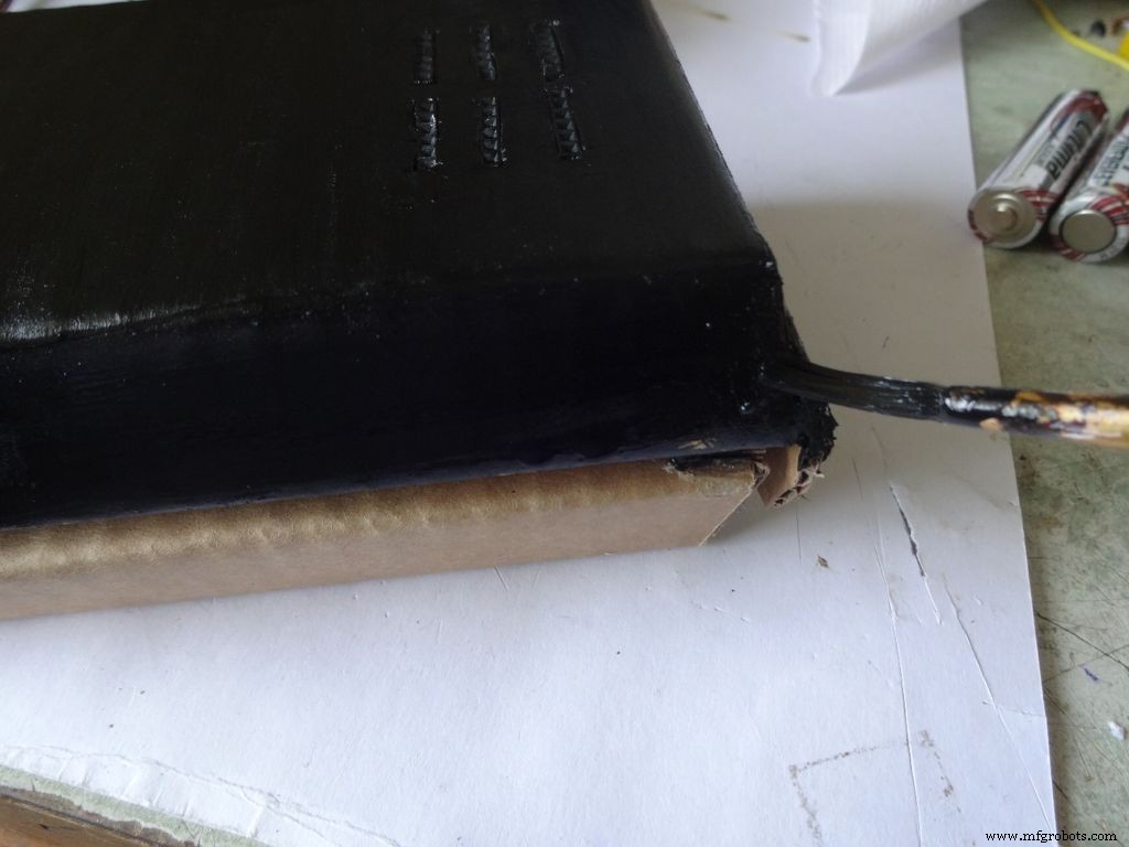
Step 27:Making the USB Port

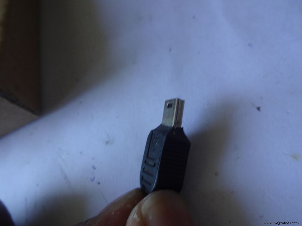
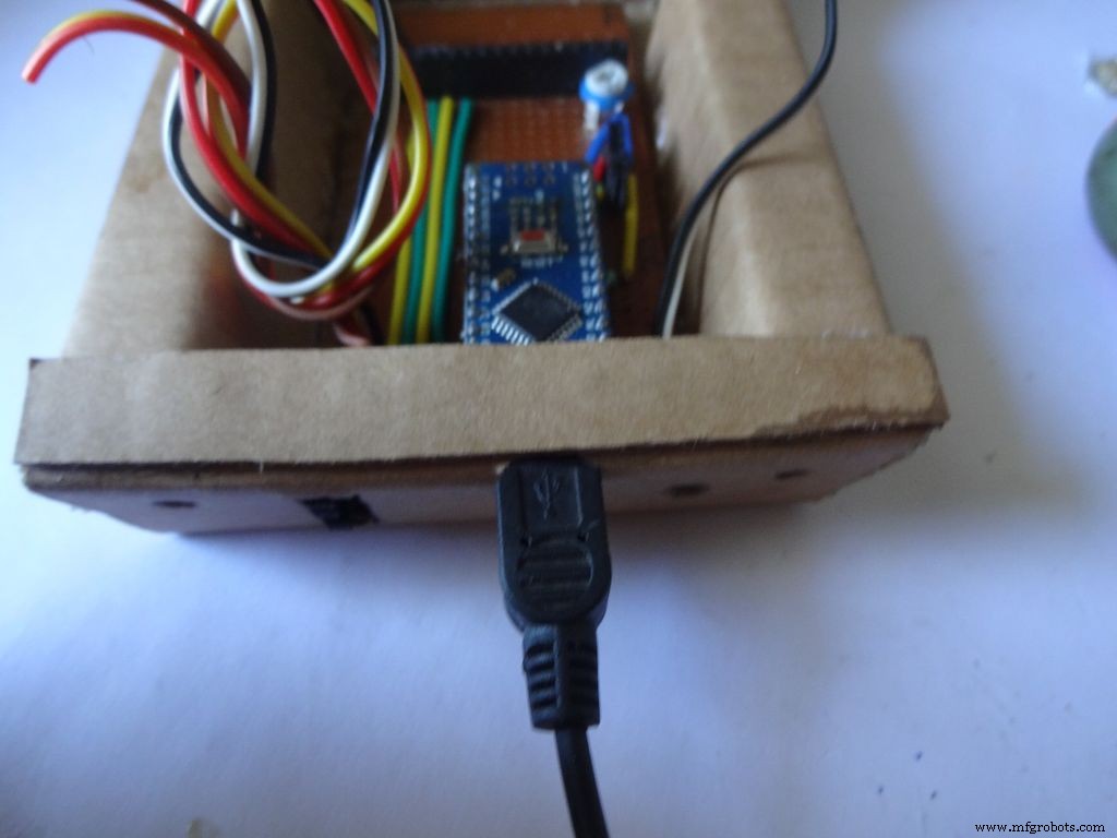
Put the PCB properly in (with Arduino) and cut a rectangle for the mini USB port.
Remove some plastic from the USB cable so that it fits the Arduino properly. Test whether connection is proper.
Step 28:Some other things...

I removed all the LEDs from the Arduino Nano and also the power LED on my RTC module. These consume unnecessary power, which matters if you are operating on a battery.
Sand the dried m-seal so that it mixes smoothly with the cardboard. Clean the powder with a wet paper napkin before painting.
I also added a buzzer which may be used for some functions. Buzzers are sensitive, don't use too much heat while soldering!
Step 29:Time to paint!
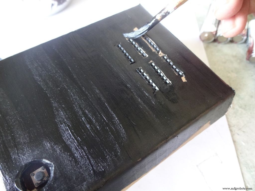
Dont use direct thick paint while painting, this cases brush patterns to appear. Use sufficient water.
Make sure no tiny bubbles are formed. These form when you dab the brush too much.
Dont paint the cover hinge, the paint will restrict it.
This is just a base coat. Another layer of paint will be added while finishing up.
Step 30:Soldering all the wires
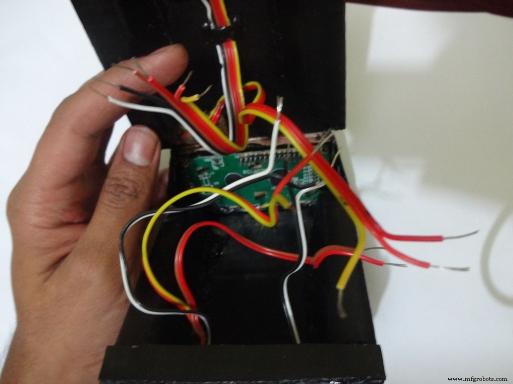
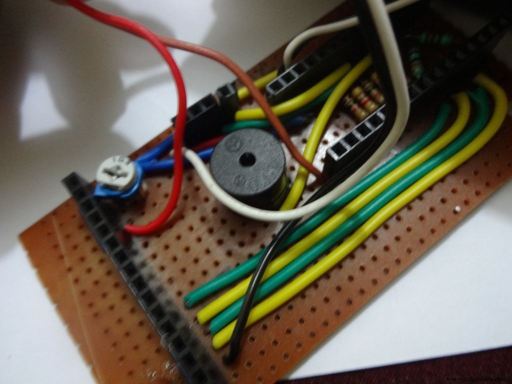
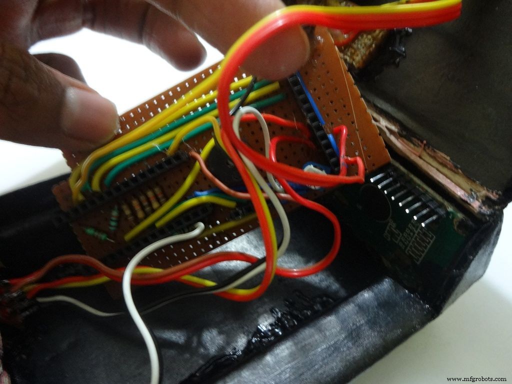
Make sure you refer the circuit design before making any connections.
First connect the reset switch, one end to RST and one end to GND.
Then, the backlight switch. One end to +5V and other end to 'A' or Anode of the backlight LED. Also connect 'K', Cathode to GND.
Next is the RS switch, connect one end to RS and other to pin D1(TX).
And finally the Enable switch. Connect one end to 'E' or Enable and other end to pin D0(RX).
Switches
Where to?
Reset - pushbutton RST and GND Backlight - slide +5V and A RS - slide D1 (TX) and RS Enable - slide D0 (RX) and E
Note:Pins D0 and D1 are connected through switches as keeping them connected sometimes causes problems while using Serial(for debugging).
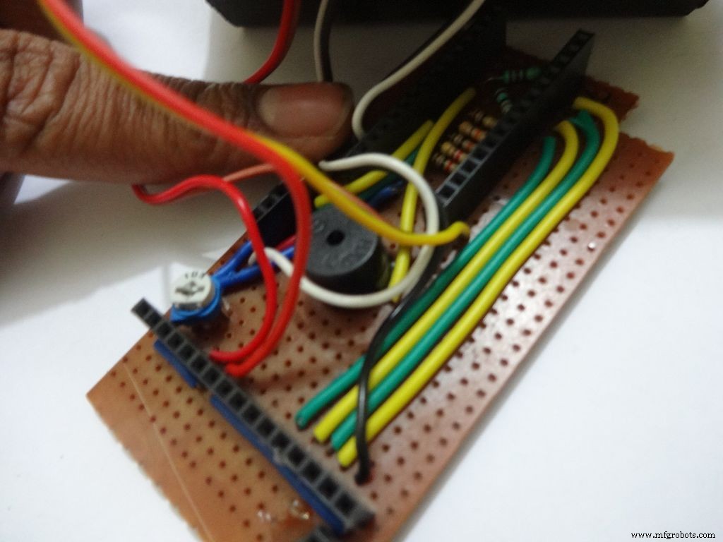
This completes the base wiring. Apply hot glue after double checking the connections.
Then connect the 3 wires of mode change button:The 10k pulldown resistor to GND. 220 Ohm resistor to pin D11 and input pin to +5V or VCC
Finally connect the 6 wires from the test slots to their appropriate places(shown in images).
Positive
Negative
Resistance Test A7 GND Capacitance Test A0 GND Diode Test A6 D12
Note:All the +5Vs and GNDs are same and hence connect to most convinient spot.
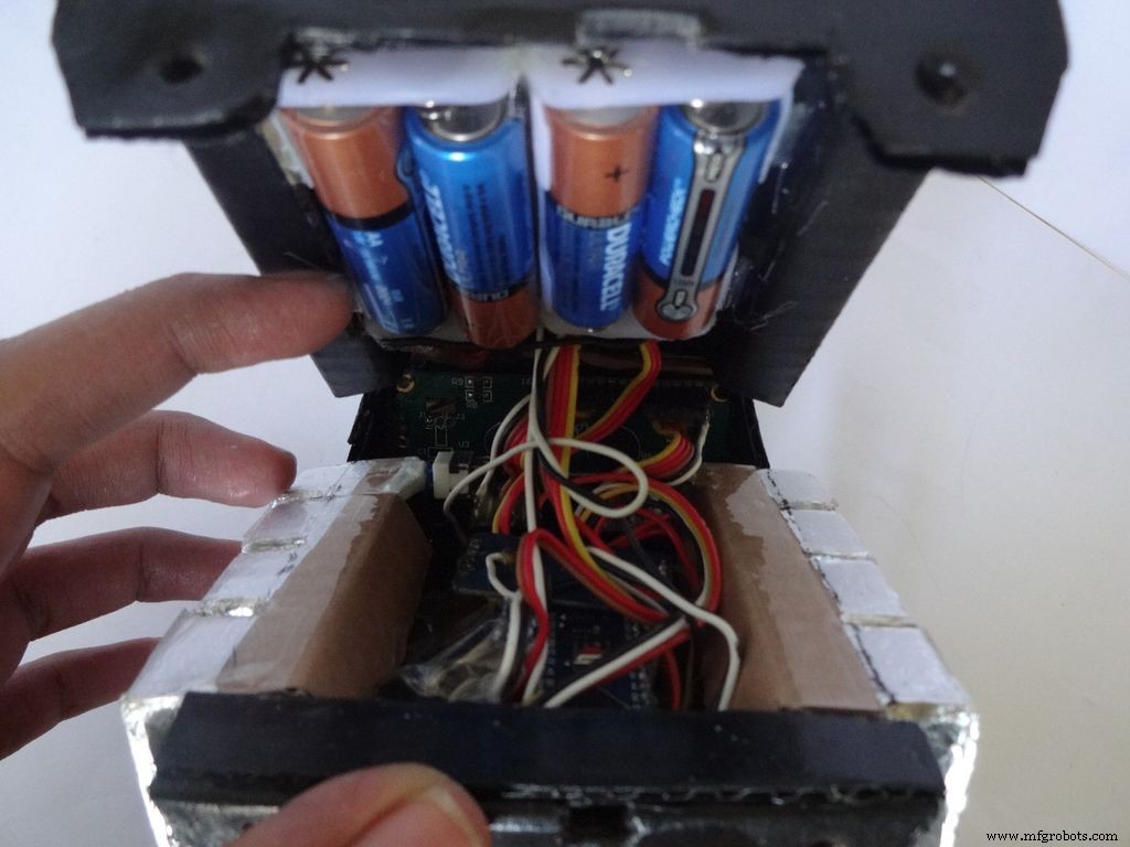
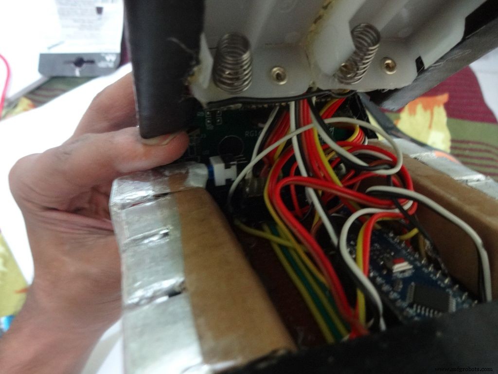
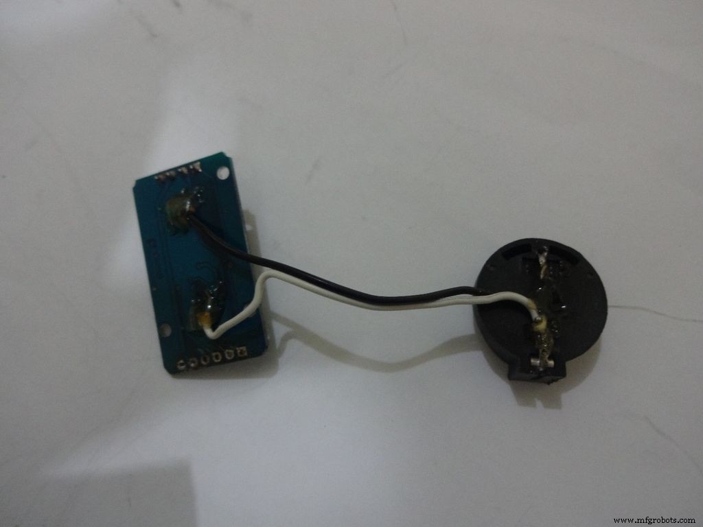
Step 31:Adding the battery case
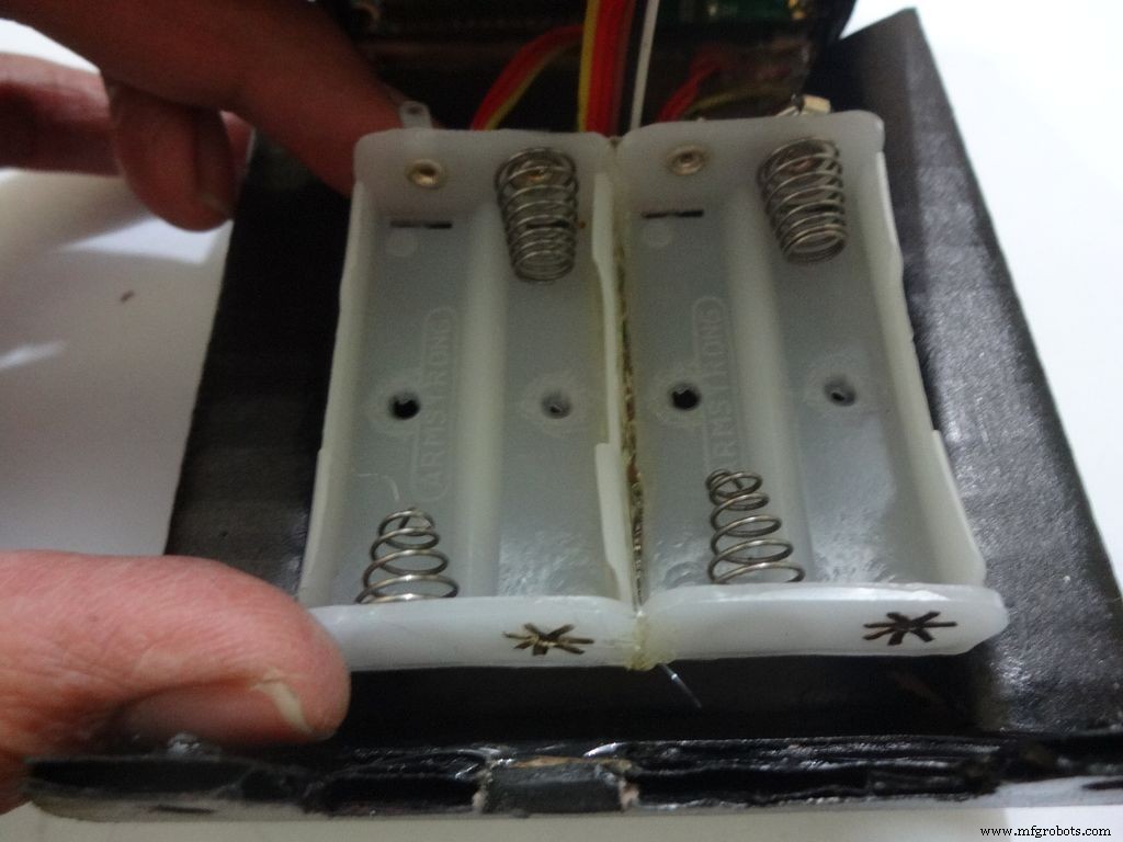
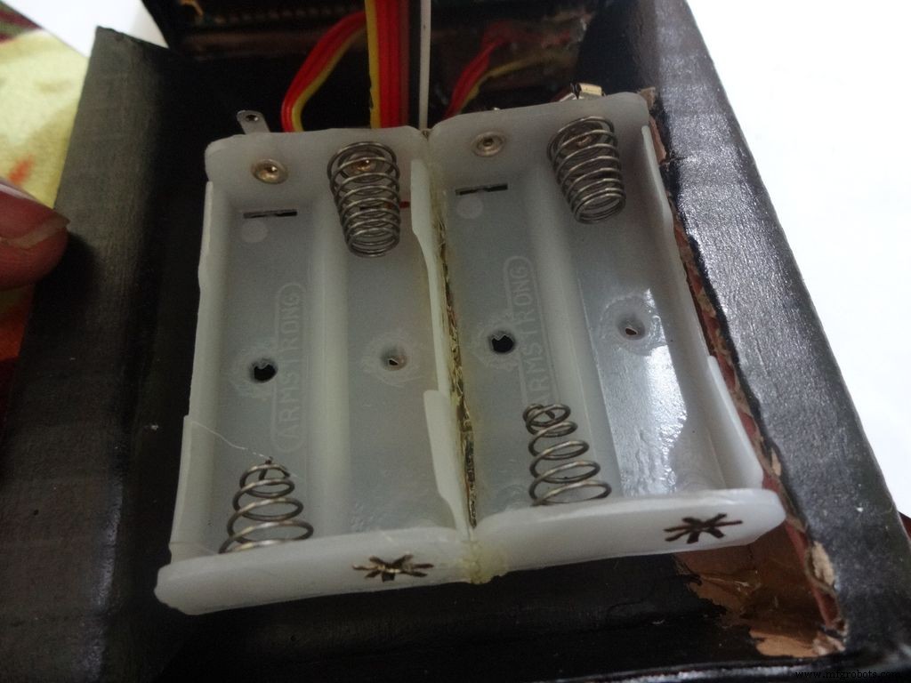

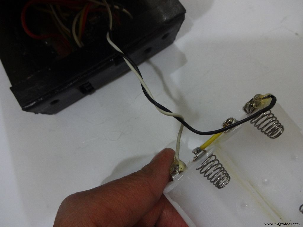
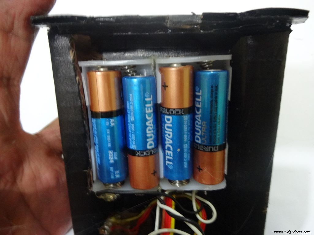
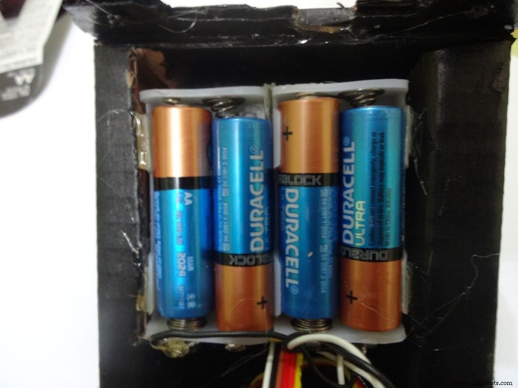
Place the battery case at the top cover, make cuts to place it inside such that the cover can be closed properly.
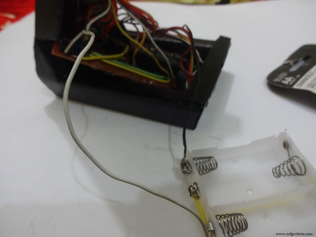
Solder Wires to the case, strip and tin them. Solder the positive end to the middle pin of power switch and negative end to ground.
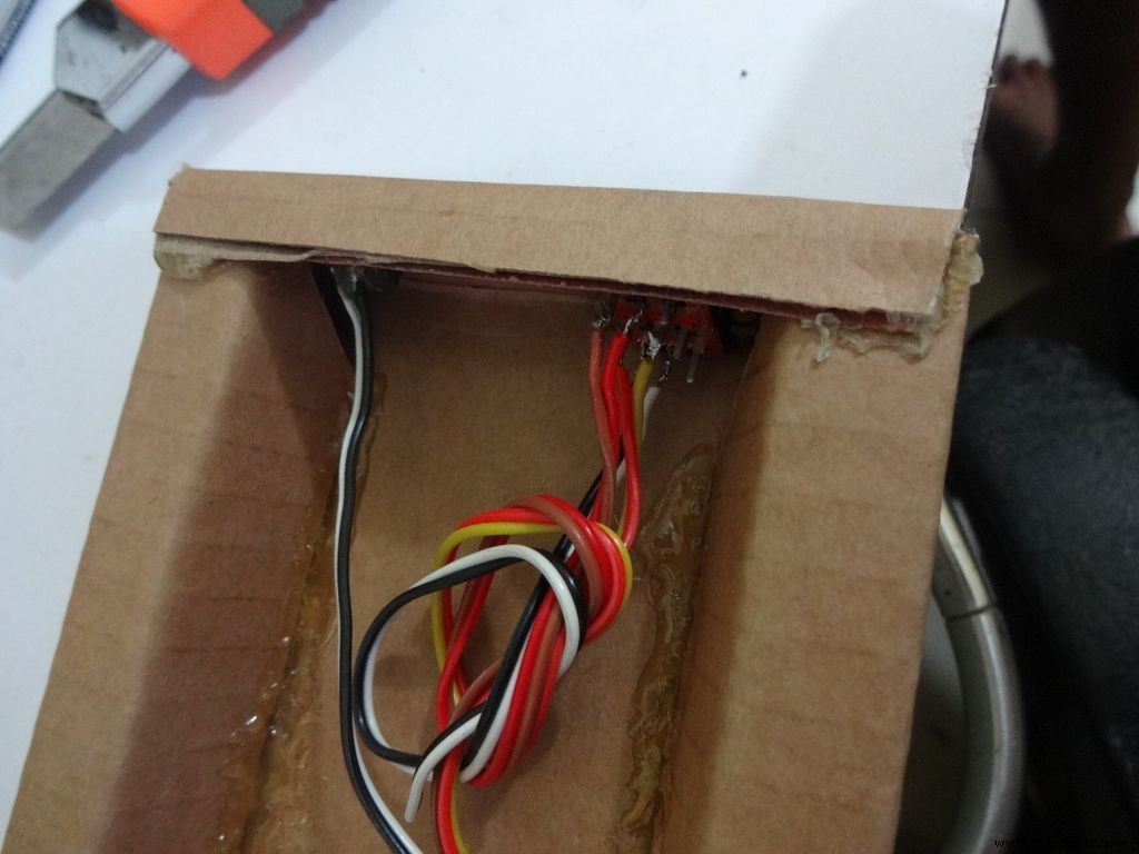
Glue the PCB to the base after making all the connections.
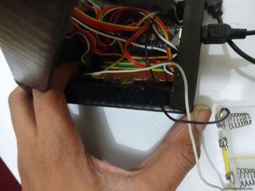
Twist the wires and place them in position. Insert batteries(the case expands a bit on inserting batteries) and glue the case to the cover.
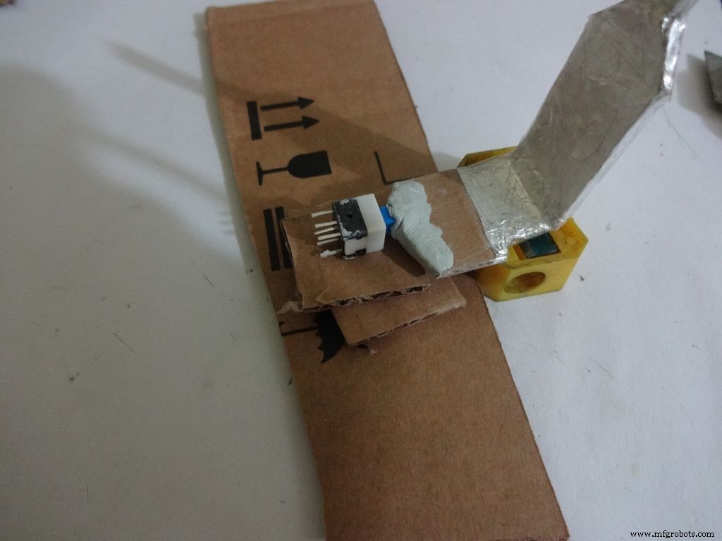
Step 32:Adding the Legs
Cut the inner part of legs so that it fits in properly. Stick it it place.
Put the power switch pin in to check if it fits in perfectly. Remove it, add a metal rod, piece of wood or anything strong of proper length that will prevent the switch from moving back. Glue it in place.
Check the switch, it should be turning on/off smoothly.
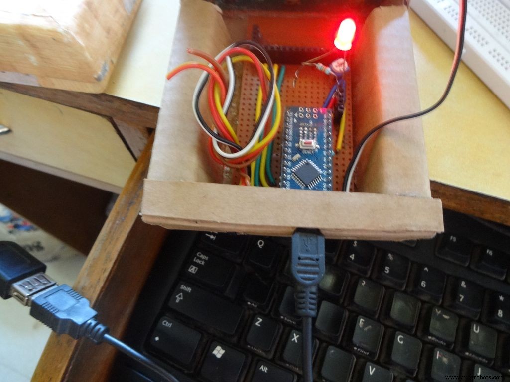
Switch on the IC and test all the functions. If its not working skip to the troubleshooting section.
Step 33:Finishing up!
Use M-seal (or equivalent) to fill any small gaps around the testing area and the mode change button. After drying, sand it well and apply a second layer of paint.
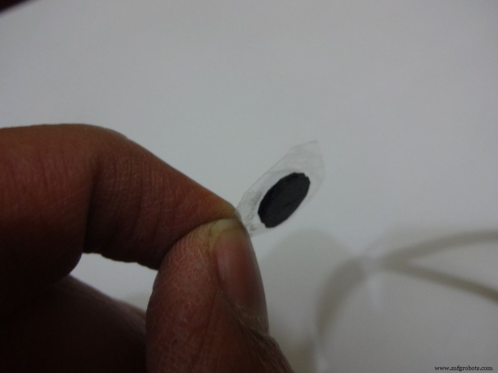
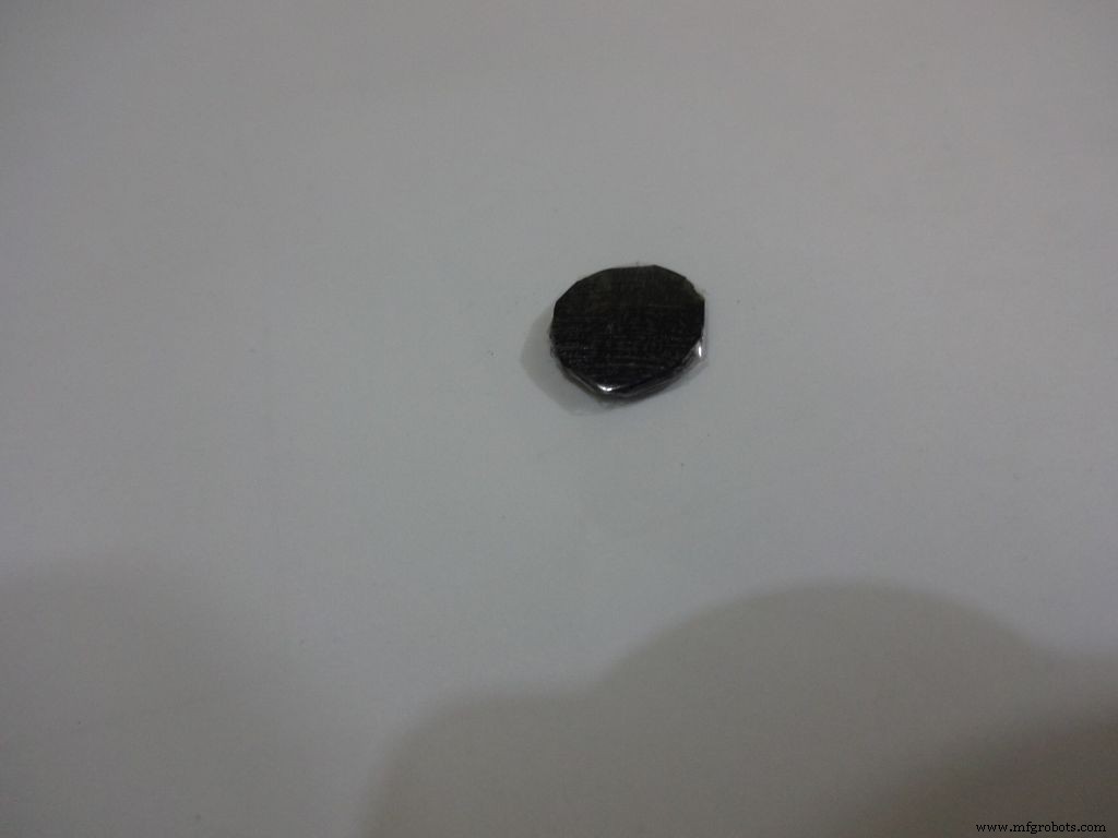
Make the button with a small piece of cardboard, paint it black and cover it with tape(gives a shiny finish). Apply a tiny drop of glue and stick the button in place.
Step 34:Problems and Troubleshooting

Do everything correctly. This is the most boring most of any project and you dont wanna get here just because you soldered the wrong pins!
Step 35:Things I did, some mistakes I made
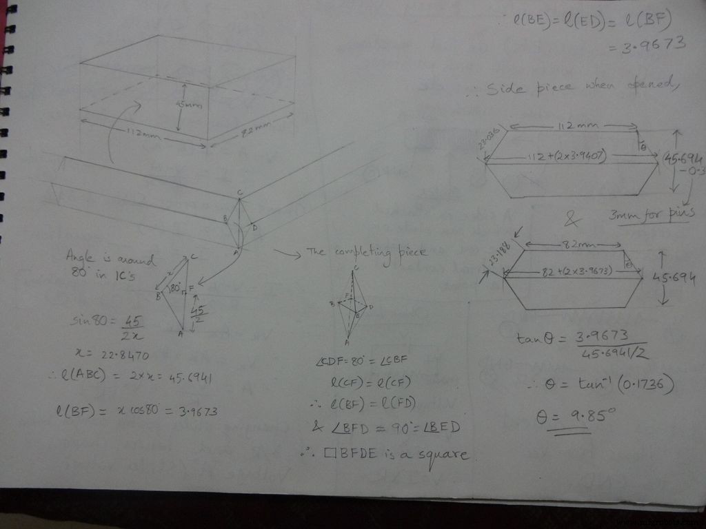

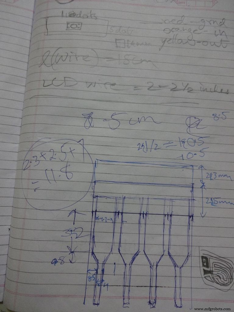
While testing the various circuits and when I had the rough idea of what I want to make, I decided to go with the IC design. I measured actual ICs, took ratios of their lengths, got the angle with some trignometry to be around 80 degrees. Then I decided the inner box length and breadth and built upon it(shown in image). Once the layout was planned, I initially started to draw it accurately on a large size paper. After a bit of a struggle of drawing accurate lines, I realised that this kind of work should be done on a computer! So I learnt CAD basics and succesfully made the layout on it. :) But this layout didnt work out and I had to redo the entire cutting and making of the case.(See images)
While removing the LEDs on the Arduino Nano I used excess pressure to remove a stubborn LED, and ended up removing a PCB pad. Always desolder without forcing/applying pressure on the joints, the pads are delicate and easily come off if you dont stay calm.
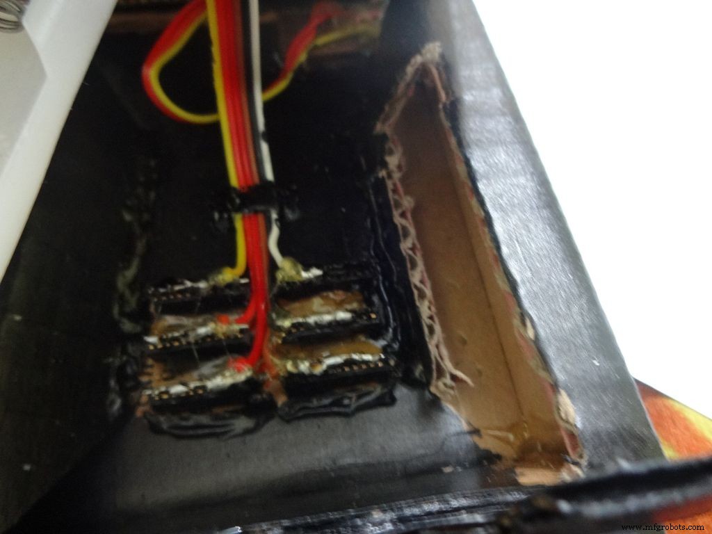
When all the solder joints were made and project was about to get finished, in excitement and eagerness, I glued the PCB inside the case before adding the battery case. Had to re-melt the hot glue with a soldering iron (carefully not to melt any wire insulation) and remove the PCB out to solder the battery case wires in. The soldering iron can be cleaned afterwards.
The RTC module battery was coming in way of the batteries while closing and so I separated the battery holder(Warning:desolder only with the battery removed) and added extension wires so that the battery can be placed at the sides where there is space.
All the Layout PDFs, CAD Files and the Main code can be downloaded here:Google Drive
//Analog pin used to find resistanceint Apin=7;//values of r1 to r5float r1=1000;float r2=4700;float r3=10000;float r4=47000;float r5=100000;//pins of r1 to r5int r1_pin=2;int r2_pin=3;int r3_pin=4;int r4_pin=5;int r5_pin=6;float reading=0; //read from analog pin and store herefloat R=0; //calculate unknown and store hereString finalR; //final value to be displayed along with unitsint caseno; //for debugging, stores the case number // we divide the entire range into cases and assign each a number, // total 5 cases // case1 :less than 2850 // case2 :2850 to 7350 // case3 :7350 to 28500 // case4 :28500 to 73500 // case5 :more than 73500#include// needed for converting float to string, //has the String(float,n) function. Explained below.void setup() { Serial.begin(9600);}void loop() { //first we find unknown resistance using 1kOhm resistor //Therefore, disable R2, R3, R4 and R5 digitalWrite(r2_pin, LOW); //turn each pin to LOW before setting it as INPUT pinMode(r2_pin, INPUT); // turning it to INPUT when its HIGH enables the // internal pullup resistor digitalWrite(r3_pin, LOW); pinMode(r3_pin, INPUT); digitalWrite(r4_pin, LOW); pinMode(r4_pin, INPUT); digitalWrite(r5_pin, LOW); pinMode(r5_pin, INPUT); pinMode(r1_pin, OUTPUT); digitalWrite(r1_pin, HIGH); //read and calculate resistance reading=analogRead(Apin); R=(reading*r1)/(1023-reading); // if value <2850, finalR =value(using 1kOhm) if(R<2850){ caseno=1; if(R<1000){ //if value less than 1000 use "Ohm" not "kOhm" finalR =String(R,2) + "Ohm"; //String(float,n) Converting float to string //with n digits after decimal // attach "Ohm" after value to the string, //'+' joins two strings here } else{ //use "kOhm R=R/1000; finalR =String(R,2) + "kOhm"; } } //if value between 2850 and 7350 , use value obtained by 4.7kOhm else if(R>=2850 &&R<7350){ caseno=2; digitalWrite(r1_pin, LOW); //Enable only 4.7kOhm pinMode(r1_pin, INPUT); digitalWrite(r3_pin, LOW); pinMode(r3_pin, INPUT); digitalWrite(r4_pin, LOW); pinMode(r4_pin, INPUT); digitalWrite(r5_pin, LOW); pinMode(r5_pin, INPUT); pinMode(r2_pin, OUTPUT); digitalWrite(r2_pin, HIGH); reading=analogRead(Apin); R=(reading*r2)/(1023-reading)/1000; finalR =String(R,2) + "kOhm"; } //if value between 7350 and 28500, use value obtained by 10kOhm else if(R>=7350 &&R<28500){ caseno=3; digitalWrite(r1_pin, LOW); pinMode(r1_pin, INPUT); digitalWrite(r2_pin, LOW); pinMode(r2_pin, INPUT); digitalWrite(r4_pin, LOW); pinMode(r4_pin, INPUT); digitalWrite(r5_pin, LOW); pinMode(r5 _pin, INPUT); pinMode(r3_pin, OUTPUT); digitalWrite(r3_pin, HIGH); reading=analogRead(Apin); R=(reading*r3)/(1023-reading)/1000; finalR=String(R,2) + "kOhm"; } //if value between 28500 and 73500, use value obtained by 47kOhm else if(R>=28500 &&R<73500){ caseno=4; digitalWrite(r1_pin, LOW); pinMode(r1_pin, INPUT); digitalWrite(r2_pin, LOW); pinMode(r2_pin, INPUT); digitalWrite(r3_pin, LOW); pinMode(r3_pin, INPUT); digitalWrite(r5_pin, LOW); pinMode(r5_pin, INPUT); pinMode(r4_pin, OUTPUT); digitalWrite(r4_pin, HIGH); reading=analogRead(Apin); R=(reading*r4)/(1023-reading)/1000; finalR =String(R,2) + "kOhm"; } //if value more than 73500, use value obtained by 100kOhm else if(R>=73500){ caseno=5; digitalWrite(r1_pin, LOW); pinMode(r1_pin, INPUT); digitalWrite(r2_pin, LOW); pinMode(r2_pin, INPUT); digitalWrite(r3_pin, LOW); pinMode(r3_pin, INPUT); digitalWrite(r4_pin, LOW); pinMode(r4_pin, INPUT); pinMode(r5_pin, OUTPUT); digitalWrite(r5_pin, HIGH); reading=analogRead(Apin); R=(reading*r5)/(1023-reading)/1000; finalR =String(R,2) + "kOhm"; } Serial.println(finalR); //printing the final string with units Serial.println(" "); penundaan (1000); }
/* RCTiming_capacitance_meter * code concept taken from Paul Badger 2008 * * The capacitor's voltage at one time constant is defined as * 63.2% of the charging voltage. * i.e, A Capacitor is filled to 63.2% of its total capacity in * 1 Time Constant */ int analogPin=0; // analog pin for measuring capacitor voltage int chargePin=7; // pin to charge the capacitor - connected to // one end of the charging resistor int dischargePin=12; // pin to discharge the capacitor, // same used for diode test(checkPin1) float resistorValue=10000.0; // We use 10kOhm resistor unsigned long startTime; unsigned long elapsedTime; float microFarads; // floating point variable to preserve precision float nanoFarads;void setup(){ pinMode(chargePin, OUTPUT); // set chargePin to output digitalWrite(chargePin, LOW); Serial.begin(9600); // initialize serial transmission for debugging}void loop(){ digitalWrite(chargePin, HIGH); // set chargePin HIGH and capacitor charging startTime =millis(); while(analogRead(analogPin) <648){ // just wait and do nothing till 648 // 647 is 63.2% of 1023, // which corresponds to full-scale voltage } elapsedTime=millis() - startTime; // convert milliseconds to seconds ( 10^-3 ) // and Farads to microFarads ( 10^6 ), net 10^3 (1000) microFarads =((float)elapsedTime / resistorValue) * 1000; // (float) converts "unsigned long" elapsed time to float Serial.print(elapsedTime); // print the value to serial port Serial.print(" mS "); // print units if (microFarads> 1){ Serial.print((long)microFarads); // print the value to serial port Serial.println(" microFarads"); // print units } else { // if value is smaller than one microFarad, convert to nanoFarads (10^-9 Farad). nanoFarads =microFarads * 1000.0; // multiply by 1000 to convert to nanoFarads (10^-9 Farads) Serial.print((long)nanoFarads); // print the value to serial port Serial.println(" nanoFarads"); // print units } /* dicharge the capacitor */ digitalWrite(chargePin, LOW); // set charge pin to LOW pinMode(dischargePin, OUTPUT); // set discharge pin to output digitalWrite(dischargePin, LOW); // set discharge pin LOW while(analogRead(analogPin)> 0){ // wait until capacitor is completely discharged } pinMode(dischargePin, INPUT); // set discharge pin back to input} String state ="null"; //prints "null" for reverse bias or nothing connectedint checkPin1 =12;int checkPin2 =6;void setup() { Serial.begin(9600);}void loop() {pinMode(checkPin1, OUTPUT); digitalWrite(checkPin1, LOW); //pin 11 is set to low//analog read is normally pulled up by the 10k resistor, so null reading is 1023//In forward bias, the analog pin gets connected to checkPin1, which is LOW. So reading less than 1023//Practically a small current flows in reverse bias as well, so we take 700 to differentiate if(analogRead(checkPin2)<700){ state="forward"; } Serial.println(state); Serial.println(analogRead(checkPin2)); state ="null"; delay(500);} // Date and time functions using a DS1307 RTC connected via I2C and Wire lib#include #include RTC_DS1307 rtc;//creating "rtc" object of RTC_DS1307, objects are used to access functions //more on objects and classes:https://www.youtube.com/watch?v=ABRP_5RYhqUchar daysOfTheWeek[7][12] ={"Sunday", "Monday", "Tuesday", "Wednesday", "Thursday", "Friday", "Saturday"};void setup () { Serial.begin(9600); rtc.begin(); // following line sets the RTC to the date &time this sketch was compiled // rtc.adjust(DateTime(F(__DATE__), F(__TIME__))); // This line sets the RTC with an explicit date &time, for example to set // January 21, 2014 at 3am you would call:// rtc.adjust(DateTime(2014, 1, 21, 3, 0, 0));}void loop () { DateTime now =rtc.now(); Serial.print(now.year()); Serial.print('/'); Serial.print(now.month()); Serial.print('/'); Serial.print(now.day()); Serial.print(" ("); Serial.print(daysOfTheWeek[now.dayOfTheWeek()]); Serial.print(") "); Serial.print(now.hour()); Serial.print(':'); Serial.print(now.minute()); Serial.print(':'); Serial.print(now.second()); Serial.println(); Serial.println(); delay(1000);} Proses manufaktur
Komponen dan persediaan Arduino Nano R3 × 1 Penguat operasional IC TL061 × 1 Resistor 10k ohm × 2 Resistor 1M ohm × 1 Kapasitor Cakram Keramik, 39 pF × 1 kumparan sekunder dari trafo 1-2W kecil × 1 Alat dan mesin yang diperlukan
Komponen dan persediaan Arduino UNO × 1 Adafruit LCD Standar - 16x2 Putih di Atas Biru × 1 Sakelar Tombol Tekan SparkFun 12mm × 4 Resistor 10k ohm × 4 Resistor 221 ohm Yah, 220 ohm... × 2 Potensiometer Putaran Tunggal- 100k ohm × 1
Komponen dan persediaan Arduino UNO × 1 Adafruit LCD Standar - 16x2 Putih di Atas Biru × 1 Sakelar Tombol Tekan SparkFun 12mm × 1 Ukuran Setengah Papan Tempat Memotong Roti Perma-Proto × 1 Kabel jumper (generik) × 1 Resistor 1k ohm × 1
Mencampur istilah atau jargon adalah hal biasa dalam elektronik, terutama ketika berbicara tentang transistor vs resistor. Namun, masalahnya tidak hanya terletak pada bagaimana kami memilih untuk menamainya. Ini adalah fungsi mereka yang mungkin membingungkan pemula. Kami memiliki daftar lengkap se