Tentang proyek ini
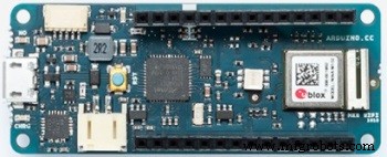
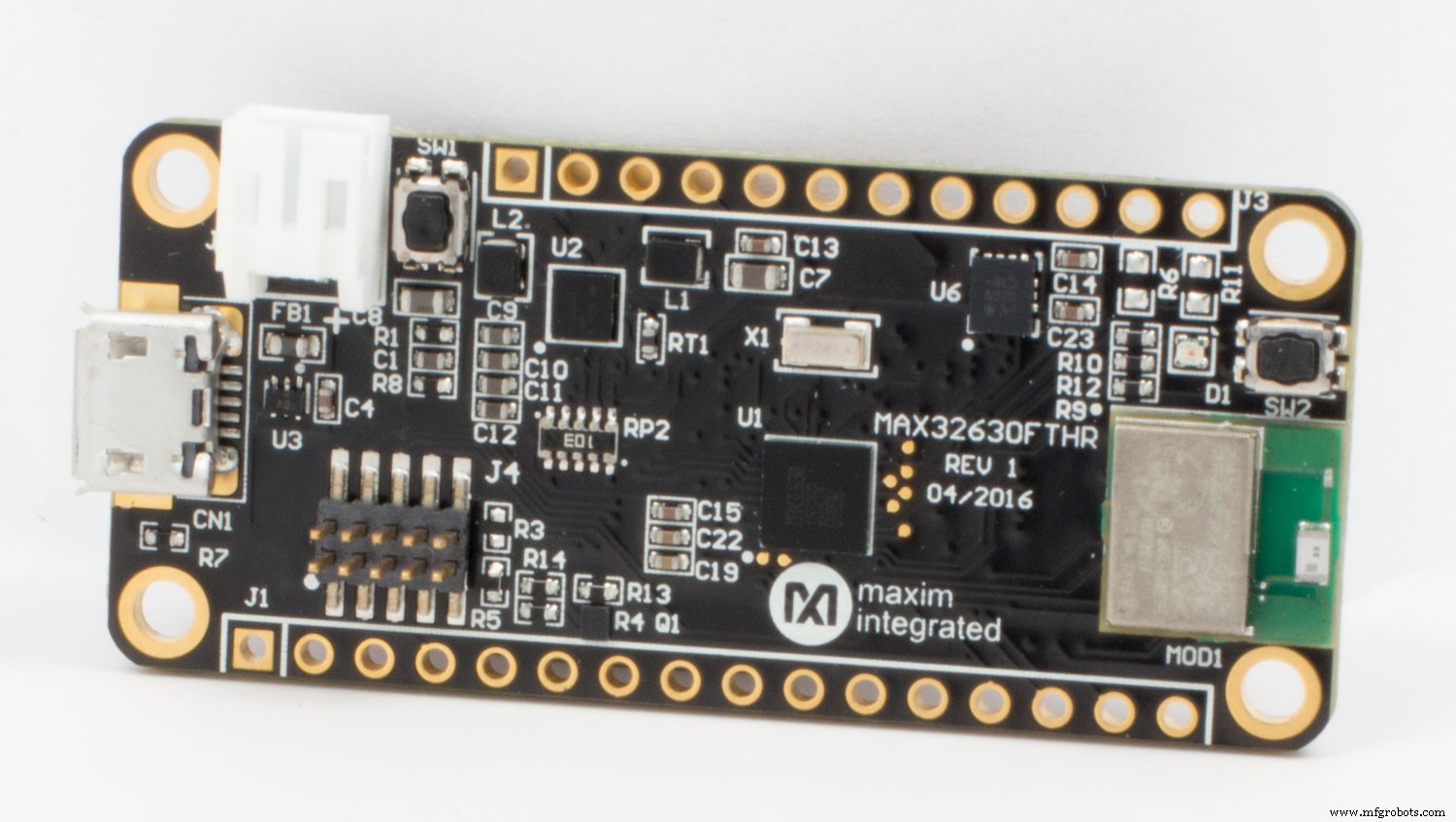
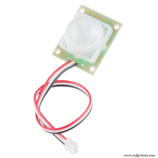
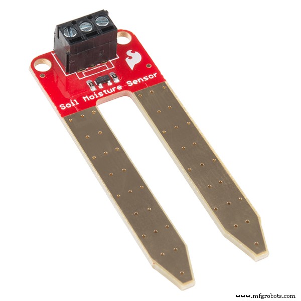
Ada banyak proyek otomatisasi IoT di luar sana, tapi percayalah tidak ada yang seperti ini! Octopoda dibuat menggunakan NodeMCU (MAX32620FTHR atau Arduino MKR 1010), Arduino Uno, dan Raspberry Pi 3 . Octopoda memungkinkan Anda membuat rumah Anda cerdas. Octopoda mengirimi Anda berbagai data seperti suhu , kelembaban, dan kualitas gas di dalam rumah/kantor/industri Anda. Octopoda mengirimkan pemberitahuan setiap kali mendeteksi segala jenis gerakan di dalam dan memberi tahu Anda kapan Anda perlu menyirami tanaman Anda . Anda juga dapat mengontrol peralatan melalui Blynk aplikasi di smartphone Anda. Octopoda bahkan mengaktifkan pencahayaan suasana hati yang sebenarnya!
Octopoda dilengkapi dengan kamera kecil mungil , yang mengirimi Anda umpan langsung . Kamera ini juga menggunakan kecerdasan buatan untuk mendeteksi manusia di depan mata dan mengirimkan foto mereka kepada Anda . Selain itu, fitur RFID penguncian pintu sistem ! Luar biasa, bukan?


Bagaimana Semuanya Bekerja?
NodeMCU terhubung ke banyak sensor, modul relai, dan LED RGB. Ini terhubung ke aplikasi Blynk di smartphone melalui WiFi, yang mengirimkan semua data dan memungkinkan Anda untuk mengontrol rumah Anda.
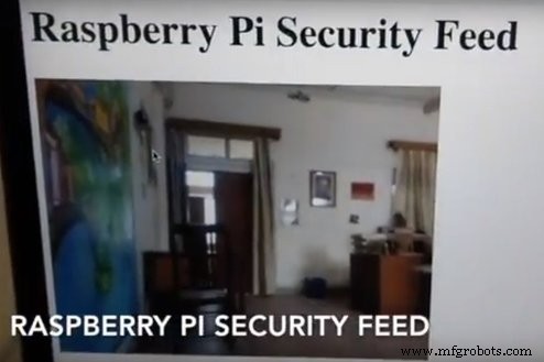
Raspberry Pi juga terhubung ke WiFi, yang memungkinkan Anda melihat umpan langsung melalui Kamera Pi. Kami juga telah menginstal pustaka OpenCV pada Pi, dan mengonfigurasi Pi untuk mendeteksi manusia mana pun yang terlihat dan mengirim email kepada Anda gambar mereka.
Unit pintu pintar menggunakan modul RFID. Ketika RFID yang diizinkan dibawa dalam jangkauannya, secara otomatis membuka pintu.
LANGKAH 1:Mengkodekan Octopoda Utama
Saya telah menambahkan komentar di hampir setiap baris, jadi Anda tidak hanya menyalin tetapi Anda mengerti. Di sini, saya akan memberi tahu Anda apa yang sebenarnya terjadi ketika kode dieksekusi secara singkat!
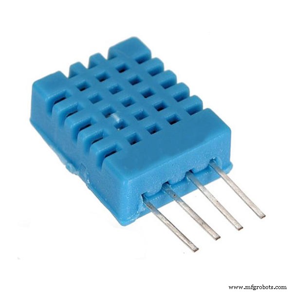
Kode ini menggunakan 2 library utama, yaitu Blynk Library untuk membuat kode tersebut kompatibel dengan Aplikasi Blynk dan library lainnya adalah DHT11 Temperature Library, yang mengubah data mentah dari sensor menjadi Temperatur dan Kelembaban. Untuk mengunduh perpustakaan ini, cukup buka tautan yang diberikan dalam kode dan unduh. Kemudian menuju ke Arduino IDE → Sketsa → Sertakan pustaka → Tambahkan pustaka .zip, dan pilih pustaka yang Anda unduh.
#include //Sertakan Blynk Library#include //Sertakan Blynk Library#include //Sertakan DHT sensor library#define BLYNK_PRINT Serial
Ini adalah beberapa kode Blynk yang membantu Anda menghubungkan nodemcu Anda ke internet dan kemudian mengautentikasinya ke aplikasi Anda.
// Anda harus mendapatkan Token Auth di Aplikasi Blynk.// Buka Pengaturan Proyek (ikon nut).char auth[] ="Kunci Auth Anda";// Kredensial WiFi Anda.// Setel kata sandi ke "" untuk jaringan yang terbuka.char ssid[] ="SSID WiFi Anda";char pass[] ="Pass WiFi Anda";
- Mendefinisikan Pin dan Bilangan Bulat:
Di segmen ini kami menentukan pin berbagai sensor kami. Anda dapat mengubahnya sesuai keyakinan Anda. Kami juga mendefinisikan beberapa bilangan bulat yang cenderung kami gunakan selama kode kami.
#define DHTPIN 2 // Sensor suhu dan kelembaban pin digital apa yang terhubung ke#define soilPin 4 // Pin digital apa yang terhubung dengan sensor kelembaban tanah#define gasPin A0 // Sensor gas pin analog apa yang terhubung to#define pirPin 12 // Pin digital apa sensor kelembaban tanah yang terhubung ke int pirValue; // Tempat untuk menyimpan read PIR Valueint soilValue; // Tempat penyimpanan baca Nilai Kelembaban Tanah di Nilai PIRpin; // Tempat untuk menyimpan nilai yang dikirim oleh Blynk App Pin V0int SOILpinValue; // Tempat untuk menyimpan nilai yang dikirim oleh Blynk App Pin V1
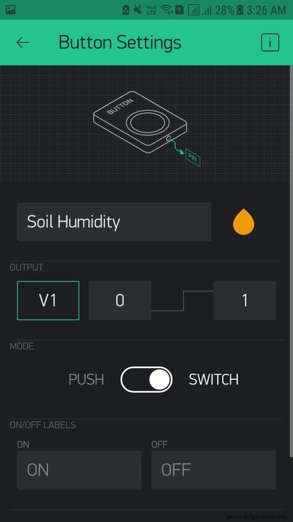
Dengan kode ini, kami memberi tahu aplikasi Blynk bahwa aplikasi ini dapat menggunakan Pin V0 dan Pin V1 untuk memberi tahu kode jika Deteksi Gerakan dan uji Kelembaban Tanah AKTIF.
BLYNK_WRITE(V0) //pin VO dari aplikasi Blynk memberi tahu apakah Deteksi Gerakan AKTIF{ PIRpinValue =param.asInt(); } BLYNK_WRITE(V1) //Pin V1 dari aplikasi Blynk memberi tahu apakah Kelembaban Tanah AKTIF{ SOILpinValue =param.asInt(); }
Kode ini mengambil data dari DHT11 membuatnya dapat digunakan, dan kemudian mengirimkannya ke Pin V5 dan V6 masing-masing.
void sendSensor(){ int h =dht.readHumidity(); int t =dht.readTemperature(); // atau dht.readTemperature(true) untuk Fahrenheit if (isnan(h) || isnan(t)) { Serial.println("Gagal membaca dari sensor DHT!"); // untuk memeriksa apakah sensor tidak mengirimkan nilai yang salah kembali; } // Anda dapat mengirim nilai apapun kapan saja. // Tolong jangan kirim lebih dari 10 nilai per detik. Blynk.virtualWrite(V5, h); // kirim kelembapan ke pin V5 Blynk.virtualWrite(V6, t); // kirim suhu ke pin V7}
- void getPirValue() &void getSoilValue() :
Membaca nilai digital dari sensor, kemudian menjalankan kondisi if-else untuk memeriksa status sensor. Jika sensor dalam kondisi yang diperlukan, itu akan mendorong pemberitahuan dari Aplikasi Blynk.
void getPirValue(void){ pirValue =digitalRead(pirPin); if (pirValue) //pin digital PIR memberikan nilai tinggi pada deteksi manusia { Serial.println("Gerakan terdeteksi"); Blynk.notify("Gerakan terdeteksi"); }}void getSoilValue(void){ soilValue =digitalRead(soilPin); if (Nilai Tanah ==TINGGI) //pin digital sensor tanah memberikan nilai rendah ketika kelembaban kurang { Serial.println("Tanaman Air"); Blynk.notify("Tanaman Air"); }}
Dalam pengaturan kami melakukan beberapa hal yang hanya dimaksudkan untuk dilakukan sekali. Seperti:Memulai komunikasi serial pada Baud Rate tetap, Otorisasi kode ini ke aplikasi Blynk, mulai pembacaan sensor Dht, lalu tweet ke pegangan twitter Anda bahwa Proyek Rumah Pintar Anda Online, lalu beri tahu node bahwa Pir Pin dan Sensor Tanah Pin dimaksudkan untuk mengambil Input saja.
pengaturan batal(){ // Debug konsol Serial.begin(9600); Blynk.begin(auth, ssid, pass); // Anda juga dapat menentukan server://Blynk.begin(auth, ssid, pass, "blynk-cloud.com", 8442); //Blynk.begin(auth, ssid, pass, IPAddress(192.168.1.100), 8442); dht.mulai(); // Memulai pembacaan DHT Blynk.tweet("OCTOPOD IS ONLINE! "); // Tweating di Twitter Anda Menangani bahwa Anda memproyeksikan pinMode online(pirPin,INPUT); // Mendefinisikan bahwa Pir Pin dimaksudkan untuk mengambil Input Only pinMode(soilPin,INPUT); // Mendefinisikan bahwa Pin Sensor Tanah dimaksudkan untuk mengambil Input Saja // Siapkan fungsi yang akan dipanggil setiap detik timer.setInterval(1000L, sendSensor);}
Dalam loop kita menulis hal-hal yang harus dilakukan berulang-ulang. Di sini, kami memastikan bahwa kode yang kami tulis sebelum penyiapan berjalan. Kemudian, kami menulis 2 Pernyataan If-Else yang memeriksa status Pin V0 dan Pin V1 dan kemudian mengambil nilai dari sensor yang sesuai.
void loop(){ Blynk.run(); timer.run(); if (PIRpinValue ==HIGH) // VO pin dari aplikasi Blynk memberi tahu apakah Deteksi Gerakan AKTIF { getPirValue(); } if (SOILpinValue ==HIGH) //V1 pin dari aplikasi Blynk memberi tahu apakah Soil Moisture ON { getSoilValue(); } }
LANGKAH 2:Mengkodekan Smart Lock RFID
Sejujurnya ini adalah Kode yang sederhana dan mudah dan tidak perlu banyak penjelasan. Tapi, saya masih akan memberi tahu Anda secara singkat apa fungsinya. Ada dua versi kode, satu adalah jika Anda ingin menghubungkan kotak unit pintu ke Bluetooth sehingga memberi tahu Anda ketika pintu Anda terbuka melalui terminal serial. Lainnya dikirim ke serial sehingga dapat dilihat jika Anda menghubungkan Arduino ke komputer Anda. Saya lebih suka yang sederhana tanpa versi Bluetooth sekalipun. Jadi ini dia!
- Buka Sketsa → Sertakan Perpustakaan → Kelola Perpustakaan → Ketik di bilah pencarian MFRC522 dan instal perpustakaan. Lalu buka File → Contoh → Perpustakaan Kustom → MFRC522 → dumpInfo Sketch. Di awal Anda dapat membaca cara menghubungkan pin (Atau lihat gambar). Kemudian jalankan kode dan buka serial monitor dan bawa satu Kartu Rfid Anda di depan Modul MFRC522 dan tunggu selama 5 detik. Kemudian, catat UID kartu dengan cara yang sama, catat UID kartu dan Gantungan Kunci Anda yang lain.
- Kemudian unduh kode yang Anda suka. Buka kode dan pergi ke baris ini. Di sini di tempat X ini tambahkan UID kartu yang ingin Anda gunakan untuk membuka pintu. Sekarang Anda siap, cukup unggah kodenya.
if (content.substring(1) =="XX XX XX XX") {}
Dalam kode ini ada dua hal utama yang kita lakukan, yaitu pada bagian If-Else dari kode tersebut. Dalam jika kita memberitahu arduino bahwa jika UID kartu cocok dengan UID tersebut membuat Servo bergerak (Agar Pintu Terbuka) dan berkedip beberapa Led dan membuat beberapa suara dengan menggunakan buzzer. Lain jika UID tidak membuat berkedip beberapa led dan membuat beberapa suara dengan menggunakan Buzzer.


LANGKAH 3:Pengaturan AI Deteksi Manusia Raspberry Pi
Dalam langkah yang dipandu ini kita akan belajar cara membuat Kamera Keamanan Cerdas. Kamera akan mengirimi Anda Email setiap kali mendeteksi objek dan Jika Anda berada di jaringan WiFi yang sama, Anda dapat mengakses rekaman langsung oleh kamera dengan mengetikkan alamat IP Raspberry Pi Anda. Saya akan menunjukkan cara membuat kamera pintar dari awal. Ayo pergi!
Persyaratan :
1. OpenCV (Perpustakaan Visi Komputer Sumber Terbuka)
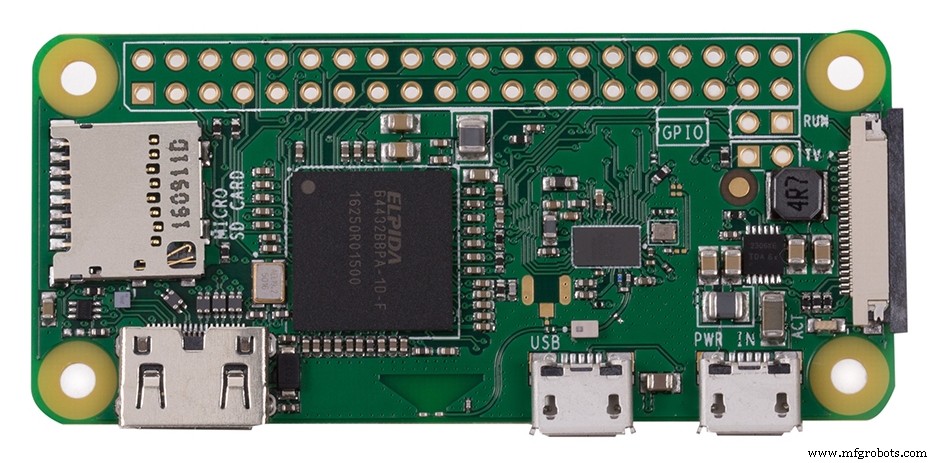
2. Raspberry Pi 3B
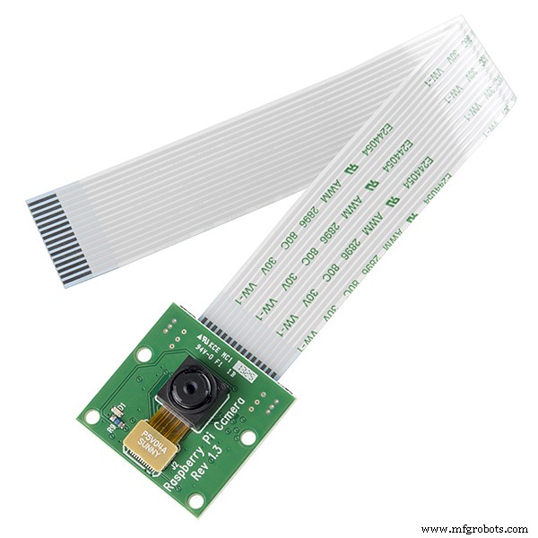
3. Kamera Raspberry Pi V2
Asumsi:
1. Raspberry Pi 3 dengan Raspbian Stretch diinstal. Jika Anda belum memiliki Raspbian Stretch OS, Anda perlu meningkatkan OS untuk memanfaatkan fitur baru Raspbian Stretch.
Untuk meningkatkan Raspberry Pi 3 Anda ke Raspbian Stretch, Anda dapat mengunduhnya di sini dan mengikuti petunjuk peningkatan ini (atau ini untuk rute NOOBS yang direkomendasikan untuk pemula).
Catatan:Jika Anda memutakhirkan Raspberry Pi 3 Anda dari Raspbian Jessie ke Raspbian Stretch, ada potensi masalah. Lanjutkan dengan risiko Anda sendiri, dan konsultasikan dengan forum Raspberry Pi untuk mendapatkan bantuan. Penting:Ini adalah rekomendasi saya agar Anda melanjutkan dengan instalasi baru Raspbian Stretch! Tidak disarankan untuk melakukan upgrade dari Raspbian Jessie.
2. Akses fisik ke Raspberry Pi 3 Anda sehingga Anda dapat membuka terminal dan menjalankan perintah Akses jarak jauh melalui SSH atau VNC. Saya akan melakukan sebagian besar tutorial ini melalui SSH, tetapi selama Anda memiliki akses ke terminal, Anda dapat dengan mudah mengikutinya.
- Langkah 1:MEMASANG KAMERA KE RASPBERRY PI 3
1. Buka modul Kamera Raspberry Pi Anda. Ketahuilah bahwa kamera dapat rusak oleh listrik statis. Sebelum mengeluarkan kamera dari tas anti-statis abu-abunya, pastikan Anda telah melepaskan diri dengan menyentuh benda yang diarde (misalnya radiator atau Sasis PC).
2. Instal modul Raspberry Pi Camera dengan cara memasukkan kabel ke dalam Raspberry Pi. Slot kabel ke dalam konektor yang terletak di antara port Ethernet dan HDMI, dengan konektor perak menghadap ke port HDMI.
3. Boot Raspberry Pi Anda.
4. Dari prompt, jalankan "Sudo raspi-config". Jika opsi "kamera" tidak terdaftar, Anda perlu menjalankan beberapa perintah untuk memperbarui Raspberry Pi Anda. Jalankan "sudo apt-get update" dan "sudo apt-get upgrade"
5. Jalankan "sudo raspi-config" lagi - Anda sekarang akan melihat opsi "kamera".
PERINTAH-
$ sudo raspi-config
6. Arahkan ke opsi "kamera", dan aktifkan (lihat di opsi antarmuka). Pilih "Selesai" dan reboot Raspberry Pi Anda atau cukup ketik berikut ini :
$ sudo reboot
- Langkah 2 :BUKA INSTALASI CV
Jika ini adalah pertama kalinya Anda menginstal OpenCV atau Anda baru memulai dengan Rasbian Stretch. Ini adalah tutorial yang sempurna untuk Anda.
Langkah #1:Perluas sistem file
Apakah Anda menggunakan instalasi baru Raspbian Stretch? Jika demikian, hal pertama yang harus Anda lakukan adalah memperluas sistem file Anda untuk memasukkan semua ruang yang tersedia di kartu micro-SD Anda:
PERINTAH-
$ sudo raspi-config
kemudian pilih item menu "Opsi Lanjutan" dan Diikuti dengan memilih "Perluas sistem file". Setelah diminta, Anda harus memilih opsi pertama, “A1. Perluas Sistem File", tekan Enter pada keyboard Anda, panah ke bawah ke tombol "", lalu reboot Pi Anda. Jika Anda menggunakan kartu 8GB, Anda mungkin menggunakan hampir 50% dari ruang yang tersedia, jadi satu hal sederhana yang harus dilakukan adalah menghapus mesin LibreOffice dan Wolfram untuk mengosongkan sebagian ruang di PI Anda:
PERINTAH-
$ sudo apt-get purge wolfram-engine $ sudo apt-get purge libreoffice* $ sudo apt-get clean$ sudo apt-get autoremove
Setelah menghapus Wolfram Engine dan LibreOffice, Anda dapat memperoleh kembali hampir 1GB!
Langkah #2: Instal dependensi
Ini bukan pertama kalinya saya membahas cara menginstal OpenCV di Raspberry Pi, jadi saya akan menyimpan instruksi ini di sisi yang lebih singkat, memungkinkan Anda untuk bekerja melalui proses instalasi:Saya juga menyertakan jumlah waktu dibutuhkan untuk mengeksekusi setiap perintah (beberapa tergantung pada kecepatan Internet Anda) sehingga Anda dapat merencanakan instalasi OpenCV + Raspberry Pi 3 Anda dengan tepat (OpenCV sendiri membutuhkan waktu sekitar 4 jam untuk dikompilasi — lebih lanjut tentang ini nanti). Langkah pertama adalah memperbarui dan meningkatkan paket yang ada:
PERINTAH-
$ sudo apt-get update &&sudo apt-get upgrade
Kami kemudian perlu menginstal beberapa alat pengembang, termasuk CMake, yang membantu kami mengonfigurasi proses pembuatan OpenCV:Raspbian Stretch:Instal OpenCV 3 + Python di Raspberry Pi Anda
PERINTAH-
$ sudo apt-get install build-essential cmake pkg-config
Selanjutnya, kita perlu menginstal beberapa paket I/O gambar yang memungkinkan kita memuat berbagai format file gambar dari disk. Contoh format file tersebut termasuk JPEG, PNG, TIFF, dll.:Raspbian Stretch
PERINTAH-
$ sudo apt-get install libjpeg-dev libtiff5-dev libjasper-dev libpng12-dev
Sama seperti kita membutuhkan paket I/O gambar, kita juga membutuhkan paket I/O video. Pustaka ini memungkinkan kita untuk membaca berbagai format file video dari disk serta bekerja secara langsung dengan aliran video
PERINTAH-
$ sudo apt-get install libavcodec-dev libavformat-dev libswscale-dev libv4l-dev $ sudo apt-get install libxvidcore-dev libx264-dev
Pustaka OpenCV hadir dengan sub-modul bernama highgui yang digunakan untuk menampilkan gambar ke layar kita dan membangun GUI dasar. Untuk mengkompilasi modul highgui, kita perlu menginstal pustaka pengembangan GTK:Raspbian Stretch:Instal OpenCV 3 + Python pada Raspberry Pi Anda
PERINTAH-
$ sudo apt-get install libgtk2.0-dev libgtk-3-dev
Banyak operasi di dalam OpenCV (yaitu operasi matriks) dapat dioptimalkan lebih lanjut dengan menginstal beberapa dependensi tambahan:
PERINTAH-
$ sudo apt-get install libatlas-base-dev gfortran
Pustaka pengoptimalan ini sangat penting untuk perangkat dengan sumber daya terbatas seperti Raspberry Pi. Terakhir, mari kita instal file header Python 2.7 dan Python 3 sehingga kita dapat mengkompilasi OpenCV dengan binding Python:Raspbian Stretch
PERINTAH-
$ sudo apt-get install python2.7-dev python3-dev
Jika Anda bekerja dengan instalasi baru OS, ada kemungkinan bahwa versi Python ini sudah berada di versi terbaru (Anda akan melihat pesan terminal yang menyatakan ini). Jika Anda melewatkan langkah ini, Anda mungkin melihat kesalahan terkait dengan file header Python.h tidak ditemukan saat menjalankan make to compile OpenCV. Langkah #3:Unduh kode sumber OpenCV
Langkah #3:Unduh OpenCV kode sumber
Sekarang setelah kita menginstal dependensi, mari ambil arsip 3.3.0 OpenCV dari repositori OpenCV resmi. Versi ini menyertakan modul dnn yang telah kita bahas pada posting sebelumnya di mana kita melakukan Deep Learning dengan OpenCV (Catatan:Karena versi openCV yang akan datang dirilis, Anda dapat mengganti 3.3.0 dengan nomor versi terbaru):
PERINTAH-
$ cd ~ $ wget -O opencv.zip https://github.com/Itseez/opencv/archive/3.3.0.zi...>> p$ unzip opencv.zip
Kami akan menginginkan penginstalan penuh OpenCV 3 (untuk memiliki akses ke fitur seperti SIFT dan SURF, misalnya), jadi kami juga perlu mengambil repositori opencv_contrib juga:Raspbian Stretch:Instal OpenCV 3 + Python pada Raspberry Pi Anda
PERINTAH-
$ wget -O opencv_contrib.zip https://github.com/Itseez/opencv_contrib/archive/...>>3.3.0$ unzip opencv_contrib.zip
Anda mungkin perlu memperluas perintah di atas menggunakan tombol “<=>” selama menyalin dan menempel. .zip di 3.3.0.zip mungkin tampak terpotong di beberapa browser. URL lengkap arsip OpenCV 3.3.0 adalah:https://github.com/Itseez/opencv_contrib/archive/... Catatan:Pastikan versi opencv dan opencv_contrib Anda sama (dalam hal ini, 3.3.0) . Jika nomor versi tidak cocok, kemungkinan Anda akan mengalami kesalahan waktu kompilasi atau runtime. Langkah #4:Python 2.7 atau Python 3? Sebelum kita dapat mulai mengkompilasi OpenCV pada Raspberry Pi 3 kita, pertama-tama kita perlu menginstal pip , pengelola paket Python
PERINTAH-
$ wget    https://bootstrap.pypa.io/get-pip.py>
>>
>$ sudo python get-pip.py $ sudo python3 get-pip.py
Anda mungkin mendapatkan pesan bahwa pip sudah diperbarui saat mengeluarkan perintah ini, tetapi sebaiknya jangan melewati langkah ini. Jika Anda sudah lama membaca PyImageSearch, Anda akan tahu bahwa saya adalah penggemar berat virtualenv dan virtualenvwrapper.
Menginstal paket-paket ini bukanlah persyaratan dan Anda benar-benar dapat menginstal OpenCV tanpa paket tersebut, namun demikian, saya sangat menyarankan Anda menginstalnya karena tutorial PyImageSearch lain yang ada (serta tutorial di masa mendatang) juga memanfaatkan lingkungan virtual Python.
Saya juga akan berasumsi bahwa Anda telah menginstal virtualenv dan virtualenvwrapper di sepanjang sisa panduan ini. Jadi, apa gunanya menggunakan virtualenv dan virtualenvwrapper ? Pertama, penting untuk dipahami bahwa lingkungan virtual adalah alat khusus yang digunakan untuk menjaga dependensi yang diperlukan oleh proyek yang berbeda di tempat yang terpisah dengan membuat lingkungan Python yang terisolasi dan independen untuk masing-masing proyek. Singkatnya, ini memecahkan dilema “Project X bergantung pada versi 1.x, tetapi Project Y membutuhkan 4.x”.
Ini juga menjaga paket situs global Anda tetap rapi, rapi, dan bebas dari kekacauan. Jika Anda ingin penjelasan lengkap tentang mengapa lingkungan virtual Python adalah praktik yang baik, bacalah posting blog yang luar biasa ini di RealPython. Ini adalah praktik standar dalam komunitas Python untuk menggunakan lingkungan virtual, jadi saya sangat menyarankan Anda melakukan hal yang sama:
PERINTAH-
$ sudo pip install virtualenv virtualenvwrapper$ sudo rm -rf ~/.cache/pip
Sekarang virtualenv dan virtualenvwrapper telah diinstal, kita perlu memperbarui file ~/.profile kita. sertakan baris berikut di bagian bawah file:Raspbian Stretch
PERINTAH-
$ nano ~/.profile
Salin &tempel baris baris berikut di bagian bawah file:
PERINTAH-
# virtualenv and virtualenvwrapperWORKON_HOME=$HOME/.virtualenvs source /usr/local/bin/virtualenvwrapper.sh
OR
You should simply use cat and output redirection to handle updating ~/.profile :
COMMAND-
$ echo -e "\n# virtualenv and virtualenvwrapper">> ~/.profile $ echo "exportWORKON_HOME=$HOME/.virtualenvs">> ~/.profile$ echo "source /usr/local/bin/virtualenvwrapper.sh">> ~/.profile
Now that we have our ~/.profile updated, we need to reload it to make sure the changes take affect. You can force a reload of your ~/.profile file by:Logging out and then logging back in.
Closing a terminal instance and opening up a new one
Or my personal favourite
COMMAND-
$ source ~/.profile
Note :I recommend running the source ~/.profile file each time you open up a new terminal to ensure your system variables have been setup correctly. Creating your Python virtual environment Next, let’s create the Python virtual environment that we’ll use for computer vision development:
COMMAND-
$ mkvirtualenv cv -p python2
This command will create a new Python virtual environment named cv using Python 2.7.
If you instead want to use Python 3, you’ll want to use this command instead:
COMMAND-
$ mkvirtualenv cv -p python3
Again, I can’t stress this point enough:the cv Python virtual environment is entirely independent and sequestered from the default Python version included in the download of Raspbian Stretch.
Any Python packages in the global site-packages directory will not be available to the cv virtual environment. Similarly, any Python packages installed in site-packages of cv will not be available to the global install of Python.
Keep this in mind when you’re working in your Python virtual environment and it will help avoid a lot of confusion and headaches. How to check if you’re in the “cv” virtual environment If you ever reboot your Raspberry Pi; log out and log back in; or open up a new terminal, you’ll need to use the workon command to re-access the cv virtual environment.
In previous blog posts, I’ve seen readers use the mkvirtualenv command — this is entirely unneeded! Themkvirtualenv command is meant to be executed only once:to actually create the virtual environment. After that, you can use workon and you’ll be dropped down into your virtual environment:
COMMAND-
$ source ~/.profile $ workon cv
To validate and ensure you are in the cv virtual environment, examine your command line — if you see the text (cv) preceding your prompt, then you are in the cv virtual environment:Make sure you see the “(cv)” text on your prompt, indicating that you are in the cv virtual environment.
Otherwise, if you do not see the (cv) text, then you are not in the cv virtual environment:
If you do not see the “(cv)” text on your prompt, then you are not in the cv virtual environment and need to run “source” and “workon” to resolve this issue. To fix this, simply execute the source and workon commands mentioned above. Installing NumPy on your Raspberry Pi Assuming you’ve made it this far, you should now be in the cv virtual environment (which you should stay in for the rest of this tutorial).
Step #4 :Installing NumPy on your Raspberry Pi
Our only Python dependency is NumPy, a Python package used for numerical processing:
COMMAND-
$ pip install numpy
the NumPy installation can take a bit of time.
Step #5:Compile and Install OpenCV
COMMAND-
$ workon cv
Once you have ensured you are in the cv virtual environment, we can setup our build using CMake:
COMMAND-
$ cd ~/opencv-3.3.0/ $ mkdir build $ cd build $ cmake -D CMAKE_BUILD_TYPE=RELEASE \ -D CMAKE_INSTALL_PREFIX=/usr/local \ -D INSTALL_PYTHON_EXAMPLES=ON \ -D OPENCV_EXTRA_MODULES_PATH=~/opencv_contrib-3.3.0/modules \ -D BUILD_EXAMPLES=ON ..
Now, before we move on to the actual compilation step, make sure you examine the output of CMake! Start by scrolling down the section titled Python 2 and Python 3 . If you are compiling OpenCV 3 for Python 2.7, then make sure your Python 2 section includes valid paths to the Interpreter, Libraries, numpy and packages
Checking that Python 3 will be used when compiling OpenCV 3 for Raspbian Stretch on the Raspberry Pi 3. Notice how the Interpreter points to our python2.7 binary located in the cv virtual environment. The numpy variable also points to the NumPy installation in the cv environment.
Again, the Interpreter points to our python3.5 binary located in the cv virtual environment while numpy points to our NumPy install.
In either case, if you do not see the cv virtual environment in these variables paths, it’s almost certainly because you are NOT in the cv virtual environment prior to running CMake! If this is the case, access the cv virtual environment using workon cv and re-run the cmake command outlined above.
Configure your swap space size before compiling Before you start the compile process, you should increase your swap space size. This enables OpenCV to compile with all four cores of the Raspberry PI without the compile hanging due to memory problems.
Open your /etc/dphys-swapfile and then edit the CONF_SWAPSIZE variable
COMMAND-
$ nano /etc/dphys-swapfile
and then edit the following section of the file:#set size to absolute value, leaving empty (default) then uses computed value # you most likely don't want this, unless you have an special disk situation
# CONF_SWAPSIZE=100 CONF_SWAPSIZE =1024
Notice that I’ve commented out the 100MB line and added a 1024MB line. This is the secret to getting compiling with multiple cores on the Raspbian Stretch. If you skip this step, OpenCV might not compile.
To activate the new swap space, restart the swap service:
COMMAND-
$ sudo /etc/init.d/dphys-swapfile stop
$ sudo /etc/init.d/dphys-swapfile start
Note:It is possible to burn out the Raspberry Pi microSD card because flash memory has a limited number of writes until the card won’t work. It is highly recommended that you change this setting back to the default when you are done compiling and testing the install (see below). To read more about swap sizes corrupting memory, see this page. Finally, we are now ready to compile OpenCV:
COMMAND-
$ make -j4
The -j4 switch stands for the number of cores to use when compiling OpenCV. Since we are using a Raspberry Pi 2, we’ll leverage all four cores of the processor for a faster compilation.
However, if your make command errors out, I would suggest starting the compilation over again and only using one core
$ make clean$ make
Once OpenCV 3 has finished compiling.Our OpenCV 3 compile on Raspbian Stretch has completed successfully.
From there, all you need to do is install OpenCV 3 on your Raspberry Pi 3:
COMMAND-
$ sudo make install$ sudo ldconfig
Step #6 :Finish installing OpenCV on your Pi
We’re almost done — just a few more steps to go and you’ll be ready to use your Raspberry Pi 3 with OpenCV 3 on Raspbian Stretch.
For Python 2.7:
#5 Provided your Step without error, OpenCV should now be installed in/usr/local/lib/python2.7/site-pacakges . You can verify this using the ls command:
COMMAND-
$ ls -l /usr/local/lib/python2.7/site-packages/ total 1852 -rw-r--r-- 1 root staff 1895772 Mar 20 20:00 cv2.so
Note:In some cases, OpenCV can be installed in /usr/local/lib/python2.7/dist-packages(note the dist-packages rather than site-packages ). If you do not find the cv2.so bindings insite-packages , we be sure to check dist-packages . Our final step is to sym-link the OpenCV bindings into our cv virtual environment for Python 2.7:
COMMAND-
$ cd ~/.virtualenvs/cv/lib/python2.7/site-packages/ $ ln -s /usr/local/lib/python2.7/site-packages/cv2.so cv2.so
For Python 3:After running make install , your OpenCV + Python bindings should be installed in/usr/local/lib/python3.5/site-packages . Again, you can verify this with the ls command:
COMMAND-
$ ls -l /usr/local/lib/python3.5/site-packages/ total 1852 -rw-r--r-- 1 root staff 1895932 Mar 20 21:51 cv2.cpython-34m.so
I honestly don’t know why, perhaps it’s a bug in the CMake script, but when compiling OpenCV 3 bindings for Python 3+, the output .so file is named cv2.cpython-35m-arm-linux-gnueabihf.so(or some variant of) rather than simply cv2.so (like in the Python 2.7 bindings). Again, I’m not sure exactly why this happens, but it’s an easy fix. All we need to do is rename the file:
COMMAND-
$ cd /usr/local/lib/python3.5/site-packages/ $ sudo mv cv2.cpython-35m-arm-linux-gnueabihf.so cv2.so
After renaming to cv2.so , we can sym-link our OpenCV bindings into the cv virtual environment
for Python 3.5:
COMMAND-
$ cd ~/.virtualenvs/cv/lib/python3.5/site-packages/ $ ln -s /usr/local/lib/python3.5/site-packages/cv2.so cv2.so
Step #7:Testing your OpenCV 3 install
Congratulations, you now have OpenCV 3 installed on your Raspberry Pi 3 running Raspbian Stretch! But before we pop the champagne and get drunk on our victory, let’s first verify that your OpenCV installation is working properly.
Open up a new terminal, execute the source and workon commands, and then finally attempt to import the Python + OpenCV bindings:
COMMAND-
$ source ~/.profile$ workon cv $ python>>> import cv2>>> cv2.__version__ '3.3.0'>>>
OpenCV 3 has been successfully installed on my Raspberry Pi 3 + Python 3.5 environment . Once OpenCV has been installed, you can remove both the opencv-3.3.0 and opencv_contrib-3.3.0 directories to free up a bunch of space on your disk:
COMMAND-
$ rm -rf opencv-3.3.0 opencv_contrib-3.3.0
However, be cautious with this command! Make sure OpenCV has been properly installed on your system before blowing away these directories. A mistake here could cost you hours in compile time.
Open your /etc/dphys-swapfile and then edit the CONF_SWAPSIZE variable COMMAND-
# set size to absolute value, leaving empty (default) then uses computed value# you most likely don't want this, unless you have an special disk situation CONF_SWAPSIZE=100 #CONF_SWAPSIZE=1024
Notice that I’ve commented out the 1024MB line and uncommented the 100MB line. As stated above, larger swap spaces may lead to memory corruption, so I recommend setting it back to 100MB. If you skip this step, your memory card won’t last as long. To revert to the smaller swap space, restart the swap service
COMMAND-
$ sudo /etc/init.d/dphys-swapfile stop
$ sudo /etc/init.d/dphys-swapfile start
- STEP 4:Setting Up Python Program
You can verify that the camera works by running.
COMMAND-
$ raspistill -o image.jpg
which will save a image from the camera in your current directory.
After you checked the camera is working. Now download all the python files and models from below link :
LINK:
https://drive.google.com/file/d/0B98uoD6BbkpqZU9FT...
You can open up the file inspector and view the image.
Make sure you are using the virtual environment by typing the following commands:
COMMANDS-
$ source ~/.profile $ workon cv
Next, navigate to the repository directory,
COMMANDS-
$ cd Smart-Security-Camera
and install the dependencies for the project
COMMANDS-
$ pip install -r requirements.txt
To get emails when objects are detected, you'll need to make a couple modifications to the mail.py file. Open mail.py with vim vim mail.py , then press i to edit. Scroll down to the following section
# Email you want to send the update from (only works with gmail)fromEmail ='[email protected]' fromEmailPassword ='password1234' # Email you want to send the update to toEmail ='[email protected]'
and replace with your own email/credentials.
The mail.py file logs into a gmail SMTP server and sends an email with an image of the object detected by the security camera. Press esc then ZZ to save and exit.
You can also modify the main.py file to change some other properties.
email_update_interval =600 # sends an email only once in this time intervalvideo_camera =VideoCamera(flip=True) # creates a camera object, flip verticallyobject_classifier =cv2.CascadeClassifier("models/fullbody_recognition_model.xml") # an opencv classifier facial_recognition_model.xml fullbody_recognition_model.xml upperbody_recognition_model.xml
Run the program python main.py
You can view a live stream by visiting the IP address of your pi in a browser on the same network. You can find the IP address of your Raspberry Pi by typing ifconfig in the terminal and looking for the inet address. Visit :5000 in your browser to view the stream.
Note:
To view the live stream on a different network than your Raspberry Pi, you can use ngrok to expose a local tunnel. Once downloaded, run ngrok with ./ngrok http 5000 and visit one of the generated links in your browser. Note:The video stream will not start automatically on startup. To start the video stream automatically, you will need to run the program from your /etc/rc.local file see this video for more information about how to configure that. Receiving Emails When receiving an email for the first time, you might get the following notification from Google:
By default, Google blocks apps from using SMTP without permissions. We can solve this by clicking on the allow "less secure apps" link and toggle the feature on. The next object detected will send an email.
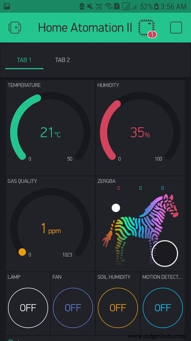
STEP 4:Blynk App Interface Setup
This is one of the easiest and fun steps. So let's get started. Shall we?
- Downloading the Blynk App is the first obvious step. Download it from App Store or Google Play Store. Sign Up or Login in the app to get started.
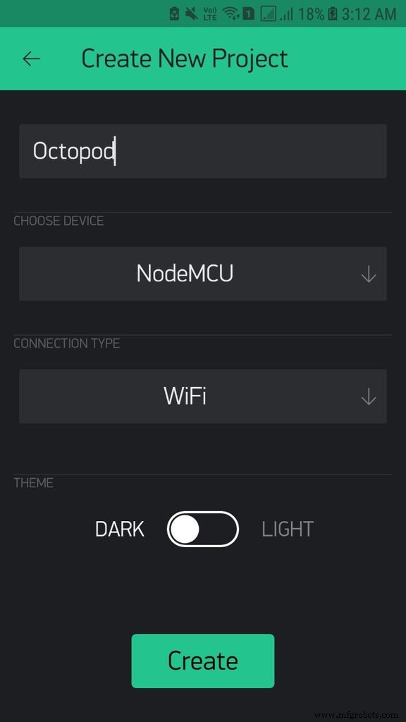
- Click on New Project to create a new project. Name it whatever you like. In devices Choose NodeMCU. In connection type choose WiFi and click on Create.
- Now you will get a Auth key on your Email. Make sure to copy that and add that to your code.
- Now click on the + sign to add widgets. You may need to buy some energy!
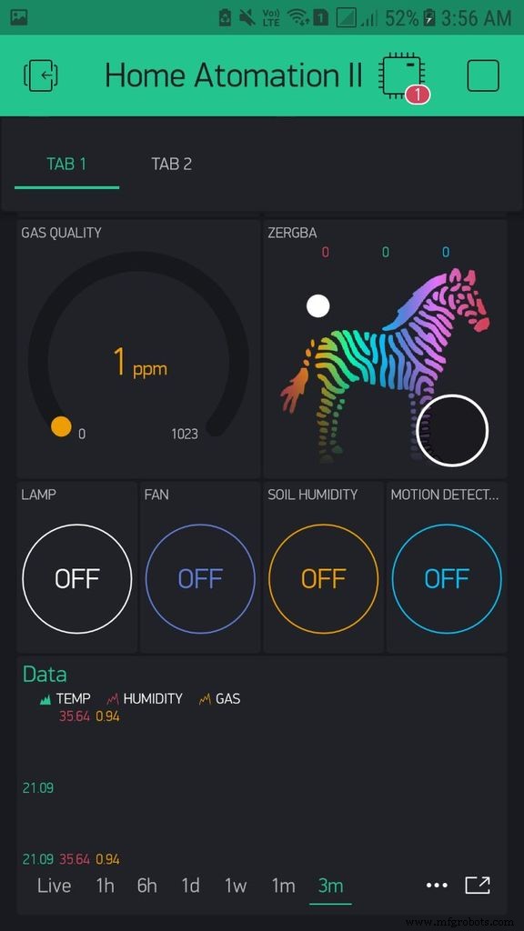
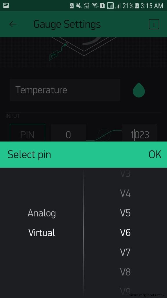
- Now add three Gauge's. Click on of the Gauge's, name it Temperature. Choose a color of you choice for this gauge. In the pin choose Virtual Pin V6. Set the range from 0 to 50 °C ( not sure for °F), make the label °C/ °F and keep the reading rate to Push.
- Repeat this for other two Gauges using data as shown in the pictures.
- Now, add a zeRGBa and set R to digital Pin GP15, B to GP3 and B to GP1.
- Now add 4 Buttons, change there colors accordingly. Set them as shown in the pictures.
- Add a SuperChart, add 3 data streams Temperature, Humidity and gas, set there colors, there pins, Range and Suffix.
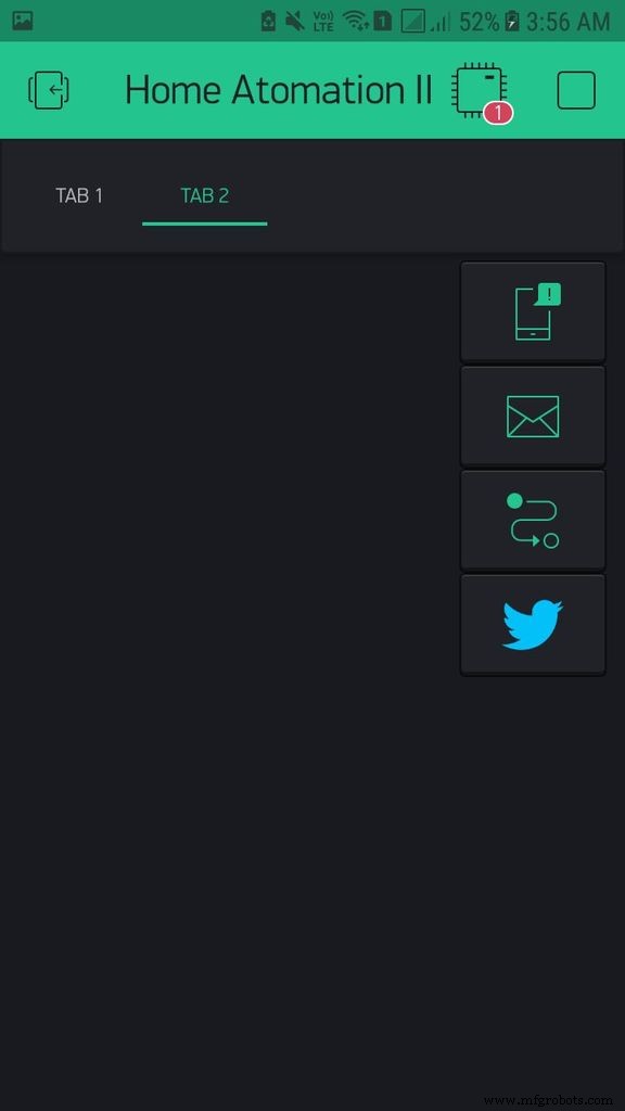
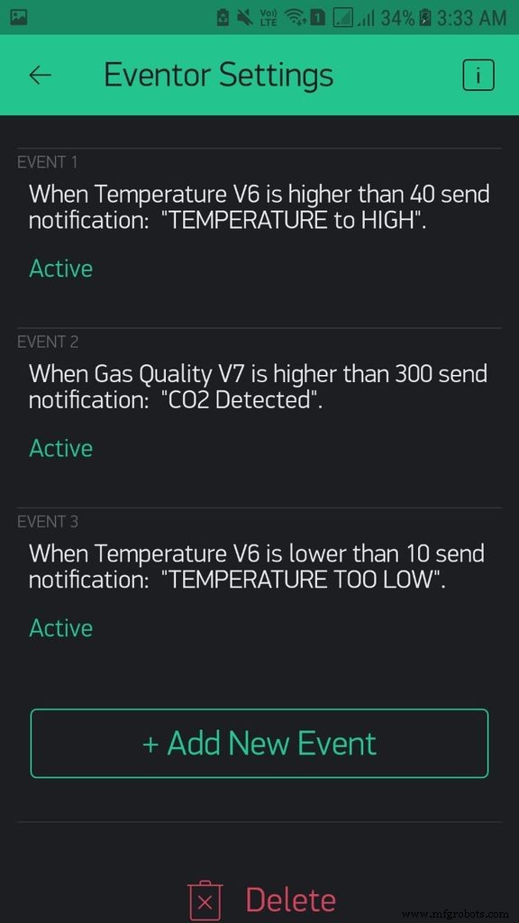
- Now, add tabs. Go to the second tab and add Twitter, Notifications, Email and Eventor. In Twitter add you twitter username and password. In Notifications, Switch on Notify when hardware goes off. In Email, set your Email address. In Eventor you can set many triggers, see the picture for the triggers that I have set up.
- You are done. now click on the play button to use the interface that you have created. You can change the interface as you like. It is really simple and fun process!
STEP 5:Making Octopod Structure
Warning - This is going to be one of most time-consuming process!
NOTE:You can skip this step and 3D print the enclosure that I have provided!
Actually, this step is optional yet the most important step! You can just take a shoe box and avoid all of this hard work. But on the contrary, this hard work makes the project unique. The idea for this unique design striked me while, I was doing my math homework. This shape is inspired from an octagon. Rather, This is a 3D octagon! So let's get started!
Making the Structure:
- Take your cardboard and draw a rectangle of 9 cm x 9.5 cm (You can change the dimensions as per your convince). Now, joining end to end draw 4 of theses similar rectangles (8 if your cardboard is long enough).
- Now make partial cuts (somewhat like paper creases) in between these rectangles and cut out this whole long piece. Repeat this process until you have 4 of these long pieces.
- Now, using a D draw a 135° and cut it out as shown in the images. Make 16 of these same angles.
- Using Glue gun glue these angles in between the small pieces. Repeat this for all the joints.
- Now using glue gun join 2 of these open structures to make a closed structure (somewhat octagon) .
- Now glue the other two open structure perpendicularly, making a 3-D shape.
- Now Cut 4 More pieces of of 9 x 9.5 cm and glue them in between all the empty spaces.
- Now you will be left with only 8 open triangles. Using Acrylic Butter paper cut 8 triangles, which will fit on these open areas, but don't glue them now.
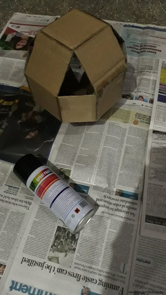
Paint Job:
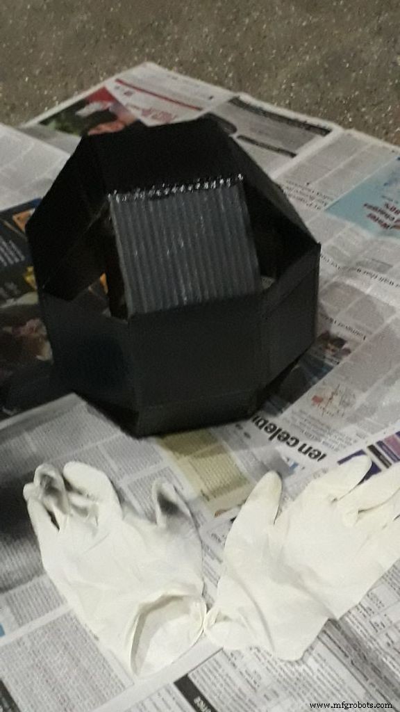
For this you need to head out towards an open area! Wear your Mask and Gloves and just make one coat over the structure that you have created. You can go to Youtube, to learn proper ways to make a perfect coat. Now let this dry for 4- 5 Hours and then apply 1 more coat. I think 3 coats will be good for this.
That's it! You have arrived with a unique piece of art.
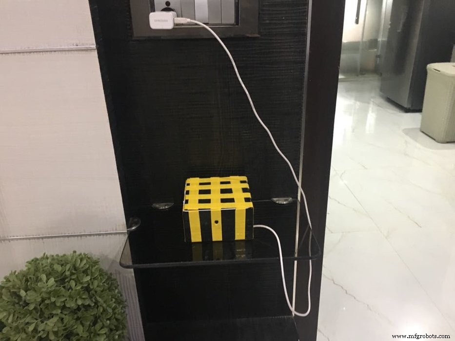
STEP 6:Making Door Lock Enclosure
Really simple. Just take a Shoe Box and apply 2- 3 even coats of spray. And maybe for design make check pattern using duck tape like we did!
STEP 7:Assembling the Octopod
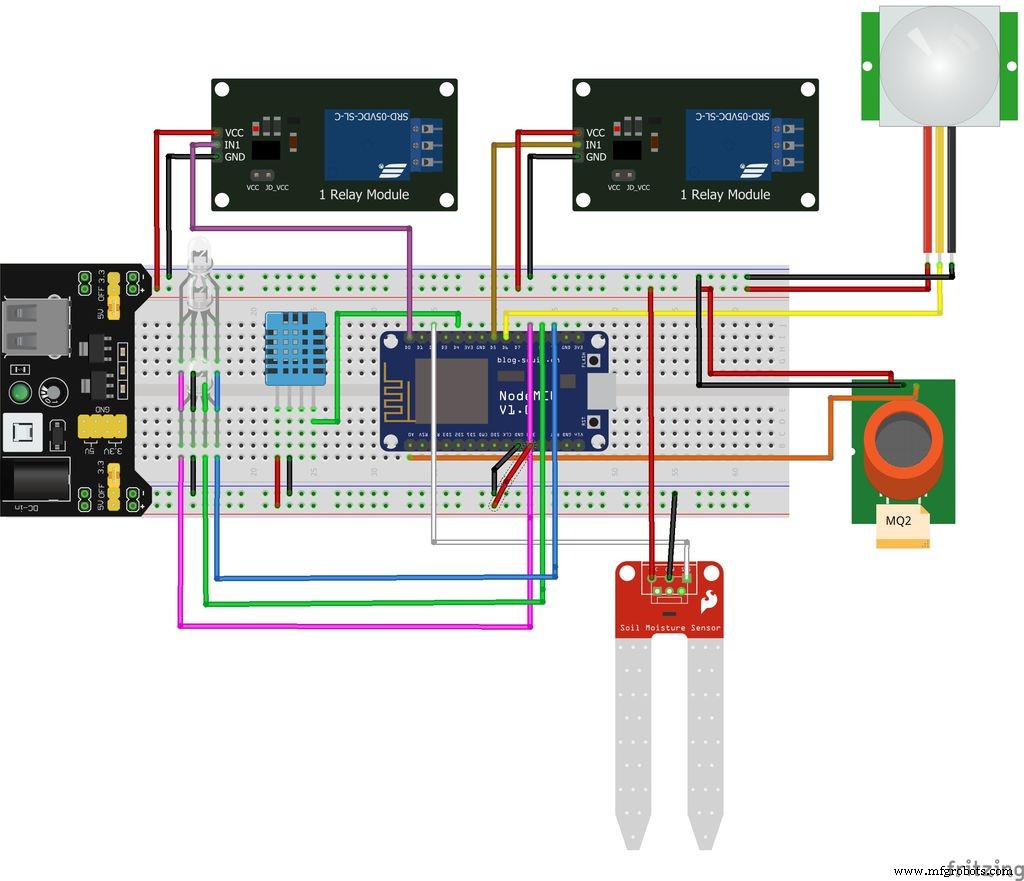
I have tried to make this step as simple as possible, by making the schematic diagram. Refer the picture or the file, and make connections accordingly. I will briefly explain all the connections!
- We have connected the nodeMCU to a large size Solderless Breadboard. We have also connected Breadboard power supply on the breadboard. NodeMCU, all the sensors, LED's and other components are powered by the power supply.
- Following are the sensor connections:DHT11 → D4 / GP2 MQ2 → A0 / adc00 Soil Moisture Sensor → D2 / GP4 PIR → D6 / GP1 RGB R → D8 / GP15, G → Rx / GP3, B → Tx / GP1 RelayLn1 → D0 / GP16, Ln2 → D5 / GP14 Make the following connections.
- For powering this you can use Power Bank or a Wall Adapter, which will be connected to the breadboard Power supply.
- Now, take your Raspberry Pi along with the Raspberry Pi Camera. Make a small hole in one of the walls of the cardboard and glue or tape your Raspberry Camera.
Now, insert all these electronics inside, through any open triangle and close the triangle by using the cut outs of acrylic butter paper that we made. It is better to leave 1 or 2 open, in case something inside needs to be fixed! Also let the prongs of the Soil Moisture Sensor sit outside.
All done! We have completed the making process of the Octopod! Now, Just switch On the power and keep your Octopod over the dining Table or maybe on the Guest's Table and enjoy! To see the live feed from the Raspberry Pi, just open a browser and put in the IP address of the Pi. Enjoy!

STEP 8:Assembling the Door Lock
After uploading the code on your Arduino just make the connections as shown in the picture or in fritzing file! It is quite simple. Then take the handy shoe box that we made make 2 holes in it for the LED's to pop out. and allow the servo to stand out. These days mechanical locks like servo's are also available in the market, though servo works just as fine. This is just an experiment, so please so please don't use this as you actual lock! Glue the Rfid to one wall of the box and also glue the small breadboard and Arduino. You can use a wall adapter or a Power bank to power this. Just power the Arduino and you will be good to go! Done!
CONCLUSION:
This was a really fun project to do!
I was really happy how it turned out. I think the lights look really well, and i think its well worth making even one of these as a side lamp. I really can't thank creators of Blynk and OpenCV libraries enough, they are both really excellent pieces of software and made this project possible! As always, if you have any questions on any part of the process please let me know and I will be happy to try help. Thanks a lot! And Please Vote for Us!
-Saksham
Arduino Blog
Full Instructable

UPDATE:
I have been working on integrating this system with Amazon Alexa, I am almost done. Will upload the code in 2-3 days!
Kode
- octopod.ino
- octopod_door.ino
- octopod_door_bluetooth.ino
octopod.inoArduino
This is the main code for Arduino MKR 1010 (NodeMCU in my case)
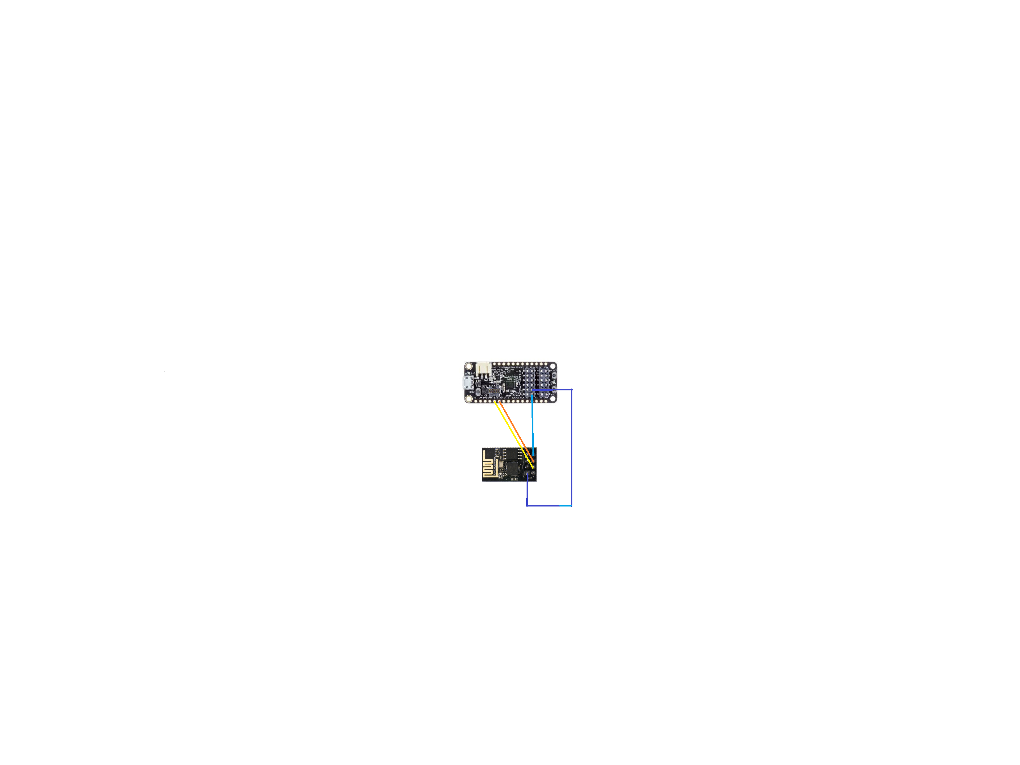
If you are using MAX32620FTHR, download libraries for it. Then change the board in board settings. Also change the pin as given bellow
ESP MAX
AO - - - - - - - - - - - - GPIO2
A1 - - - - - - - - - - - - - GPIO1
Soil Sensor MAX
analog sensor - - - GPIO3
Gas Sensor (MQ2) MAX
sensor - - - - - - - - - - - GPIO4
PIR Sensor MAX
sensor - - - - - - - - - - - -GPIO0
Relay MAX
1 - - - - - - - - - - - - - - - - - M0
2 - - - - - - - - - - - - - - - - - M1/*************************************************************************** OCTOPOD:A SMART HOME AUTOMATION PROJECT MADE BY SAKSHAM Download latest Blynk library here:https://github.com/blynkkk/blynk-library/releases/latestDownload latest DHT Sensor library here:https://github.com/adafruit/DHT-sensor-library***************************************************************************/#include //Include ESP8266 Wifi Library#include //Include Blynk Library#include //Include DHT sensor library#define BLYNK_PRINT Serial// You should get Auth Token in the Blynk App.// Go to the Project Settings (nut icon).char auth[] ="Your Blynk Auth Key";// Your WiFi credentials.// Set password to "" for open networks.char ssid[] ="Your WiFi SSID";char pass[] ="Your WiFi Password";#define DHTPIN 2 // What digital pin temperature and humidity sensor is connected to#define soilPin 4 // What digital pin soil moisture sensor is connected to#define gasPin A0 // What analog pin gas sensor is connected to#define pirPin 12 // What digital pin soil moisture sensor is connected to int pirValue; // Place to store read PIR Valueint soilValue; // Place to store read Soil Moisture Valueint PIRpinValue; // Place to store the value sent by Blynk App Pin V0int SOILpinValue; // Place to store the value sent by Blynk App Pin V1// Uncomment whatever type you're using!#define DHTTYPE DHT11 // DHT 11//#define DHTTYPE DHT22 // DHT 22, AM2302, AM2321//#define DHTTYPE DHT21 // DHT 21, AM2301DHT dht(DHTPIN, DHTTYPE);BlynkTimer timer;// This function sends Arduino's up time every second to Virtual Pin (5).// In the app, Widget's reading frequency should be set to PUSH. This means// that you define how often to send data to Blynk App.BLYNK_WRITE(V0) //VO pin from Blynk app tells if Motion Detection is ON{ PIRpinValue =param.asInt(); } BLYNK_WRITE(V1) //V1 pin from Blynk app tells if Soil Moisture is ON{ SOILpinValue =param.asInt(); } void sendSensor(){ int h =dht.readHumidity(); int t =dht.readTemperature(); // or dht.readTemperature(true) for Fahrenheit if (isnan(h) || isnan(t)) { Serial.println("Failed to read from DHT sensor!"); // to check if sensor is not sending any false values return; } // You can send any value at any time. // Please don't send more that 10 values per second. Blynk.virtualWrite(V5, h); // send humidity to pin V5 Blynk.virtualWrite(V6, t); // send temperature to pin V7}void getPirValue(void){ pirValue =digitalRead(pirPin); if (pirValue) //digital pin of PIR gives high value on human detection { Serial.println("Motion detected"); Blynk.notify("Motion detected"); }}void getSoilValue(void){ soilValue =digitalRead(soilPin); if (soilValue ==HIGH) //digital pin of soil sensor give low value when humidity is less { Serial.println("Water Plants"); Blynk.notify("Water Plants"); }}void setup(){ // Debug console Serial.begin(9600); Blynk.begin(auth, ssid, pass); // You can also specify server://Blynk.begin(auth, ssid, pass, "blynk-cloud.com", 8442); //Blynk.begin(auth, ssid, pass, IPAddress(192,168,1,100), 8442); dht.begin(); // Begins DHT reading Blynk.tweet("OCTOPOD IS ONLINE! "); // Tweating on your Twitter Handle that you project is online pinMode(pirPin,INPUT); // Defining that Pir Pin is meant to take Input Only pinMode(soilPin,INPUT); // Defining that Soil Sensor Pin is meant to take Input Only // Setup a function to be called every second timer.setInterval(1000L, sendSensor);}void loop(){ Blynk.run(); timer.run(); if (PIRpinValue ==HIGH) //VO pin from Blynk app tells if Motion Detection is ON { getPirValue(); } if (SOILpinValue ==HIGH) //V1 pin from Blynk app tells if Soil Moisture is ON { getSoilValue(); } }
octopod_door.inoArduino
Code for Automatic Door Lock Control (NO BLUETOOTH VERSION)/*********************************************************************************************************** OCTOPOD:A SMART HOME AUTOMATION PROJECT MADE BY SAKSHAM ARDUINO RFID DOOR LOCK CODELibrary Required - MFRC522 ************************************************************************************************************/#include #include #include #define SS_PIN 10#define RST_PIN 9#define LED_G 5 //define green LED pin#define LED_R 4 //define red LED#define BUZZER 2 //buzzer pinMFRC522 mfrc522(SS_PIN, RST_PIN); // Create MFRC522 instance.Servo myServo; //define servo name void setup() { Serial.begin(9600); // Initiate a serial communication SPI.begin(); // Initiate SPI bus mfrc522.PCD_Init(); // Initiate MFRC522 myServo.attach(3); //servo pin myServo.write(0); //servo start position pinMode(LED_G, OUTPUT); pinMode(LED_R, OUTPUT); pinMode(BUZZER, OUTPUT); noTone(BUZZER); Serial.println("Put your card to the reader..."); Serial.println();}void loop() { // Look for new cards if ( ! mfrc522.PICC_IsNewCardPresent()) { return; } // Select one of the cards if ( ! mfrc522.PICC_ReadCardSerial()) { return; } //Show UID on serial monitor Serial.print("UID tag :"); String content=""; byte letter; for (byte i =0; i octopod_door_bluetooth.inoArduino
Code for Automatic Door Lock Control (Bluetooth Version)/*********************************************************************************************************** OCTOPOD:A SMART HOME AUTOMATION PROJECT MADE BY SAKSHAM ARDUINO RFID DOOR LOCK CODELibrary Required - MFRC522 ************************************************************************************************************/#include SoftwareSerial BTserial(0, 1); // RX | TX#include #include #include #define SS_PIN 10#define RST_PIN 9#define LED_G 5 //define green LED pin#define LED_R 4 //define red LED#define BUZZER 2 //buzzer pinMFRC522 mfrc522(SS_PIN, RST_PIN); // Create MFRC522 instance.Servo myServo; //define servo namevoid setup(){ BTserial.begin(9600); // Initiate a serial communication BTserial.println("Waiting for connections..."); SPI.begin(); // Initiate SPI bus mfrc522.PCD_Init(); // Initiate MFRC522 myServo.attach(3); //servo pin myServo.write(0); //servo start position pinMode(LED_G, OUTPUT); pinMode(LED_R, OUTPUT); pinMode(BUZZER, OUTPUT); noTone(BUZZER); BTserial.println("Put your card to the reader..."); BTserial.println();}void loop(){ // Look for new cards if ( ! mfrc522.PICC_IsNewCardPresent()) { return; } // Select one of the cards if ( ! mfrc522.PICC_ReadCardSerial()) { return; } //Show UID on serial monitor BTserial.print("UID tag :"); String content =""; byte letter; for (byte i =0; i Suku cadang dan penutup khusus
This is the basic design that you can use if you want to make the enclosure out of Cardboard/ Wood like me! octopod_v2_ukTmIJ0uMl.f3dProper Enclosure that you can 3D Print! octo_2_v3_sii4tuCF7d.f3d Skema
Pin configuration might be different with Arduino MKR 1010 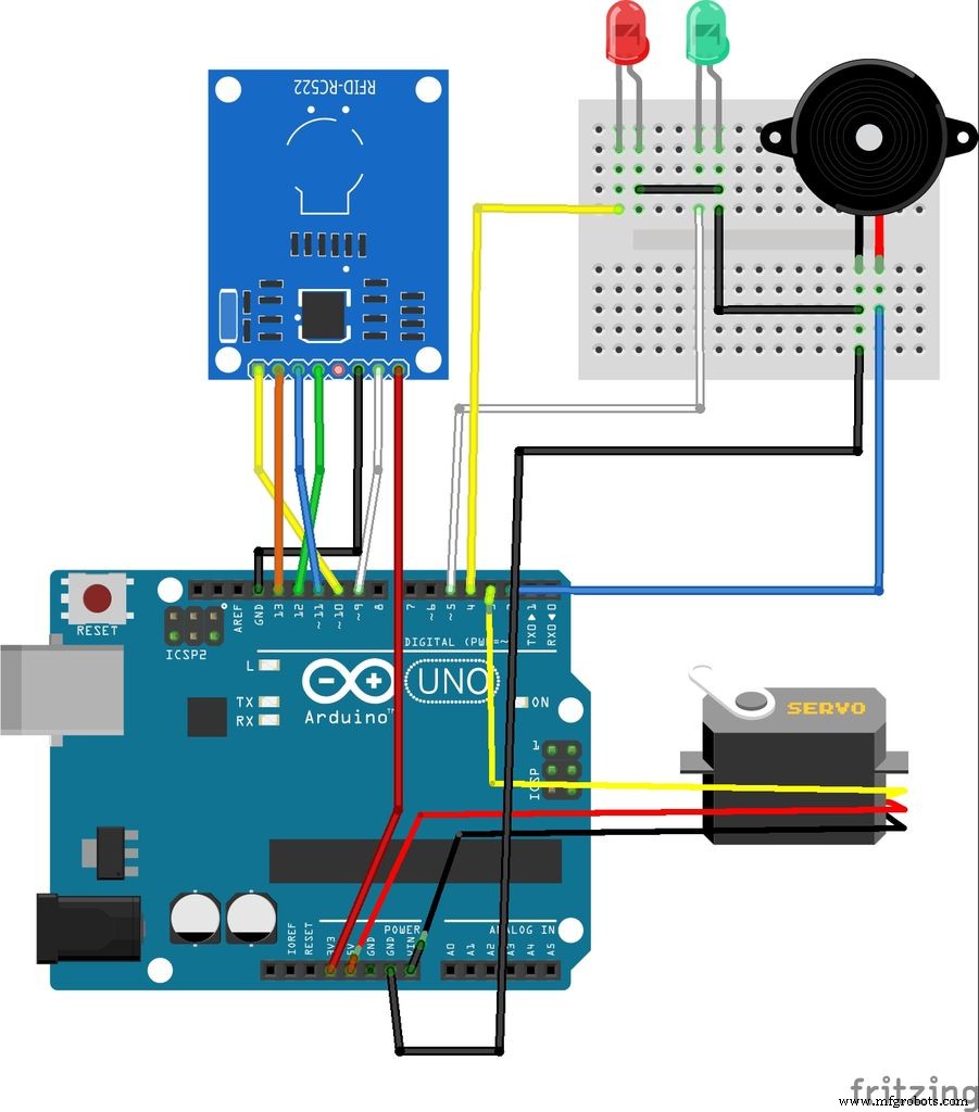 Without Bluetooth
For Bluetooth connect Rx (HC-05) --> Tx (Arduino)
Tx (HC-05) --> Rx (Arduino)
and 5v to 5v
Ground to Ground ESP MAX
AO - - - - - - - - - - - - GPIO2
A1 - - - - - - - - - - - - - GPIO1
Soil Sensor MAX
analog sensor - - - GPIO3
Gas Sensor (MQ2) MAX
sensor - - - - - - - - - - - GPIO4
PIR Sensor MAX
sensor - - - - - - - - - - - -GPIO0
Relay MAX
1 - - - - - - - - - - - - - - - - - M0
2 - - - - - - - - - - - - - - - - - M1