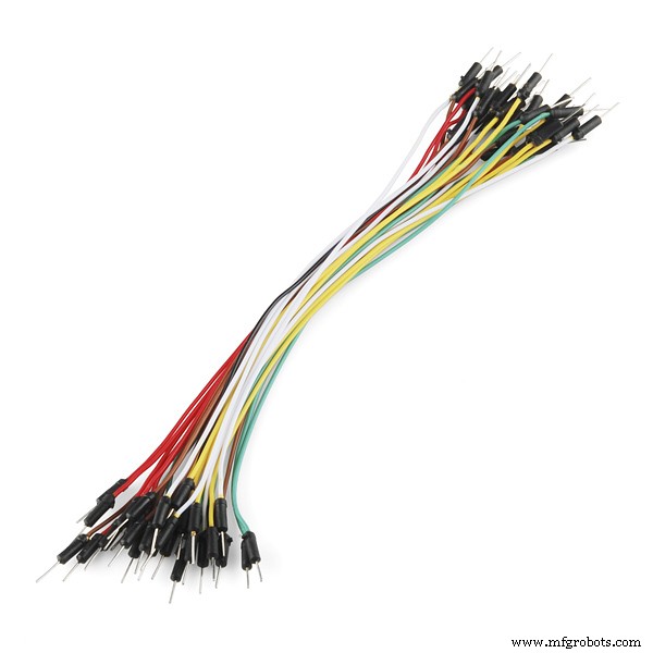
Hari ini, kami akan membangun perangkat yang terhubung ke internet dan memungkinkan pengguna untuk mengontrol rumahnya dari jarak jauh melalui wifi. kami akan menggunakan papan Arduino (model apa pun akan melakukan pekerjaan dengan baik) dengan modul wifi ESP8266-01 untuk membuat perangkat ini. Mari kita mulai!
Apa itu rumah pintar?
Skenario Kerja
Panel Kontrol
Kami akan membangun halaman web sederhana yang akan berfungsi sebagai panel kontrol untuk memungkinkan pengguna mengontrol peralatan rumah apa pun yang terhubung ke sistem kami. Untuk membangun halaman web kita akan menggunakan:
HTML
CSS
Jquery
Perangkat Keras Tertanam
halaman web mengirimkan beberapa perintah ke ESP8266-01 yang berfungsi sebagai server web yang terhubung ke papan Arduino. Dan sesuai dengan data yang masuk, board Arduino akan melakukan beberapa tindakan seperti menyalakan bohlam, mematikan TV dan pada bagian ini kita akan menggunakan:
Arduino
ESP8266-01
Memulai dengan ESP8266-01
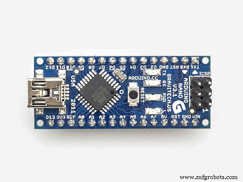
Seperti yang kami nyatakan sebelumnya, kami membutuhkan papan Arduino kami untuk terhubung ke Internet tetapi Arduino Nano versi yang kami gunakan saat ini tidak memiliki fitur itu. Jadi, kita akan menggunakan modul wifi ESP8266-01 untuk menambahkan fitur wifi ke papan Arduino kecil kita.
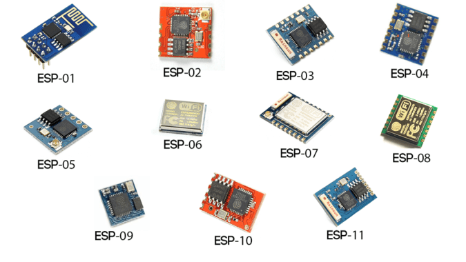
ada banyak model modul wifi ESP di luar sana, mana yang harus saya pilih?! Yah, hampir semua modul wifi keluarga ESP di luar sana akan melakukan pekerjaan dengan baik tetapi masing-masing memiliki fitur dan spesifikasinya sendiri. Saya mendorong Anda untuk melihat masing-masing spesifikasi dan fitur untuk memilih yang paling sesuai dengan kebutuhan Anda.
Sesuai dengan kebutuhan saya, saya menemukan ESP8266-01 adalah yang paling cocok dan itu karena berbagai alasan. Ini sangat terkenal di komunitas pembuat. Hasilnya, ia mendapatkan komunitas online yang sangat solid sehingga Anda dapat menemukan jawaban untuk hampir semua pertanyaan atau masalah yang Anda hadapi dengan modul kecil yang mengagumkan ini. Juga, harganya sangat murah (sekitar 1,5$).
Juga, sangat mudah digunakan dengan papan Arduino karena ini adalah modul wifi Serial yang dapat berkomunikasi dengan papan Arduino melalui komunikasi serial. Ini memiliki Mikrokontroler built-in yang berarti Anda dapat menggunakannya sebagai mikrokontroler mandiri dan modul wifi dalam satu kombo yang sangat keren. Ini memiliki dua GPIO bawaan. Hanya dengan 1,5$, Anda akan mendapatkan semua fitur ini yang sangat keren, sebenarnya. Mari kita lihat lebih dekat modul ini.
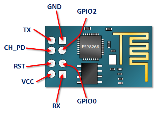
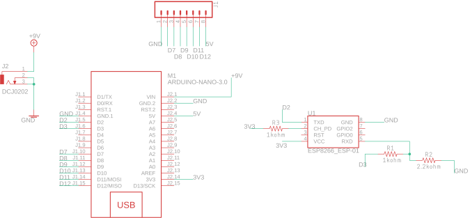
Pinout ESP8266-01
VCC: sambungkan ke sumber daya +3.3V. jangan hubungkan dengan sumber 5V nanti rusak .
GND: -ve pin, sambungkan ke ground sirkuit Anda.
CH_PD: chip mengaktifkan pin – Aktif TINGGI. hubungkan ke nilai logika HIGH untuk memungkinkan modul melakukan booting.
RST: Pin Reset Chip – Aktif LOW, ketika ditarik LOW akan Reset modul.
GPIO0, GPIO2: Pin input/output tujuan umum.
Terima kasih: sambungkan ke Rx mikrokontroler (Arduino) untuk membangun komunikasi serial.
Rx: sambungkan ke Tx mikrokontroler (Arduino) untuk membangun komunikasi serial.
Konfigurasi ESP8266-01
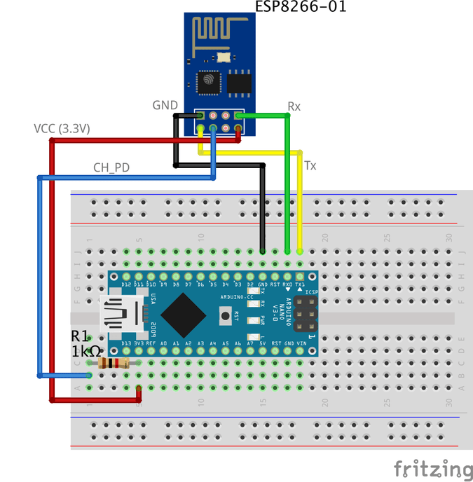
Seperti yang kami nyatakan sebelumnya modul ESP8266-01 berkomunikasi dengan papan Arduino melalui komunikasi Serial, yang berarti bahwa kita perlu menghubungkannya dengan pin Serial Arduino 0, 1(Tx, Rx). Tapi masalahnya di sini adalah pin ini akan sibuk karena kita akan menggunakan monitor Arduino Serial bersama ESP8266-01 untuk keperluan debugging. Jadi, kita perlu mencari dua pin komunikasi Serial lainnya untuk menggunakannya dengan ESP8266-01.
Untungnya, Arduino membuat ini mudah. Ada perpustakaan yang disebut "SoftwareSerial" yang dikembangkan untuk memungkinkan komunikasi serial pada pin digital Arduino lainnya, menggunakan perangkat lunak untuk mereplikasi fungsinya. Misalnya, dengan menggunakan library ini saya dapat mengatur pin 2, 3 (SoftwareSerial) sebagai Rx dan Tx di samping pin 0, 1 (Hardware Serial).
“Serial Perangkat Lunak” perpustakaan bekerja dengan baik selama kecepatan transmisi kurang dari 19.200 baud. Tapi, ada masalah kecil di sini! modul wifi ESP8266-01 berasal dari pabrik yang diprogram untuk berkomunikasi pada kecepatan 115.200 baud yang entah bagaimana sulit di perpustakaan "SoftwareSerial" untuk berkomunikasi. Jadi, kita perlu memprogram ulang modul wifi kita untuk mengatur kecepatan komunikasi ke 9600 baud yang bekerja cukup baik dengan perpustakaan "SoftwareSerial". Untuk melakukannya kita akan menggunakan beberapa “AT Commands”.
Mengubah kecepatan komunikasi ESP8266-01
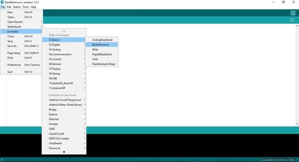
Langkah pertama:Unggah program kosong ke papan Arduino
Pada langkah ini, kami mengunggah kode kosong ke papan Arduino. Hanya untuk memastikan bahwa tidak ada yang dieksekusi di latar belakang oleh papan Arduino.
Langkah Kedua:Menghubungkan ESP8266-01 dengan papan Arduino
Untuk mengkonfigurasi ulang ESP8266-01 dan mengubah kecepatan komunikasi (baud rate) kami menggunakan AT-commands. Secara sederhana, perintah AT adalah beberapa instruksi yang digunakan untuk mengontrol modem, ponsel, modul Bluetooth, modul wifi, Modul GSM.
dengan perintah ini kita bisa mendapatkan informasi dasar tentang ponsel kita atau Modul GSM seperti nama pabrikan, nomor model, IMEI dan sebagainya. “AT” adalah singkatan dari “ATtention” dan disebut AT-commands karena setiap perintah dimulai dengan "AT". awalan “AT” bukan merupakan bagian dari perintah itu sendiri, itu hanya memberi tahu modul awal dari perintah.
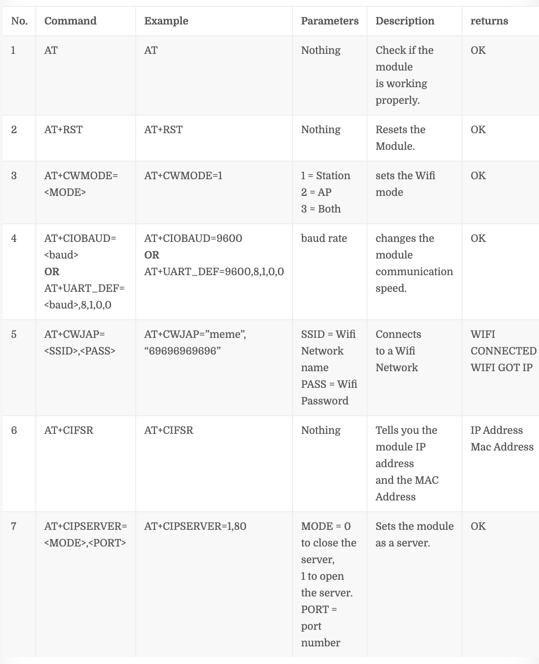
Beberapa Perintah AT Penting
Nomor perintah “4” tergantung pada versi firmware ESP8266-01 Anda, jika perintah ini tidak bekerja dengan Anda AT+CIOBAUD= Coba yang ini AT+UART_DEF=,8,1,0,0
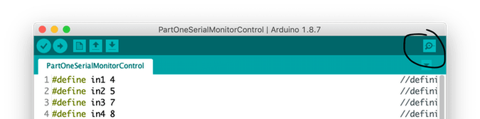
Langkah 1:Buka Serial Monitor
Langkah 2:Atur kecepatan Komunikasi ke 115.200 baud
Seperti yang kami nyatakan sebelumnya, ESP berasal dari pabrikan yang diprogram untuk berkomunikasi pada kecepatan 115.200 baud. Jadi kita perlu mengatur kecepatan komunikasi Arduino ke 115, 200 juga untuk pertama kalinya baru kemudian kami akan mengubahnya nanti. Selain itu, Anda harus memilih “Baik NL &CR” .
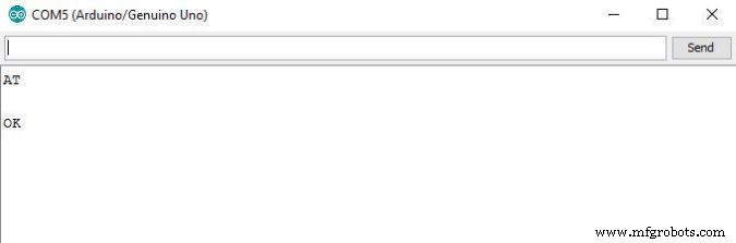
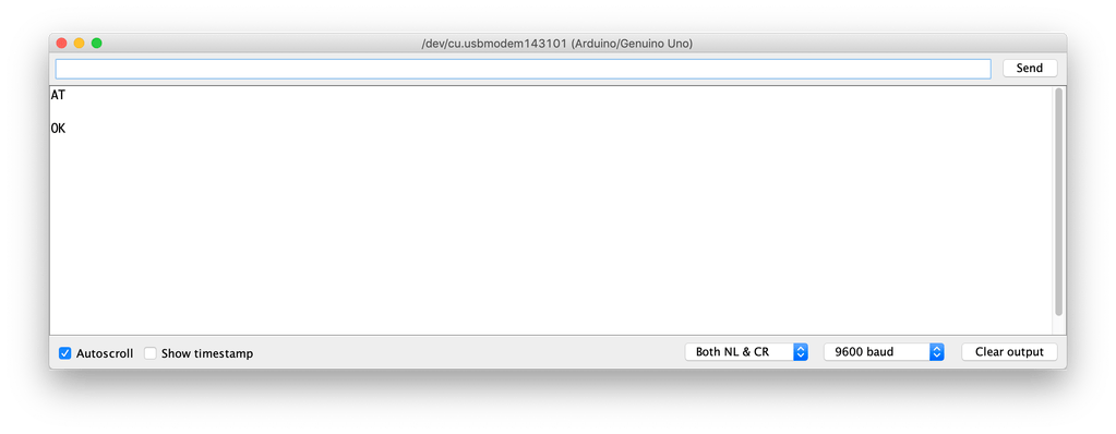
Langkah 3:Kirim “AT” dan tunggu tanggapan untuk memastikan modul ESP mendengarkan Anda.
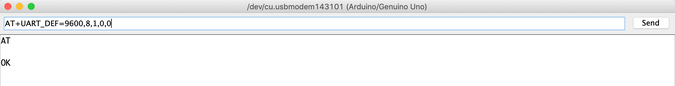
Langkah 4:Sekarang, ubah kecepatan komunikasi ESP8266-01
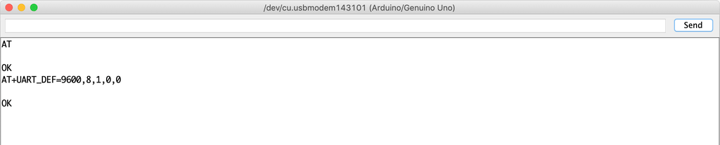
Firmware yang dimuat modul ESP8266-01 saya adalah 1.6. dan perintah ini AT+UART_DEF=,8,1,0,0 bekerja dengan baik untuk saya. Jika tidak berhasil dengan Anda, coba AT+CIOBAUD= ini . Jika merespons dengan “Oke” sekarang baud rate komunikasi modul ESP Anda berubah dari 115, 200 baud ke 9600 bau SELAMAT!
Mari kita ubah kecepatan komunikasi monitor Serial kembali ke 9600 dan kirim "AT" lagi untuk melihat apakah modul ESP dapat mendengar kita pada Kecepatan baru (9600) atau tidak.
LIHAT! bekerja. ESP8266-01 sekarang dapat berkomunikasi dengan papan Arduino pada 9600 baud rate, bukan 115,200 baud rate.
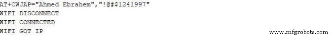
Sekarang, mari kita coba sambungkan dengan jaringan Wifi
Setelah Anda menekan enter, ESP8266-01 akan mencari jaringan ini dan menghubungkannya. Jika proses berhasil akan mengembalikan ini
WIFI TERHUBUNG
WIFI MENDAPAT IP
Pada titik ini, kami berhasil mengubah kecepatan komunikasi ESP8266-01 dari 115.200 baud menjadi 9600 baud. Sekarang, kita perlu membangun panel kontrol (Halaman Web) yang akan digunakan pengguna untuk mengontrol peralatan rumahnya. Jadi, mari kita bangun!
Apa itu Internet?
Sebenarnya, internet adalah kabel yang terkubur di bawah tanah, bisa berupa serat optik, tembaga, atau bahkan satelit, tetapi internet hanyalah sebuah kabel. Dua komputer yang terhubung ke kabel itu dapat berkomunikasi. Jika komputer terhubung langsung untuk kabel itu disebut server dan jika tidak terhubung langsung ke kabel itu disebut klien .
Server: adalah komputer khusus yang menjalankan sistem Operasi tertentu seperti Apache, komputer khusus ini menyimpan beberapa halaman web, file, database pada disk drive-nya. setiap server yang terhubung ke internet memiliki Alamat IP unik seperti 172.217.171.228 , alamat IP seperti nomor telepon membantu orang untuk menemukan satu sama lain dengan mudah. Karena itu Alamat IP tidak mudah diingat oleh manusia. Jadi, kami hanya memberinya nama google.com (Nama domain).
Klien: ini adalah komputer seperti yang Anda dan saya gunakan setiap hari, terhubung secara tidak langsung ke internet melalui penyedia layanan internet (ISP) dan juga memiliki alamat IP yang unik.
Skenario Kerja
Sederhananya, ini dimulai dengan permintaan yang dikirim dari browser web (Klien) seperti google chrome, firefox dan diakhiri dengan respons yang diterima dari server web.
Anda memasukkan URL situs web makesomestuff.org di browser dari komputer (klien), lalu browser ini mengirimkan permintaan ke server web yang menghosting situs web, server web kemudian mengembalikan respons berisi halaman HTML atau format dokumen lain apa pun ke browser untuk ditampilkan itu.
Tepat, itulah yang perlu kita lakukan hari ini dalam proyek kita. Kita perlu mengirim permintaan dari browser web (Klien) ke ESP8266-01 (Server Web) yang keduanya terhubung ke jaringan lokal yang sama. Permintaan ini berisi beberapa data yang memberi tahu Arduino apa yang harus dilakukan untuk menghidupkan atau mematikan bola lampu. Jadi, mari buat halaman web!
Membangun Halaman Web
Untuk membangun halaman web kita, kita harus berurusan dengan HTML, CSS, Javascript. jika Anda belum pernah mendengar tentang nama-nama ini sebelumnya, jangan khawatir saya mengerti.
HTML: Singkatan dari "HyperText markup language" kami menggunakannya untuk membangun struktur utama halaman web apa pun. Seperti menambahkan beberapa tombol, gambar, paragraf, header, tabel, dan masih banyak lagi elemen lainnya. itu terdiri dari serangkaian elemen yang memberi tahu browser cara menampilkan konten halaman web. elemen ini diwakili oleh sesuatu yang disebut tag.
CSS: Itu singkatan dari cascading style sheet. Setelah membangun struktur utama halaman web, Anda perlu membuat struktur ini terlihat bagus, inilah CSS untuk membuat beberapa gaya. itu adalah bahasa yang menggambarkan gaya elemen HTML. ini terdiri dari beberapa selektor dan blok deselerasi.
Javascript: itu adalah bahasa pemrograman yang akan kita gunakan untuk membuat halaman web lebih interaktif seperti menambahkan beberapa animasi, peta dan memungkinkan kita untuk membuat beberapa hal kompleks di halaman web. Terutama, kami akan menggunakannya hari ini untuk mengirim permintaan HTTP dari klien (browser web) ke server web (ESP8266-01) untuk mengambil beberapa tindakan seperti menyalakan atau mematikan bola lampu.
Bangun Struktur Halaman Web
Untuk dengan mudah memahami penjelasan yang akan datang, saya sarankan Membaca ini keren Pengantar HTML.
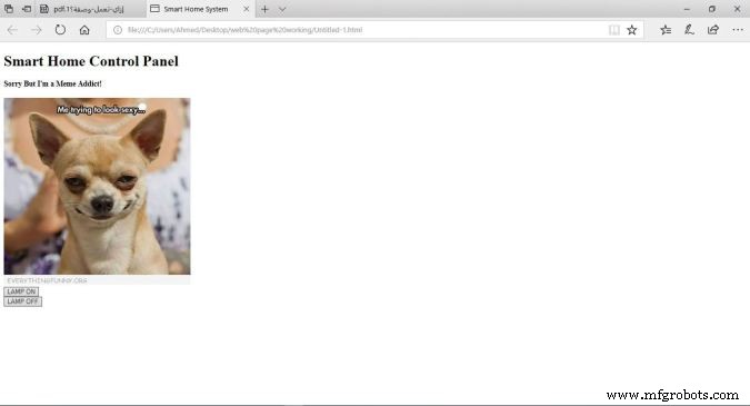
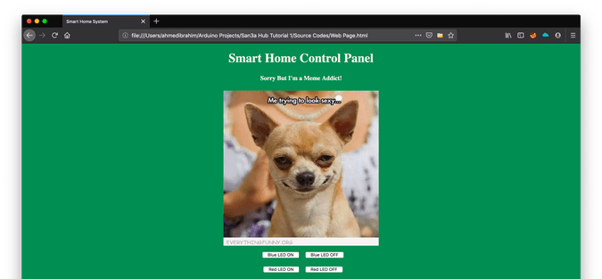
Seperti yang kita lihat, panel kontrol kita sangat sederhana, ini berisi dua header yang masing-masing memiliki ukuran berbeda, satu gambar, dan dua tombol satu untuk menyalakan LED dan yang kedua untuk mematikannya.
Kode
Sistem Rumah Pintar
Panel Kontrol Rumah Pintar
Maaf Tapi Saya Pecandu Meme!
Penjelasan Kode
: deklarasi mendefinisikan bahwa dokumen ini adalah dokumen HMTL5.
: elemen akar halaman HTML.
: elemen berisi informasi meta tentang halaman.
:</strong> elemen menentukan judul dokumen. judul ini muncul di tab browser halaman web.</li>
<li><strong><body>:</strong> elemen berisi konten halaman web yang terlihat.</li>
<li><strong><h1>:</strong> elemen mendefinisikan elemen besar.</li>
<li><strong><h4>:</strong> elemen mendefinisikan header yang lebih kecil. ketika nilai header berkurang, font berkurang.</li>
<li><strong><img>:</strong> elemen menambahkan gambar ke halaman web. gambar yang ingin Anda tampilkan harus berada di folder proyek yang sama.</li>
<li><strong><br>:</strong> memajukan kursor ke baris baru.</li>
<li><strong><button>:</strong> elemen menambahkan tombol ke konten halaman.</li>
</ul>
<p>
Setiap tombol adalah halaman web kami memiliki dua atribut yang sangat penting <code>id</code> , dan <code>kelas</code> atribut. kita akan berbicara tentang mengapa kita menetapkan dua nilai ini ke tombol dalam penjelasan kode Jquery.</P> <h3 id='toc-styling-the-web-page-12'> <p>
<p>
</P> </P> Menata Gaya Halaman Web</h3> <p>
<strong><em>Untuk dengan mudah memahami penjelasan yang akan datang, saya sarankan Membaca ini keren </em> </strong> <strong><em>Pengantar CSS</em> </strong> <strong><em>.</em> </strong> </P> <img loading='lazy' src="https://www.mfgrobots.com/article/uploadfiles/202112/2021122812180042.jpg?auto=compress%2Cformat&w=680&h=510&fit=max" /></figure> <p>
Sekarang, halaman web terlihat lebih bagus (TIDAK TERLALU BANYAK xD) kami memberikannya warna latar belakang hijau yang sejuk, kami membuat konten halaman rata di tengah, dan kami mengubah warna font header dan keluarga font yang membuat halaman web lebih hidup. Kami menggunakan CSS untuk melakukan semua hal penataan ini.</P> <p>
<strong>Kode</strong> </P> <pre><code><!DOCTYPE html> <html> <head> <title>Sistem Rumah Pintar
Panel Kontrol Rumah Pintar
Maaf Tapi Saya Pecandu Meme!
Penjelasan Kode
Kami menambahkan beberapa baris kode untuk membuat halaman web kami terlihat lebih bagus. Kami menambahkan style="background-color:seagreen; color:seashell; text-align:center;" di dalam tubuh tag untuk membuat semua konten halaman web di tengah halaman dan untuk mengatur warna latar belakang menjadi hijau laut juga untuk mengatur warna font menjadi kerang .
Kami juga menambahkan style="margin:10px;" di dalam dua tag tombol untuk menyetel margin 10 piksel di sekitar empat sisi setiap tombol.
Mengirim Permintaan Ke Server Web
Untuk dengan mudah memahami penjelasan yang akan datang, saya sarankan Membaca ini keren Pengantar Jquery.
Sekarang, setelah membangun struktur halaman web kita dan menatanya, kita perlu menambahkan beberapa fungsionalitas ke dua tombol yang kita tambahkan sebelumnya di halaman web. kita perlu ketika pengguna mengklik tombol "LAMP ON" browsernya mengirimkan permintaan berisi beberapa data unik ke server (ESP8266-01) data unik ini memberitahu Arduino untuk menyalakan lampu. Hal yang sama dengan tombol kedua “LAMP OFF” ketika pengguna mengkliknya, browser akan mengirimkan permintaan berisi beberapa data unik ke server (ESP8266-01) data unik ini memberitahu Arduino untuk mematikan lampu. Mari kita lihat kodenya.
Sistem Rumah Pintar
Panel Kontrol Rumah Pintar
Maaf Tapi Saya Pecandu Meme!
Penjelasan Kode
Hal Pertama Pertama, kita perlu mengimpor perpustakaan Jquery dalam kode kita. Jadi, kami menambahkan baris ini di tag kepala .
Semua keajaiban terjadi di bagian yang menarik ini.
$(".button").click(function() {
Saat pengguna mengeklik tombol apa pun yang terkait dengan kelas “tombol” , memicu fungsi berikut.
var p =$(this).attr('id');
Dapatkan nilai atribut tombol yang diklik “id” dan simpan di dalam “p” variabel.
pin:p
Masukkan nilai variabel “p” ke dalam kamus (nilai kunci) kuncinya adalah “pin” dan nilainya adalah nilai variabel “p”.
$.get("http://172.20.10.11:80/", { pin:p });});
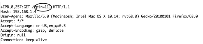
Kemudian, kirim permintaan GET ke server web yang alamat IP-nya adalah "172.20.10.11". DAPATKAN . ini request berisi nilai atribut id tombol yang ditekan.
Jika pengguna menekan tombol “LAMP ON” nilai id ini akan menjadi 111, sehingga header permintaan GET akan berisi beberapa data seperti ini pin=111 . lihat gambar selanjutnya!
Di sisi yang berlawanan, jika pengguna menekan tombol “LAMP OFF”, permintaan akan berisi data ini pin=110 .
Logika Kode
Saya tahu Anda bertanya sekarang mengapa dia memilih 111 dan 110 secara khusus? Ok, biar dijawab fam. Sebenarnya, angka 111 dan 110 membelah menjadi dua bagian.
Bagian satu: adalah dua angka pertama yang dalam kedua kasus akan menjadi “11”, ini mengacu pada nomor pin Arduino yang terhubung dengan beban yang perlu saya kendalikan.
Bagian dua: adalah angka ketiga yang berubah antara 1 dan 0 tergantung pada tombol yang diklik. Dan itu mengacu pada status pin (ON atau OFF).
Dalam kode Arduino, kita akan menerima data ini dan memisahkan kedua bagian ini satu sama lain dan menyimpan setiap bagian dalam variabel yang berbeda, bagian pertama dalam variabel pinNumber dan bagian kedua dalam variabel pinState , maka kita akan menulis baris kode sederhana ini untuk mengontrol beban yang terhubungdigitalWrite(pinNumber, pinState);
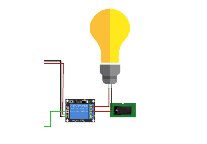
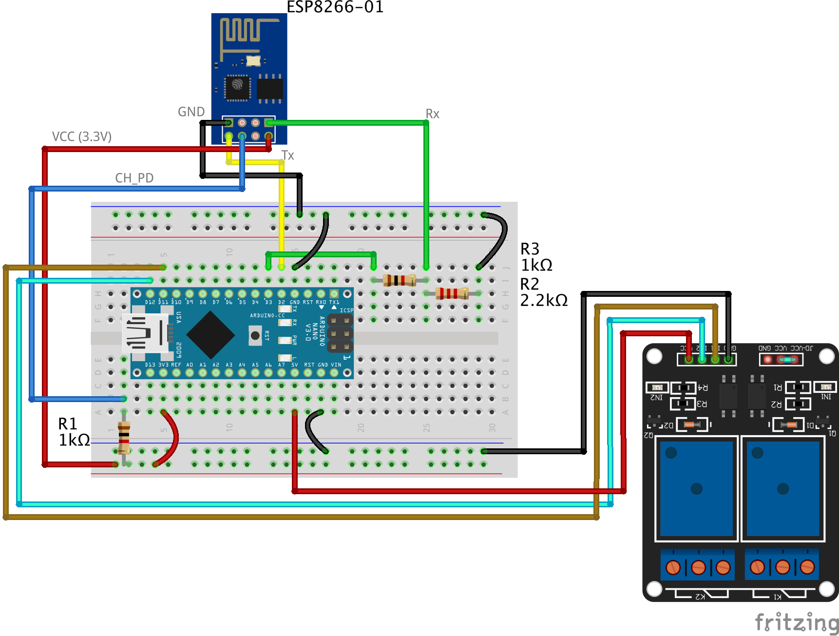
Menghubungkan Beban
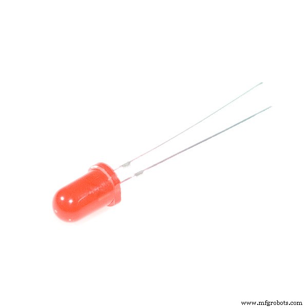
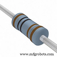
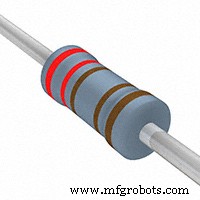
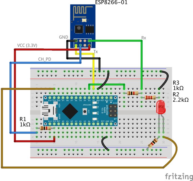
Sekarang, kita perlu menghubungkan beban dengan papan Arduino untuk mengontrolnya. Sebelum menghubungkan perangkat bertegangan tinggi seperti AC atau bahkan TV, kita perlu menguji sirkuit dan kode kita dengan beberapa benda bertegangan rendah seperti LED hanya untuk memastikan semuanya berfungsi dengan baik. Berikut diagram pengkabelan
Pengkabelannya cukup sederhana, kami menghubungkan kaki positif LED ke pin digital Arduino 11, dan kaki negatif ke GND melalui resistor 1k ohm.
Kode Arduino
#include //termasuk library SoftwareSerial akan memungkinkan Anda untuk menggunakan pin no. 2,3 sebagai Rx, Tx. SoftwareSerial esp8266(2,3); //set Rx ==> Pin 2; TX ==> Pin3. #define serialCommunicationSpeed 9600 // <==========tentukan konstanta bernama "serialCommunicationSpeed" dengan nilai 9600. Ini merujuk pada kecepatan komunikasi serial Perangkat Lunak dan perangkat keras (baud rate). #define DEBUG true //buat konstanta bernama "DEBUG" dan nilainya benar. kita akan menggunakannya nanti. int LED merah =12; // menetapkan variabel bernama "redLED" dengan nilai integer 12, ini mengacu pada pin yang terhubung dengan LED merah. int LED biru =11; //menetapkan variabel bernama "blueLED" dengan nilai integer 11, ini mengacu pada pin yang terhubung dengan LED biru. void setup() { pinMode(LED merah,OUTPUT); //set pin nomor 12 sebagai pin output. pinMode (LED biru, OUTPUT); //set pin nomor 11 sebagai pin output. digitalWrite(LED merah,RENDAH); //mematikan LED merah di awal program. digitalWrite (LED biru, TINGGI); //nyalakan LED biru di awal program. Serial.begin(serialCommunicationSpeed); //memulai komunikasi serial Perangkat Keras (0, 1) pada kecepatan 9600. esp8266.begin(serialCommunicationSpeed); //mulai komunikasi serial perangkat lunak (2, 3) dengan kecepatan 9600. InitWifiModule(); //panggil fungsi yang ditentukan pengguna ini "InitWifiModule()" untuk menginisialisasi komunikasi antara ESP8266 dan titik akses Anda (Router Rumah atau bahkan hotspot seluler Anda). digitalWrite(LED biru,RENDAH); //setelah berhasil melakukan inisialisasi, matikan LED biru (hanya sebagai indikator). } void loop() //our main program, some fun are about to start) { if(esp8266.available()) //if there's any data received and stored in the serial receive buffer, go and excute the if-condition body. If not, dont excute the if-condition body at all. { if(esp8266.find("+IPD,")) //search for the "+IPD," string in the incoming data. if it exists the ".find()" returns true and if not it returns false. { delay(1000); //wait 1 second to fill up the buffer with the data. int connectionId =esp8266.read()-48; //Subtract 48 because the read() function returns the ASCII decimal value. And 0 (the first decimal number) starts at 48. We use it to convert from ASCI decimal value to a character value. esp8266.find("pin="); //Advance the cursor to the "pin=" part in the request header to read the incoming bytes after the "pin=" part which is the pinNumer and it's state. int pinNumber =(esp8266.read()-48)*10; //read the first Byte from the Arduino input buffer(i.e. if the pin 12 then the 1st number is 1) then multiply this number by 10. So, the final value of the "pinNumber" variable will be 10. pinNumber =pinNumber + (esp8266.read()-48); //read the second Byte from the Arduino input buffer(i.e. if the pin number is 12 then the 2nd number is 2) then add this number to the first number. So, the final value of the "pinNumber" variable will be 12. int statusLed =(esp8266.read()-48); //read the third byte from the Arduino input buffer. then save it inside the "statusLed" variable. At any case, it will be 1 or 0. digitalWrite(pinNumber, statusLed); //then turn the LED at "pinNumber" on or off depending on the "statusLed" variable value. Serial.println(connectionId); //print the "connectionId" value on the serial monitor for debugging purposes. Serial.print(pinNumber); //print the "pinNumber" value on the serial monitor for debugging purposes. Serial.print(""); //print some spaces on the serial monitor to make it more readable. Serial.println(statusLed); //print the "statusLed" value on the serial monitor for debugging purposes. String closeCommand ="AT+CIPCLOSE="; //close the TCP/IP connection. closeCommand+=connectionId; //append the "connectionId" value to the string. closeCommand+="\r\n"; //append the "\r\n" to the string. it simulates the keyboard enter press. sendData(closeCommand,1000,DEBUG); //then send this command to the ESP8266 module to excute it. } } } /****************************************************************************************************************************************************************************************** * Name:sendData * Description:this Function regulates how the AT Commands will ge sent to the ESP8266. * * Params:command - the AT Command to send * - timeout - the time to wait for a response * - debug - print to Serial window?(true =yes, false =no) * * Returns:The response from the esp8266 (if there is a reponse) */ String sendData(String command, const int timeout, boolean debug) { String response =""; //initialize a String variable named "response". we will use it later. esp8266.print(command); //send the AT command to the esp8266 (from ARDUINO to ESP8266). waktu int panjang =milis(); //get the operating time at this specific moment and save it inside the "time" variable. while( (time+timeout)> millis()) //excute only whitin 1 second. { while(esp8266.available()) //is there any response came from the ESP8266 and saved in the Arduino input buffer? { char c =esp8266.read(); //if yes, read the next character from the input buffer and save it in the "response" String variable. response+=c; //append the next character to the response variabl. at the end we will get a string(array of characters) contains the response. } } if(debug) //if the "debug" variable value is TRUE, print the response on the Serial monitor. { Serial.print(response); } return response; //return the String response. } /****************************************************************************************************************************************************************************************** * Name:InitWifiModule * Description:this Function gives the commands that we need to send to the sendData() function to send it. * * Params:Nothing. * * Returns:Nothing (void). */ void InitWifiModule() { sendData("AT+RST\r\n", 2000, DEBUG); //reset the ESP8266 module. //tunda(1000); sendData("AT+CWJAP=\"PUT YOUR SSID\",\"PUT YOUR PASSWORD\"\r\n", 2000, DEBUG); //connect to the WiFi network. delay (3000); sendData("AT+CWMODE=1\r\n", 1500, DEBUG); //set the ESP8266 WiFi mode to station mode. penundaan (1000); sendData("AT+CIFSR\r\n", 1500, DEBUG); //Show IP Address, and the MAC Address. penundaan (1000); sendData("AT+CIPMUX=1\r\n", 1500, DEBUG); //Multiple conections. penundaan (1000); sendData("AT+CIPSERVER=1,80\r\n", 1500, DEBUG); //start the communication at port 80, port 80 used to communicate with the web servers through the http requests. }
code explanation
the code is pretty straightforward, we implemented two different functions InitWifiModule() and sendData()
The sendData() function job is regulating how the AT commands will get sent to the ESP8266-01 module.
the InitWifiModule() function job is to provide the sendData() function the AT commands that we need to send to the ESP8266-01.
in the loop() function we read the income HTTP request header and search for the “+IPD, ” which means that the request has successfully arrived, then we read the pin value which it will be “111” if the user clicked the “LAMP ON” button and “110” if the user clicked “LAMP OFF” button.
Don’t forget to put your wifi SSID and Password in the Arduino code line no. 103sendData("AT+CWJAP=\"PUT YOUR SSID\",\"PUT YOUR PASSWORD\"\r\n", 2000, DEBUG);
For more code explanation please read the comments in the code, it’s well documented
Cara Kerjanya
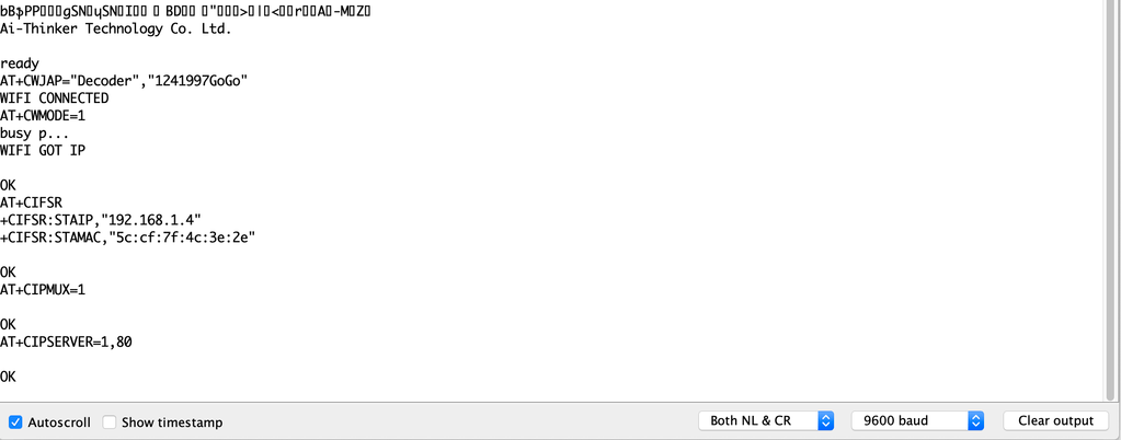
After uploading the code to the Arduino board, open the Serial monitor and read the responses that the ESP module is sending.
at the beginning of the program, if you see something like the previous figure with “OK” at the end of the page, it means that the ESP8266-01 module is successfully connected to your wifi (Access point) and got an IP and MAC address. Now, you can open your fancy web page and try to control some stuff 😉
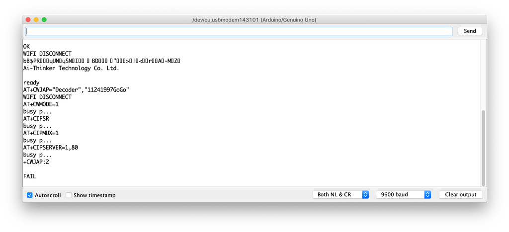
But, if you see something like the previous figure with a “FAIL” or “ERROR” at the end of the page, it means that your ESP module cant connect to your wifi (Access point) for some reasons, try to check if entered the right SSID and password for your network.
Adding a High Voltage Load
After we tested our code and got sure that everything is working like a charm, we need to replace this boring LED with a High voltage load like an air conditioner, TV or a light bulb. But to control all of these high voltage appliances we have to deal with relays .
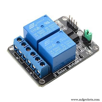
What’s and why relays? Ok, the relay is a mechanical switch, which is toggled on or off by energizing a coil. it’s mainly used to control a high powered circuit using a low power signal (5V or 0V). So we can control a high powered device like an air conditioner or an AC lamp turning it on or off only by a 5V or 0V signal. Which is amazing!
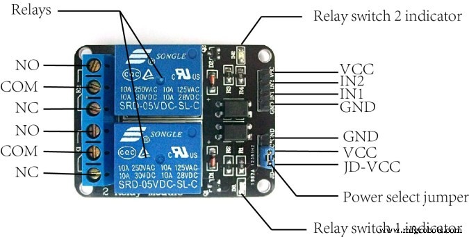
The Two-channel relay module has two control pins(IN1, IN2) these pins should get connected to two Arduino digital pins to control the state of the two coils, closes or opens the load circuit.
At the opposite side of the relay module, the COM(common) should get connected to one end of the load. the other end of the load is either connected to the NC(Normally Close) or NO(Normally open) , if connected to the NO the load remains Disconnected before trigger and vice versa.
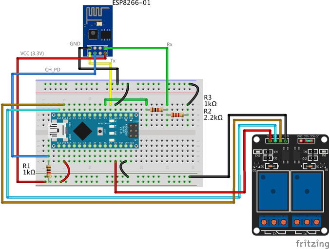
Wiring Diagram
As you see, we are using a two-channel relay module that gives us the ability to control two different AC loads. We are connecting the first relay at digital output pin11(Arduino) and the second relay to digital output pin 12(Arduino)
We will make a small modification to our web page, we will add another two buttons(ON and OFF) to control the second connected load.
Smart Home System
Smart Home Control Panel
Sorry But I'm a Meme Addict!
How It Works
Just like the last trial, You upload the Arduino code to the board (if not uploaded yet) and open the serial monitor and make sure that your ESP module is connected successfully to your access point and got an IP and MAC address.
Then open your fancy web page and start controlling your stuff 😉
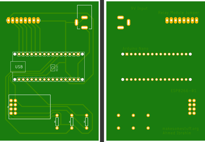
Make it more professional!
What about transferring our breadboard circuit to a professional printed circuit board (PCB) to make our project more rigid and solid, I designed the project circuit using Autodesk Eagle software. all the PCB files are open-source you can access it from this link:https://www.pcbway.com/project/shareproject/IoT_Using_Arduino_and_ESP8266_01.html
Because we love open source 😉
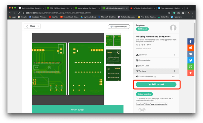
You can order your own PCB From PCBWay company these guys have a very good reputation in this field and they ship to more than 170 countries around the world with reasonable prices. all you have to do is to open the project PCB files link and press “Add to cart”. That’s it!
Troubleshooting
if your ESP Module is successfully connected to your access point but there is no action happens when you click the web page buttons
make sure that you are sending the request from your web browser from port 80(HTTP). example:
$.get("http://192.168.1.4:80/"
make sure that your PC or Laptop and the ESP module is connected to the same Access point.
In Jquery code, make sure that you wrote the right ESP module IP address.
Make sure that you are connecting the load at Arduino digital pins 11 and 12.
Don’t forget to save the Web page code file after any change or modification, and reload the web page in the web browser after any code modification to take effect.
Final
We are done! in today’s tutorial, we learned how to build a simple web page using HTML, CSS, and jquery. Also, we learned how to control an AC load wirelessly from a web-based control panel, and how to use the awesome ESP8266-01 Wifi module with the Arduino board.
you wanna see more Tutorials and open source projects you can also visit my blog www.makesomestuff.org
Lastly, if you have any questions drop it in the comments section below, I will be more than happy to hear from you 😉
Kode
Web Page
Final Arduino Code
Web PageHTML
Smart Home System
Smart Home Control Panel
Sorry But I'm a Meme Addict!
Final Arduino CodeArduino
#include //including the SoftwareSerial library will allow you to use the pin no. 2,3 as Rx, Tx.SoftwareSerial esp8266(2,3); //set the Rx ==> Pin 2; TX ==> Pin3.#define serialCommunicationSpeed 9600 // <=========define a constant named "serialCommunicationSpeed" with a value 9600. it referes to the Software and hardware serial communication speed(baud rate).#define DEBUG true //make a constant named "DEBUG" and it's value true. we will use it later.int redLED =12; //assign a variable named "redLED" with an integer value 12, it refers to the pin which the red LED is connected on.int blueLED =11; //assign a variable named "blueLED" with an integer value 11, it refers to the pin which the blue LED is connected on.void setup(){ pinMode(redLED,OUTPUT); //set the pin number 12 as an output pin. pinMode (LED biru, OUTPUT); //set the pin number 11 as an output pin. digitalWrite(redLED,LOW); //turn the red LED off at the beginning of the program. digitalWrite (LED biru, TINGGI); //turn the blue LED on at the beginning of the program. Serial.begin(serialCommunicationSpeed); //begin the Hardware serial communication (0, 1) at speed 9600. esp8266.begin(serialCommunicationSpeed); //begin the software serial communication (2, 3) at speed 9600. InitWifiModule(); //call this user-defined function "InitWifiModule()" to initialize a communication between the ESP8266 and your access point (Home Router or even your mobile hotspot). digitalWrite(LED biru,RENDAH); //after finishing the initialization successfully, turn off the blue LED (just an indicator).}void loop() //our main program, some fun are about to start){ if(esp8266.available()) //if there's any data received and stored in the serial receive buffer, go and excute the if-condition body. If not, dont excute the if-condition body at all. { if(esp8266.find("+IPD,")) //search for the "+IPD," string in the incoming data. if it exists the ".find()" returns true and if not it returns false. { delay(1000); //wait 1 second to fill up the buffer with the data. int connectionId =esp8266.read()-48; //Subtract 48 because the read() function returns the ASCII decimal value. And 0 (the first decimal number) starts at 48. We use it to convert from ASCI decimal value to a character value. esp8266.find("pin="); //Advance the cursor to the "pin=" part in the request header to read the incoming bytes after the "pin=" part which is the pinNumer and it's state. int pinNumber =(esp8266.read()-48)*10; //read the first Byte from the Arduino input buffer(i.e. if the pin 12 then the 1st number is 1) then multiply this number by 10. So, the final value of the "pinNumber" variable will be 10. pinNumber =pinNumber + (esp8266.read()-48); //read the second Byte from the Arduino input buffer(i.e. if the pin number is 12 then the 2nd number is 2) then add this number to the first number. So, the final value of the "pinNumber" variable will be 12. int statusLed =(esp8266.read()-48); //read the third byte from the Arduino input buffer. then save it inside the "statusLed" variable. At any case, it will be 1 or 0. digitalWrite(pinNumber, statusLed); //then turn the LED at "pinNumber" on or off depending on the "statusLed" variable value. Serial.println(connectionId); //print the "connectionId" value on the serial monitor for debugging purposes. Serial.print(pinNumber); //print the "pinNumber" value on the serial monitor for debugging purposes. Serial.print(""); //print some spaces on the serial monitor to make it more readable. Serial.println(statusLed); //print the "statusLed" value on the serial monitor for debugging purposes. String closeCommand ="AT+CIPCLOSE="; //close the TCP/IP connection. closeCommand+=connectionId; //append the "connectionId" value to the string. closeCommand+="\r\n"; //append the "\r\n" to the string. it simulates the keyboard enter press. sendData(closeCommand,1000,DEBUG); //then send this command to the ESP8266 module to excute it. } }}/******************************************************************************************************************************************************************************************* Name:sendData* Description:this Function regulates how the AT Commands will ge sent to the ESP8266.* * Params:command - the AT Command to send * - timeout - the time to wait for a response * - debug - print to Serial window?(true =yes, false =no)* * Returns:The response from the esp8266 (if there is a reponse)*/String sendData(String command, const int timeout, boolean debug){ String response =""; //initialize a String variable named "response". we will use it later. esp8266.print(command); //send the AT command to the esp8266 (from ARDUINO to ESP8266). waktu int panjang =milis(); //get the operating time at this specific moment and save it inside the "time" variable. while( (time+timeout)> millis()) //excute only whitin 1 second. { while(esp8266.available()) //is there any response came from the ESP8266 and saved in the Arduino input buffer? { char c =esp8266.read(); //if yes, read the next character from the input buffer and save it in the "response" String variable. response+=c; //append the next character to the response variabl. at the end we will get a string(array of characters) contains the response. } } if(debug) //if the "debug" variable value is TRUE, print the response on the Serial monitor. { Serial.print(response); } return response; //return the String response.}/******************************************************************************************************************************************************************************************* Name:InitWifiModule* Description:this Function gives the commands that we need to send to the sendData() function to send it.* * Params:Nothing.* * Returns:Nothing (void).*/void InitWifiModule(){ sendData("AT+RST\r\n", 2000, DEBUG); //reset the ESP8266 module. //tunda(1000); sendData("AT+CWJAP=\"Decoder\",\"1241997GoGo\"\r\n", 2000, DEBUG); //connect to the WiFi network. delay (3000); sendData("AT+CWMODE=1\r\n", 1500, DEBUG); //set the ESP8266 WiFi mode to station mode. delay (1500); sendData("AT+CIFSR\r\n", 1500, DEBUG); //Show IP Address, and the MAC Address. delay (1500); sendData("AT+CIPMUX=1\r\n", 1500, DEBUG); //Multiple conections. delay (1500); sendData("AT+CIPSERVER=1,80\r\n", 1500, DEBUG); //start the communication at port 80, port 80 used to communicate with the web servers through the http requests.}