motor NEMA. Masalah yang paling sering terjadi
Salah satu komponen dasar dalam printer 3D FFF adalah motor. Mereka bertanggung jawab untuk melakukan gerakan yang diperlukan untuk memposisikan kepala cetak, serta menarik filamen ke dalam ekstruder.
Motor yang digunakan adalah motor stepper, jenis yang paling umum adalah NEMA 17 dan NEMA 23.
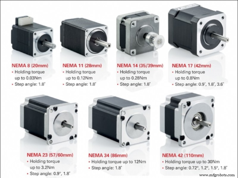
Gambar 1:Jenis motor NEMA. Sumber:motioncontrolproducts.com
Motor stepper berkualitas baik memiliki keandalan yang sangat tinggi, sehingga penyebab utama kegagalan motor biasanya bersifat eksternal, biasanya terkait dengan driver daya atau sambungan.
Motor stepper
Motor stepper adalah jenis motor yang berputar terus menerus. Rotasi terjadi dalam lompatan diskrit dari sudut tertentu. Ini adalah motor setengah jalan antara motor DC standar dan motor servo. Seperti motor DC, motor ini memungkinkan beberapa putaran 360 °, sekaligus memungkinkan pemosisian sudut yang presisi, seperti motor servo.
Yang paling umum digunakan dalam printer 3D adalah motor stepper hibrida bipolar, biasanya dalam format NEMA17 atau NEMA23. Motor hybrid menggabungkan kemampuan stepper kecil motor VR dengan kemampuan inersia tinggi motor magnet permanen. Di sisi lain, motor bipolar memberikan torsi dan jangkar yang lebih tinggi daripada motor unipolar sementara bobotnya lebih ringan dan ukurannya lebih kecil, namun memerlukan pengontrol daya khusus.
Saat memilih motor stepper, kita harus mengetahui karakteristik utamanya:
- Langkah: Ini adalah sudut minimum motor dapat berputar secara langsung (tanpa menggunakan pengontrol microstep). Kita biasanya dapat menemukan motor dengan langkah 1,8º atau 0,9º. Secara umum, langkah yang lebih kecil menyiratkan presisi yang lebih tinggi, tetapi juga kecepatan rotasi maksimum yang lebih rendah.
- Saat ini berfungsi: Ini adalah nilai arus maksimum di mana kita harus memberi makan motor agar berfungsi dengan baik. Semakin banyak arus yang kita berikan ke motor, semakin banyak torsi yang akan kita capai dan oleh karena itu akan mampu menahan inersia yang lebih besar tanpa kehilangan langkah, namun pemanasan dan keausan juga akan lebih besar. Menggunakan arus yang lebih tinggi dari yang ditentukan oleh pabrikan akan menyebabkan kerusakan dan kegagalan motor.
- Tegangan per fase: Ini adalah voltase yang dibutuhkan oleh masing-masing kumparan untuk beroperasi dengan benar.
- Resistensi fase: Ini adalah hambatan listrik yang disediakan oleh masing-masing kumparan.
- Induktansi fase: Nilai induktansi maksimum yang dihasilkan oleh masing-masing kumparan saat diaktifkan.
- Akurasi pemosisian: Penyimpangan maksimum yang dapat terjadi selama gerakan rotasi. Secara umum, nilai yang lebih rendah menunjukkan akurasi yang lebih tinggi.
- Suhu pengoperasian maksimum: Ini adalah suhu operasi maksimum yang dapat ditahan motor. Melebihi suhu ini untuk waktu yang lama akan menyebabkan kegagalan motor.
- Inersia rotor: Ini adalah inersia yang diberikan oleh rotor saat kosong karena beratnya sendiri. Kelembaman yang didukung oleh motor akan menjadi jumlah dari ini ditambah elemen yang digabungkan ke motor.
- Torsi atau menahan torsi: Ini adalah torsi maksimum yang dapat ditahan motor saat fase tidak aktif (tidak ada arus), tanpa menyebabkan poros berputar.
- Torsi jangkar: Ini adalah torsi maksimum yang dapat ditahan motor saat berhenti dan fase aktif (hidup), tanpa menyebabkan poros berputar. Nilai dipertimbangkan untuk motor yang disuplai dengan arus maksimum.
- Torsi awal: Ini adalah torsi yang diperlukan untuk mengatasi inersia rotor sehingga mulai berputar.
- Torsi putar: Ini adalah torsi maksimum yang dapat ditahan motor saat berputar tanpa menyebabkan kehilangan langkah. Nilai dipertimbangkan untuk motor yang disuplai dengan arus maksimum.
Jika kita mencari motor yang memungkinkan kita menggunakan kecepatan tinggi dan menahan inersia tinggi selama pergerakan, misalnya dalam kasus sumbu XY, kita harus memilih motor dengan langkah 1,8º dan torsi tinggi.
Motor sumbu Z tidak akan membutuhkan kecepatan kerja yang tinggi, sehingga motor 0,9º akan memberikan gerakan yang lebih halus. Dalam hal ini, motor dengan torsi penahan dan penahan maksimum harus dipilih untuk menopang bobot platform atau gantry (bergantung pada desain printer).
Sambungan motor stepper bipolar
Saat menyambungkan motor stepper dengan benar, sebaiknya sediakan lembar spesifikasi pabrikan, karena posisi kabel bervariasi dari satu model ke model lainnya.
Biasanya, motor stepper bipolar akan memiliki 4 koneksi yang terdiri dari dua rangkaian catu daya independen. Setiap sirkuit terdiri dari kutub positif dan negatif yang memasok daya ke masing-masing kumparan motor.
Hal pertama yang perlu diketahui adalah posisi keempat sambungan ini pada papan kontrol printer kita. Kami dapat menemukan dua jenis nomenklatur di papan kontrol. Yang pertama adalah 1A 1B 2A 2B, di mana setiap angka mewakili sirkuit dan huruf A dan B mewakili kutub. Yang kedua adalah A A
-
B B
-
di mana setiap huruf mewakili sirkuit dan aksen mewakili kutub negatif.
Setelah koneksi di papan ditentukan, hal yang sama harus dilakukan untuk motor.
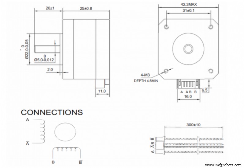
Gambar 2. Contoh sambungan pada lembar spesifikasi motor NEMA17. Sumber:Bondtech
Jika lembar spesifikasi tersedia, urutan kabel di konektor harus dikonsultasikan. Dalam hal ini, nomenklatur A A
-
B B
-
adalah yang paling umum.
Jika papan dan motor menggunakan nomenklatur yang sama, koneksinya sesederhana memasangkan setiap terminal. Jika mereka menggunakan nomenklatur yang berbeda, mereka harus dipasangkan sebagai berikut:
- 1A - A
- 1B - A
-
- 2A - B
- 2B - B
-
Jika lembar data motor tidak tersedia, pasangan sambungan dari setiap spul harus ditentukan. Ini dilakukan dengan mengukur resistansi pada semua kemungkinan kombinasi pasangan pin konektor. Ketika resistensi tidak terbatas, pasangan pertama telah ditemukan. Kombinasi yang paling umum digunakan oleh pabrikan motor adalah 1-3 4-6 atau 1-4 3-6, jadi mulailah dengan menguji kedua kombinasi ini.
Setelah ditemukan, setiap fase terhubung ke masing-masing gulungan. Penting agar kedua fase dihubungkan ke kumparan dalam polaritas yang sama, jadi jika kita menempatkannya dalam fase terbalik, saat mengirimkan arus ke motor tidak akan bergerak dan akan mengeluarkan suara. Dalam hal ini polaritas salah satu kumparan harus dibalik.
Sangat penting untuk memisahkan kedua fase, sehingga kondisi konektor harus sering diperiksa. Kontak yang buruk atau jembatan antar fase akan menyebabkan motor berhenti bekerja.
Mengatur arus motor
Motor stepper ditenagai melalui pengontrol atau driver khusus. Ada banyak model berbeda di pasaran. Kualitas yang lebih tinggi umumnya akan memberikan daya tahan lebih lama dan pengoperasian yang lebih tenang.
Dalam model yang tersedia, ada dua metode untuk menyesuaikan arus yang dikirim ke motor:
- Melalui sekrup penyetel. In general, lower quality or cheaper drivers allow the output current to be adjusted by means of a potentiometer in the form of a screw. In this case it is necessary to use a multimeter and a precision ceramic screwdriver to make the adjustment.
In this case the adjustment can be made in two ways:
- By Current:With the printer switched on and the motors connected, the current in one of the phases will be measured and adjusted to the appropriate value. This method is not recommended, especially the first time a new driver is connected, as the motors are initially powered without knowing if the output current is higher than the current admitted by the motor.
- By reference voltage:This is a slightly more complex method, but more recommendable. First we must determine the required reference voltage using the formula:
max · 8 · Rs
Where Imax is the maximum current at which the motor will be powered (usually at most 90 % of the maximum specified by the manufacturer) and Rs is the detection resistance of the driver.
To adjust it on the driver, simply power up the driver, measure the voltage between the Vref pin (usually the potentiometer itself) and a ground pin (usually the power supply pin) and set the appropriate value using the potentiometer.
- By firmware: Many current drivers do not have an adjustment potentiometer and allow the output current to be set directly by firmware. To do this, simply set the appropriate current value in the motor section of the firmware.
When selecting the output current of the drivers, it is not advisable to use the maximum value determined by the manufacturer. In order to prolong the service life of the motors, do not exceed 90 % of the manufacturer's maximum value, the optimum being the minimum current required to generate sufficient torque to withstand the inertias.
Higher current, in addition to higher torque, also means higher heating, higher motor noise and higher wear.
Maximum speed of a stepper motor
Stepper motors advance by pulses, so the maximum speed of the motor will depend on the maximum signal frequency that the control board is able to send. In addition, it must be taken into account that usually several motors are working simultaneously, so the frequency for each one will decrease.
For example, if the control board works at 100000 Hz and 4 motors (X,Y,Z and extruder) are working simultaneously, each motor will be controlled at 25000 Hz, or 25000 pulses per second. This means that a 1.9 ° motor without microstepping can rotate at a maximum of 125 rps. In a GT2 8-tooth belt drive system (the most common) this translates into a theoretical maximum linear speed of 3600 mm/s.
In the case of microstepping, the maximum speed would be reduced proportionally, so that if 16 microsteps are used, the maximum speed would be 225 mm/s, but if 256 microsteps are used, it would be reduced to only 14 mm/s.
It is very important to know the operating frequency of the control board, as the combination of a low output frequency with a high microstep setting can cause the maximum allowable speed to be lower than the printing speed, resulting in a significant loss of steps.
Appropriate setting of the steps per mm
When the motion signal is transmitted to the motor, it is sent as a rotation, however the movements included in the print files are linear. This is why the printer must be able to translate the angular movement into a linear one.
The movement is generally transmitted by means of toothed pulleys and belts, so that the step/mm conversion depends on the diameter of the pulleys.
To calculate this, the following formula is simply applied:
steps/mm = (360/P) · MS
2 · π · Rpulley
Where P is the motor pitch, MS the configured microsteps (1 in case of not using microstepping) and Rpulley the radius of the pulley used.
In the case of screw-transmitted movements, it is the pitch of the screw that defines the feed rate. For this purpose, the following formula is simply applied:
steps/mm = (360/P) · MS
A
Where P is the motor pitch, MS the configured microsteps (1 in case of not using microstepping) and A the pitch of the screw thread.
There are also many calculators that make it easier to obtain these values, such as the one offered by Prusa Printers.
Once these values have been obtained, and although in theory they are correct, it is advisable to carry out a precise calibration to compensate for possible manufacturing or assembly defects.
For this purpose, a cube of known dimensions (e.g. 50 x 50 x 50 mm) shall be printed out and the actual dimensions measured. Once this is done, the following formula shall be applied:
steps/mm = Dtheorical · Pactual
Dreal
where Dtheorical is the theoretical size that the part should have, Pactual is the current P/mm setting and Dreal is the measurement value obtained from the printed part.
By introducing the new P/mm value, you should obtain parts with appropriate dimensions.
Considerations to take into account
- Step loss: A step loss is usually caused by excessive torque in the engine. Large accelerations or high direction change speeds will cause inertias that the motor torque cannot compensate for, resulting in a step loss. Similarly, the combination of low signal frequencies and high microstep settings will drastically reduce the maximum motor speed. If the print speed exceeds this, a step loss will also occur. In any case, step loss in an open-loop printer will result in loss of position.
- Temperature: A high current setting will cause the motor to heat up. If the motor is inside a closed or heated structure that does not allow the heat to dissipate correctly, the working temperature may be exceeded, causing the demagnetisation of the magnets and a malfunction or breakdown of the motor. In closed printers, it is advisable to place the motors outside the chamber or, if this is not possible, to reduce the current to the minimum necessary.
- Hysteresis: This is a phenomenon intrinsic to motors. It can cause a small position error at the end of a movement. Using quality motors will reduce this error.
- Resonance: All motors have a natural frequency. If the pulse frequency sent to the motor is similar to the natural frequency, a resonance effect will occur. This will cause increased vibration, noise and wear.
- Step settings: Improper step/mm settings will result in positioning error, which will be reflected in dimensional errors in the parts.
- Connection: Mixing or bridging phases will cause the motor to not turn or to turn erratically. Placing one phase with the polarity reversed with respect to the other will cause the motor not to turn. Reversing the polarity of both phases, when connected correctly, will cause the motor to rotate in the opposite direction.
This guide discusses concepts in a general way and does not focus on a particular make or model, although they may be mentioned at some point. There may be important differences in calibration or adjustment procedures between different makes and models, so it is recommended that the manufacturer's manual be consulted before reading this guide.


