Pengontrol Pemoleng DIY untuk 862D+—Presisi & Keandalan
Komponen dan Perlengkapan
Arduino Nano R3 – 1 unit
Dioda Flyback Biasa – 1 unit
MOSFET irf540n n-channel – 1 unit
Regulator linier 5v – 1 unit
Resistor 330 ohm – 1 unit
Pin headers (jantan) – 2 unit
Oled .96 inci – 1 unit
Alat dan Mesin yang Diperlukan
Pemoleng (umum)
Bor 8mm /w bor
Tentang Proyek
Update (10/21/2019): Pembaruan besar pada kode. Juga baca di bawah ini. Sebagian diubah.
Pemoleng 862D+ saya rusak, jadi daripada membeli yang baru saya mengambil pemoleng kedua dan memperbaikinya. Bagian ter sulit adalah tidak ada solusi di mana pun online. PCB rusak karena setelah mengganti pemoleng masih menunjukkan S-E atau kesalahan sensor.
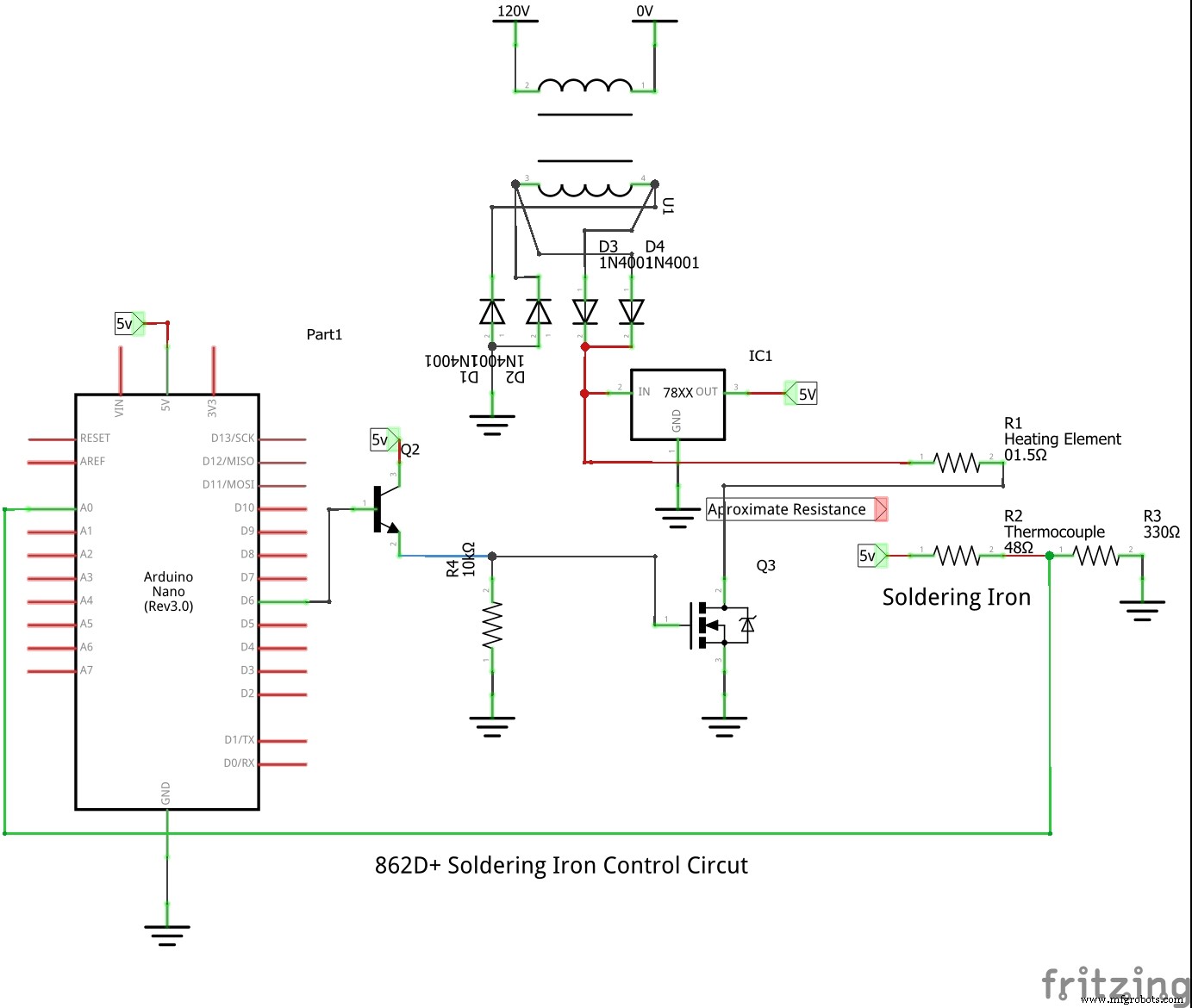
Jadi saya memutuskan untuk membuat rangkaian kontrol sendiri dan memasukkannya di dalam. Ini memerlukan transformator kedua tetapi karena murah, ada banyak ruang di dalam.
Mungkin tidak terlihat bagus, tetapi bekerja dengan baik. Sebagai bonus, saya menghilangkan tombol daya pemoleng, dan menambahkannya antara 5v dan arduino.
Berikut adalah tips pembuatan:
Semua bagian dapat dibeli sekarang. LCSC adalah situs elektronik grosir. Pengiriman mahal ke Amerika, tetapi komponen sangat murah.
MOSFET di Amazon $6 tetapi MOSFET di LCSC 32 sen. Namun barang seperti resistor harus dibeli dalam jumlah besar. Tetapi, 50 resistor secara harfiah 0,84 sen.
PASTIKAN MELINDUNGI KABEL DATA PANJANG dengan foil aluminium yang di-ground atau sesuatu lainnya. Kabel layar 12c misalnya.
Dalam kode:
1023 paling dingin 0 lava. Ubah settemp sesuai keinginan Anda. Beberapa di sekitar 600 biasanya.
Pengontrol pemoleng dapat mendeteksi apakah pemoleng Anda terhubung atau rusak. Jika pemoleng terputus, arduino akan nolkan input analog. Jika pemoleng biasa memanaskan dengan baik, tetapi tidak sekarang: putuskan pemoleng, tunggu sampai katanya colokkan pemoleng, lalu Anda siap. (Ini telah menjadi masalah bagi saya)
Sekarang Anda tahu dasar-dasar pemoleng Anda. Ini bisa menjadi alternatif murah untuk membeli pemoleng berkualitas. Meskipun ada pemoleng berkualitas lebih tinggi, ini sangat murah dan DIY.
Kode
Control Code
The Code
Code Updated 10/21/2019
Control CodeC/C++
Paste this into the arduino and upload. This only works with the circuit provided
int output = 0; int temp = 0; int settemp = 630; String inputString = ""; // a string to hold incoming data boolean rap = false; boolean stringComplete = false; // whether the string is complete int t = 0; void setup() { Serial.begin(9600); inputString.reserve(200); pinMode(6, OUTPUT); digitalWrite(6, LOW); } void loop() { serialEvent(); if (stringComplete) { Serial.println(inputString); t = inputString.toInt(); //settemp = t //sets the set temp to the serial input inputString = ""; stringComplete = false; } rapid(); pid(); } void rapid() { //Controls the soldering iron by rapidly heating it up in the beginning. if (rap == false) { digitalWrite(6, HIGH); do { temp = analogRead(0); Serial.print("rapid"); Serial.println(temp); } while (temp - settemp > 10); digitalWrite(6, LOW); rap = true; } } void pid() { //Controls the soldering with slow active power heating. temp = analogRead(0); output = temp - settemp; if (output < 0) { output = 0; } if (output > 255) { output = 255; } Serial.print("pid"); Serial.print(temp); Serial.print(", "); Serial.println(output); analogWrite(6, output); } void serialEvent() { //Serial communication that can be used to update settemp while (Serial.available()) { char inChar = (char)Serial.read(); inputString += inChar; if (inChar == '\n') { stringComplete = true; } } }
The CodeC/C++
Paste into editor and upload. Only works with designed schematic.
#include <Wire.h> #include <Adafruit_SSD1306.h> #include <Adafruit_GFX.h> #define OLED_ADDR 0x3C Adafruit_SSD1306 display(-1); int settemp = 590; //manual set variables int output = 0; int temp = 0; String inputString = ""; boolean rap = false; boolean stringComplete = false; int t = 0; int mappedpower = 0; byte powermultiply = 0; long counter = 0; int temp2 = 0; byte outputoffset = 0; byte scaleread = 0; void setup() { Serial.begin(9600); pinMode(12, OUTPUT); digitalWrite(12, LOW); display.begin(SSD1306_SWITCHCAPVCC, OLED_ADDR); display.clearDisplay(); display.display(); rapid(); } void loop() { pid(); display.clearDisplay(); updatebar(); updatetext(); display.display(); } void rapid() { //Controls the soldering iron by rapidly heating it up in the beginning. if (rap == false) { digitalWrite(12, HIGH); output = 255; do { temp = analogRead(0); Serial.print("rapid"); Serial.println(temp); display.clearDisplay(); updatebar(); updatetext(); display.display(); } while (temp - settemp > 1); digitalWrite(12, LOW); rap = true; } } void pid() { //Controls the soldering with slow active power heating. temp = analogRead(0); //Temp averager temp2 = temp; delay(50); temp = analogRead(0); temp = temp + temp2; temp = temp / 2; zeroscale; //activate no soldering iron checker temp = temp + outputoffset; output = temp - settemp; output = output + powermultiply; output = output * 4; if (output < 0) { output = 0; } if (output > 255) { output = 255; } counter = counter + 1; if (counter > 10) { counter = 0; if (temp > settemp + 3) { powermultiply = powermultiply + 1; } if (temp < settemp - 3 && powermultiply > 0) { powermultiply = powermultiply - 1; } } Serial.print(powermultiply); Serial.print(", "); Serial.print(temp); Serial.print(", "); Serial.println(output); analogWrite(12, output); } void updatebar() { //Updates Powerbar on OLED display mappedpower = map(output, 0, 255, 0, 127) - 10; display.fillRect(0, 0, mappedpower, 8, WHITE); display.fillRoundRect(mappedpower - 5, 0, 20, 8, 3, WHITE); } void updatetext() {//Update text on Oled display display.setCursor(0, 9); display.setTextColor(WHITE); display.setTextSize(1); display.print("Set Temp: "); display.print(settemp); display.setCursor(0, 20); display.print("Temp: "); display.print(temp); } void zeroscale() { //If soldering iron is unplugged, adjust the input pin value to zero it out if (output < 200) { display.clearDisplay(); display.setCursor(0, 9); display.setTextColor(WHITE); display.setTextSize(1); display.print("No soldering iron, or defective"); display.setCursor(0, 15); display.print("iron."); display.setCursor(0, 20); display.print("Testing in 5 seconds."); display.display(); delay(5000); if (output < 200) { outputoffset = temp; } display.clearDisplay(); display.setCursor(0, 9); display.setTextColor(WHITE); display.setTextSize(1); display.print("Output offset set."); display.setCursor(0, 20); display.print("Please plug in the iron."); display.display(); do { scaleread = analogRead(0); } while (scaleread < 200); } }
Code Updated 10/21/2019C/C++
Paste in IDE and upload. Only works with shematic.
#include <Wire.h> #include <Adafruit_SSD1306.h> #include <Adafruit_GFX.h> #define OLED_ADDR 0x3C Adafruit_SSD1306 display(-1); int settemp = 590; //manual set variables int output = 0; int temp = 0; String inputString = ""; boolean rap = false; boolean stringComplete = false; int t = 0; int mappedpower = 0; byte powermultiply = 0; long counter = 0; int temp2 = 0; byte outputoffset = 0; byte scaleread = 0; void setup() { Serial.begin(9600); pinMode(12, OUTPUT); digitalWrite(12, LOW); display.begin(SSD1306_SWITCHCAPVCC, OLED_ADDR); display.clearDisplay(); display.display(); rapid(); } void loop() { pid(); display.clearDisplay(); updatebar(); updatetext(); display.display(); } void rapid() { //Controls the soldering iron by rapidly heating it up in the beginning. if (rap == false) { digitalWrite(12, HIGH); output = 255; do { temp = analogRead(0); Serial.print("rapid"); Serial.println(temp); display.clearDisplay(); updatebar(); updatetext(); display.display(); } while (temp - settemp > 1); digitalWrite(12, LOW); rap = true; } } void pid() { //Controls the soldering with slow active power heating. temp = analogRead(0); //Temp averager temp2 = temp; delay(50); temp = analogRead(0); temp = temp + temp2; temp = temp / 2; zeroscale(); //activate no soldering iron checker temp = temp + outputoffset; output = temp - settemp; output = output + powermultiply; output = output * 4; if (output < 0) { output = 0; } if (output > 255) { output = 255; } counter = counter + 1; if (counter > 10) { counter = 0; if (temp > settemp + 3) { powermultiply = powermultiply + 1; } if (temp < settemp - 3 && powermultiply > 0) { powermultiply = powermultiply - 1; } } Serial.print(powermultiply); Serial.print(", "); Serial.print(temp); Serial.print(", "); Serial.println(output); analogWrite(12, output); } void updatebar() { //Updates Powerbar on OLED display mappedpower = map(output, 0, 255, 0, 127) - 10; display.fillRect(0, 0, mappedpower, 8, WHITE); display.fillRoundRect(mappedpower - 5, 0, 20, 8, 3, WHITE); } void updatetext() {//Update text on Oled display display.setCursor(0, 9); display.setTextColor(WHITE); display.setTextSize(1); display.print("Set Temp: "); display.print(settemp); display.setCursor(0, 20); display.print("Temp: "); display.print(temp); } void zeroscale() { //If soldering iron is unplugged, adjust the input pin value to zero it out if (temp < 200) { display.clearDisplay(); display.setCursor(0, 20); display.setTextColor(WHITE); display.setTextSize(1); display.print("No soldering iron."); display.display(); delay(10000); display.setCursor(0, 0); display.print("Testing in 5 seconds."); display.display(); delay(5000); if (temp < 200) { outputoffset = temp; } display.clearDisplay(); display.setCursor(0, 20); display.setTextColor(WHITE); display.setTextSize(1); display.print("Output offset set."); display.setCursor(0, 0); display.print("Connect the iron."); display.display(); do { scaleread = analogRead(0); } while (scaleread < 200); } }
Skematik
Use this schematic to create a circuit for the iron