Buat Radio FM Tahan Air untuk Kamar Mandi dengan Arduino Nano, RDA5807, LCD Nokia & PAM8403
Komponen dan Perlengkapan
- Arduino Nano R3 – 1 unit
- Modul Radio FM RDA Microelectronics RDA5807 – 1 unit
- LCD NXP NOKIA 5110 versi 3V-5V – 1 unit
- Modul Tiny RTC (DS1307 + 24c32 EEPROM) – 1 unit
- Pemampul PAM8403 – 2X3W kelas D – 1 unit
- Modul Konverter DC-DC Step Down Texas Instruments LM2596 – 1 unit
- Baterai Bisa Charges LIR2032 3,6V – 1 unit
- Resistor 100 ohm – 1 unit
- Resistor 1k ohm – 1 unit
- Resistor 10k ohm – 6 unit
- Resistor 100k ohm – 1 unit
- Mosfet Daya Infineon IRLZ44 – 1 unit
- Speaker PEIYING PY1010C 60W 4Ohm – 1 unit
- Sumber daya 12V 3A yang ditemukan di sisa barang – 1 unit
- Kapasitor 2200 uF 25V – 2 unit
- Kapasitor 100 µF – 1 unit
- Bola lampu LED 3W untuk mengganti halogen G4 10W – 1 unit
Tentang Proyek Ini
Beberapa tahun yang lalu, saya membeli kabin mandi China yang telah terpasang sistem kontrol TR028 dengan radio. Sayangnya, suatu hari sistem ini mati total. Tidak ada yang dapat memperbaikinya, jadi saya membeli radio mandi yang lebih murah. Radio itu juga mati setelah sekitar satu tahun.
Keluarga saya biasa memiliki radio di kabin mandi, jadi saya mulai mempelajari bagaimana radio-radio itu dibuat. Di dalam sistem TR028 saya menemukan modul TEA5767 yang aneh. Beberapa pencarian memberitahu saya bahwa itu adalah modul radio FM kecil dan murah. Dalam hasil pencarian saya menemukan modul radio FM lain yang menarik yaitu RDA5807. Ini sangat mirip dengan TEA5767, tetapi memiliki fitur RDS, kontrol volume, dan bass boost. Jadi keputusan saya adalah untuk menggunakan RDA5807 dalam proyek baru saya.
Saya mencari di Internet dan menemukan beberapa proyek di mana modul RDA5807 digunakan:
- Proyek utama yang menginspirasi visi saya.
- Variasi di mana saya menemukan indikator kekuatan sinyal yang bagus dan informasi lebih berguna.
- Variasi lain.
- Pustaka modul radio yang bagus.
- Informasi berguna ( dalam bahasa Rusia).
- Satu lagi.
Mungkin untuk mengulangi salah satu proyek ini, tetapi tidak ada yang sesuai dengan visi saya tepat.
Visi saya adalah:
- Perangkat dengan layar sentuh untuk memastikan konstruksi tahan air. (Saya menggunakan kotak dengan panel sentuh dari TR0289 yang mati).
- Radio
- Beberapa preset stasiun radio favorit
- Kontrol volume
- Fitur pencarian stasiun radio otomatis
- Kemampuan untuk menyimpan stasiun radio yang dicari
- Jam untuk melihat waktu saat ini.
- Fitur On/Off
- Kontrol lampu
- Beberapa informasi kecil tampilan seperti suhu di dalam kabin, RDS.
Di Aliexpress saya membeli RDA5807, Tiny RTC dengan 32kb EEPROM, PAM8403, NOKIA 5110 LCD, modul LM2596 dengan kurang dari 10€ dan mulai bereksperimen.
Akhirnya yang saya dapatkan:
- Radio FM dengan 2 baris (!) RDS
- 6 preset untuk stasiun radio favorit
- Penyesuaian otomatis atau manual
- Kemampuan untuk menyimpan stasiun radio favorit ke salah satu dari 6 preset
- Kontrol volume dan bass boost
- Kontrol lampu kabin mandi
- Jam dan kalender
- RSSI (indikator kekuatan sinyal radio)
- Indikator mode stereo
- Fitur On/Off
Beberapa gambar dari proyek
Untuk layar NOKIA 5110 saya menemukan pustaka yang bagus.
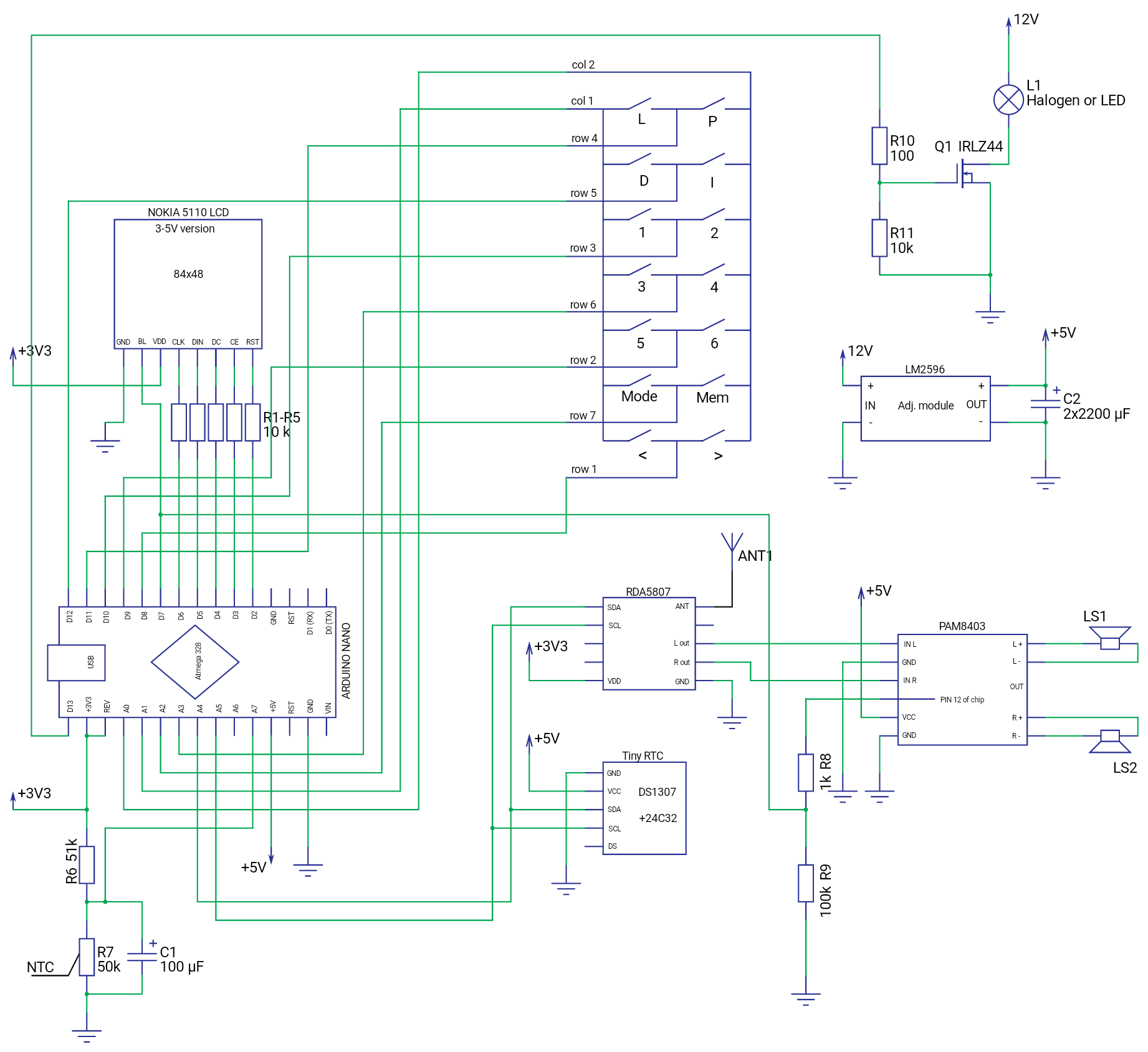
Saya memahami cara kerja panel sentuh TR028. Sebenarnya itu adalah keypad 2 kolom X 7 baris. Untuk mengoperasikannya saya menggunakan pustaka ini.
Papan yang telah dirakit ditempatkan dalam kotak. Anda dapat melihat bahwa saya telah mencabut soket USB dan mencabut kabel langsung. Itu untuk kemungkinan menghubungkan PC dan perbaikan perangkat lunak di masa depan.
Cara kerjanya:
- Radio tidak akan menyala setelah sumber daya terhubung. Ini mencegah radio memainkan jika jalur listrik tidak stabil atau listrik padam. Untuk menyala radio pertama kali Anda harus menghubungkan sumber daya dan setelah beberapa detik menekan tombol daya. Radio akan memainkan stasiun radio yang terakhir diputar dengan volume pada level 03. Mode operasi akan VOLUME kontrol. Untuk mematikan radio cukup menekan tombol daya. Perangkat akan mematikan LCD, lampu latar LCD, pemampul dan lampu LED / halogen.
- Untuk mencari stasiun radio Anda dapat memilih mode penyesuaian Auto atau Manual dengan menekan tombol "Mod". Dengan menekan tombol "<" atau ">", radio akan mencari stasiun radio dengan menurunkan atau meningkatkan frekuensi. Untuk menyimpan stasiun radio yang ditemukan tekan tombol "Mem" dan Anda akan memiliki 4 detik untuk memilih salah satu dari enam preset yang ingin Anda simpan.
- Untuk melihat tanggal saat ini tekan tombol I (info). Tanggal akan ditampilkan selama 4 detik. Bagian kode ini dapat dioptimalkan karena menggunakan fungsi delay().
- Untuk menyesuaikan jam tekan dan tahan tombol D untuk setidaknya 2 detik ketika Anda mendengar sinyal akhir jam (sinyal waktu), atau lihat detik terakhir dari jam pada beberapa jam yang akurat. Lepaskan tombol D untuk mengatur hh.00.00. Jika jam Anda terlambat dari 15 hingga 1 menit, menit dan detik akan diatur ke 00 dan jam akan ditambah 1 dan jika jam Anda terlalu cepat dari 1 hingga 15 menit, hanya menit dan detik yang akan diatur ke 00 setelah prosedur penyesuaian.
Apa yang akan saya ubah:
- Resonator pada modul RTC untuk memiliki akurasi yang lebih baik tetapi fitur penyesuaian jam memungkinkan untuk menyelesaikan masalah ini.
- LCD 5110 ke yang lebih besar dan lebih terang. Mungkin beberapa LCD warna 1,8" atau 2.0" karena terkadang sulit untuk membaca informasi pada LCD NOKIA 5110 yang digunakan dalam proyek.
- Pemampul PAM8403 ke PAM8610 yang memiliki daya keluaran 2x15W atau TDA7297 dengan karakteristik yang sama.
Kesimpulan:
Saya senang bagaimana proyek baru saya bekerja. Tidak ada masalah yang diamati setelah 1 bulan bekerja kecuali akurasi jam.
Saya bukan programmer jadi kode dapat dioptimalkan lebih baik. Pengalaman saya dalam pemrograman C/C++ sekitar satu tahun, belajar mandiri. Ini adalah proyek pertama saya yang berguna menggunakan platform Arduino dan proyek pertama yang saya bagikan di hub. Mohon pahami dan maafkan saya untuk kesalahan yang mungkin terjadi dan bahasa Inggris yang buruk saya.
Jika Anda memiliki pertanyaan jangan ragu untuk bertanya di komentar atau PM.
Update 1.: Pembaruan perangkat lunak dan perangkat keras minor.
Perangkat keras - dipasang sekring 2A pada garis 12V. Hanya untuk alasan keselamatan.
Perangkat lunak - ditambahkan baris 586 menu = 1; Ini mengembalikan mode ke VOLUME setelah menekan tombol daya.
Update 2:
Sayangnya LCD di radio saya akan mati.
Jadi saya sedang mencari alternatif LCD NOKIA 5110 yang murah. Saya tidak akan memasang LCD 5110 baru karena itu kecil dan sulit dibaca. Saya pikir saya akan bereksperimen dengan LCD TFT 1,8". Hal yang baik - itu lebih besar, lebih terang, memiliki resolusi yang lebih baik. Hal yang buruk - saya yakin LCD TFT 1,8" akan mengonsumsi lebih banyak sumber daya yang kritis.
Saran Anda mengenai penggantian LCD diterima dengan senang hati.
Kode
- Sketsa Proyek
- Simbol kekuatan sinyal
Sketsa ProyekArduino
///////////////////////////////////////////////////////////////// // Arduino based shower FM Radio Project // // Arduino NANO, RDA5807M, RTC, EEPROM, LCD5110, Thermistor // ///////////////////////////////////////////////////////////////// #include <LCD5110_Graph.h> //https://www.rinkydinkelectronics.com/library.php?id=48 #include <AT24CX.h> //https://github.com/cyberp/AT24Cx #include <Wire.h> //Arduino IDE included #include <RDSParser.h> //https://www.mathertel.de/Arduino/RadioLibrary.aspx #include <radio.h> //https://www.mathertel.de/Arduino/RadioLibrary.aspx #include <RTClib.h> //https://github.com/adafruit/RTClib #include <RDA5807M.h> //https://www.mathertel.de/Arduino/RadioLibrary.aspx #include <Keypad.h> //https://playground.arduino.cc/Code/Keypad #define MAXmenu 4 #define ledPin 13 #define blPin 7 //define the cymbols on the buttons of the keypads char keys[7][2] = { {'L', 'P'}, //LED, POWER {'I', 'D'}, //INFO, DISPLAY {'1', '2'}, //presets {'3', '4'}, //from 1 {'5', '6'}, //to 6 {'M', 'm'}, //MODE, MEM {'<', '>'} //down, up }; byte rowPins[7] = {11, 12, 10, 17, 9, 16, 8}; //connect to the row pinouts of the keypad byte colPins[2] = {15, 14}; //connect to the column pinouts of the keypad //Keypad kpd = Keypad( makeKeymap(keys), rowPins, colPins, ROWS, COLS ); Keypad keypad = Keypad( makeKeymap(keys), rowPins, colPins, 7, 2 ); boolean bass = 0, dspl = 0, memdisplay = 0, mempress = 0, adj = 0; boolean ledPin_state, power_state; int menu; int volume, volumeOld = 5; int frequency, frequencyOld; int txtl = 0, temparray = 0; int samples[5]; unsigned int status[6]; unsigned long timeprevious = 0, timeprev = 0; // EEPROM object AT24CX mem; RTC_DS1307 rtc; //(clk, din, dc, ce, rst) LCD5110 lcd(6, 5, 4, 2, 3); // Create an instance of a RDA5807 chip radio RDA5807M radio; /// get a RDS parser RDSParser rds; extern unsigned char SmallFont[]; extern uint8_t signal5[]; extern uint8_t signal4[]; extern uint8_t signal3[]; extern uint8_t signal2[]; extern uint8_t signal1[]; //--------------------------SETUP----------------------------------// void setup() { analogReference(EXTERNAL); Serial.begin(9600); Wire.begin(); // Initialize the Radio radio.init(); radio.debugEnable(); //initialize the Screen lcd.InitLCD(); lcd.clrScr(); //lcd.setContrast(45); //adjust if default isn't good lcd.setFont(SmallFont); lcd.enableSleep(); //stand-by mode power_state = 0; //don't "power-on" of the unit (stand by mode) when power supply is connected //inicialize the keyboard keypad.addStatedEventListener(keypadEvent); // Add an event listener for this keypad keypad.setHoldTime(1500); pinMode(ledPin, OUTPUT); // Sets the digital pin as output. pinMode(blPin, OUTPUT); // Sets the digital pin as output. digitalWrite(ledPin, LOW); // Turn the LED off. digitalWrite(blPin, LOW); // Turn the BL off (stand-by mode) ledPin_state = digitalRead(ledPin); // Store initial LED state. HIGH when LED is on. //uncomment if rtc need to be adjusted /*if (! rtc.isrunning()) { Serial.println("RTC is NOT running!"); // following line sets the RTC to the date & time this sketch was compiled rtc.adjust(DateTime(F(__DATE__), F(__TIME__))); // This line sets the RTC with an explicit date & time, for example to set // January 21, 2014 at 3am you would call: //rtc.adjust(DateTime(2018, 3, 13, 22, 33, 0)); }*/ // read value of last frequency frequency = mem.readInt(201); volume = 2; //volume level at start menu = 1; //shows VOLUMME mode at start if (volume < 0) volume = 0; if (volume > 15) volume = 15; if (frequency < 0) frequency = 0; if (frequency > 210) frequency = 210; WriteReg(0x02, 0xC00d); // write 0xC00d into Reg.2 ( soft reset, enable,RDS, ) //bbz canal(frequency); // setup the information chain for RDS data. radio.attachReceiveRDS(RDS_process); rds.attachServicenNameCallback(DisplayServiceName); //rds.attachTimeCallback(DisplayTime); //for future use. very inaccurate when RDS signal is weak. rds.attachTextCallback(DisplayText); } //-----------------------end of Setup------------------------------------// //--------------------------LOOP----------------------------------------// void loop() { if ( frequency != frequencyOld) { frequencyOld = frequency; mem.writeInt(201, frequency); canal(frequency); } if (volume != volumeOld) { volumeOld = volume; WriteReg(5, 0x84D0 | volume); } //read the keyboard char key = keypad.getKey(); //check for RDS data radio.checkRDS(); // reads temperature probe every 0,6 sec 5 times and calculates average float average; unsigned long timenow = millis(); if ((unsigned long)(timenow - timeprevious) > 600) { timeprevious = timenow; samples[temparray] = analogRead(A7); temparray++; } if (temparray == 5) { // calculating average of readings average = 0; for (int i = 0; i < 5; i++) { average += samples[i]; } printTemp(average); temparray = 0; } // 4 sec timeout for MEM display and enter unsigned long dabar = millis(); if (mempress == 1) { timeprev = dabar; memdisplay = 1; mempress = 0; } if (memdisplay == 1) { if ((unsigned long)(dabar - timeprev) < 4000) { memdisplay = 1; } else { memdisplay = 0; } } /*Time adjustment instructions: 1. Run serial monitor 2. Set 9600 boud 3. Hit enter to activate serial reading 4. Write hXX, where XX is current hour reading on some time server and hit enter to adjust RTC hours. Serial monitor should write "Hours XX" 5. Write mXX, where XX is current minutes reading on some time server and hit enter to adjust RTC minutes. Serial monitor should write "Minutes XX" 6. Write sXX, where XX is current seconds reading on some time server and hit enter to adjust RTC seconds. Serial monitor should write "Seconds XX" 7. You can adjust only hours. I.e. when day light saving time was changed. 8. You can adjust only seconds if you need to correct time only. 9. If RTC has to be adjusted from zero (year, month, day, etc), uncomment RTC adjustment statement lines and upload the sketch. */ DateTime now = rtc.now(); if (Serial.available() > 0) { char t = Serial.read(); switch (t) { case ('h'): { unsigned int hours = Serial.parseInt(); rtc.adjust(DateTime(now.year(), now.month(), now.day(), hours, now.minute(), now.second())); Serial.println(F("Hours")); Serial.println(hours); break; } case ('m'): { unsigned int mins = Serial.parseInt(); rtc.adjust(DateTime(now.year(), now.month(), now.day(), now.hour(), mins, now.second())); Serial.println(F("Minutes")); Serial.println(mins); break; } case ('s'): { unsigned int sec = Serial.parseInt(); rtc.adjust(DateTime(now.year(), now.month(), now.day(), now.hour(), now.minute(), sec)); Serial.println(F("Seconds")); Serial.println(sec); break; } } } //display various information on LCD printSignalStrength(); printLines(); printTime(); printFreq(); printStereo(); printMode(); printMenu(); printDate(); lcd.update(); } //------------------------End of Loop------------------------------------// void printSignalStrength() //from 0000 to 1111 (0-63) { unsigned int sig; Readstatus(); sig = status[1] / 1000; if ((sig >= 0) && (sig <= 12)) { lcd.drawBitmap(1, 1, signal1, 17 , 6); } if ((sig >= 13) && (sig <= 24)) { lcd.drawBitmap(1, 1, signal2, 17 , 6); } if ((sig >= 25) && (sig <= 36)) { lcd.drawBitmap(1, 1, signal3, 17 , 6); } if ((sig >= 37) && (sig <= 48)) { lcd.drawBitmap(1, 1, signal4, 17 , 6); } if (sig >= 49) { lcd.drawBitmap(1, 1, signal5, 17 , 6); } } void printLines() { lcd.drawLine(0, 9, 84, 9); lcd.drawLine(0, 39, 84, 39); } void printTemp(float average) //could be optimised :) { average /= 5; average = 1023 / average - 1; average = 51700 / average; float steinhart; steinhart = average / 50000; // (R/Ro) steinhart = log(steinhart); // ln(R/Ro) steinhart /= 3950; // 1/B * ln(R/Ro) steinhart += 1.0 / (25 + 273.15); // + (1/To) steinhart = 1.0 / steinhart; // invert steinhart -= 273.15; // celsius conversion int tmp = round(steinhart); lcd.printNumI(tmp, 60, 1, 2); lcd.print(F("~C"), 72, 1); } /// Update the ServiceName text on the LCD display when in RDS mode. void DisplayServiceName(char *name) { lcd.print(name, 18, 22); } void DisplayText(char *text) { //scroll second RDS line lcd.print(text, txtl, 30); txtl = txtl - 66; if (txtl == -396) txtl = 0; } void printTime() { DateTime now = rtc.now(); lcd.printNumI(now.hour(), 24, 1, 2, '0'); lcd.print(":", 36, 1); lcd.printNumI(now.minute(), 42, 1, 2, '0'); } void printDate() { if (dspl == 1) { //checks if display key was pressed ClearRDS(); DateTime now = rtc.now(); lcd.printNumI(now.year(), 12, 22, 4); lcd.print(".", 36, 22); lcd.printNumI(now.month(), 42, 22, 2, '0'); lcd.print(".", 54, 22); lcd.printNumI(now.day(), 60, 22, 2, '0'); int dw = now.dayOfTheWeek(); switch (dw) { case 0: lcd.print(F("Sekmadienis"), CENTER, 30); //sunday F() macro to save sdram break; case 1: lcd.print(F("Pirmadienis"), CENTER, 30); //monday etc... break; case 2: lcd.print(F("Antradienis"), CENTER, 30); break; case 3: lcd.print(F("Treciadienis"), CENTER, 30); break; case 4: lcd.print(F("Ketvirtadienis"), CENTER, 30); break; case 5: lcd.print(F("Penktadienis"), CENTER, 30); break; case 6: lcd.print(F("Sestadienis"), CENTER, 30); break; } lcd.update(); delay(4000); //not optimal ClearRDS(); dspl = 0; } } void printMode() { lcd.print(F("MODE "), 0, 41); } void printMenu() { if (menu == 1) { lcd.print(F("VOLUME "), 30, 41); if (volume < 0) { lcd.print(F("XX"), 72, 41); } else lcd.printNumI(volume + 1, 72, 41, 2, '0'); } if (menu == 2) { lcd.print(F("AUTO-TUNE"), 30, 41); } if (menu == 3) { lcd.print(F("MAN.-TUNE"), 30, 41); } if (menu == 4) { lcd.print(F(" BASS "), 30, 41); if (bass == 0) { lcd.print(F("OFF"), 66, 41); } else lcd.print(F(" ON"), 66, 41); } } void printFreq() //displays current frequency { int frHundr, frDec; unsigned int fr; fr = 870 + frequency; frHundr = fr / 10; frDec = fr % 10; lcd.printNumI(frHundr, 30, 12, 3); lcd.print(F("."), 48, 12); lcd.printNumI(frDec, 54, 12, 1); lcd.print(F("MHz"), 66, 12); } void printStereo() { if (memdisplay == 1) { //if MEM key was pressed lcd.print(F("MEM>"), 0, 12); } //Stereo detection else if ((status[0] & 0x0400) == 0) lcd.print(F("( )"), 0, 12); //means MONO else lcd.print (F("(ST)"), 0, 12); //means STEREO } void search(byte direc) //automatic seek { byte i; //seek up or down if (!direc) WriteReg(0x02, 0xC30d); else WriteReg(0x02, 0xC10d); for (i = 0; i < 10; i++) { delay(200); Readstatus(); if (status[0] & 0x4000) { frequency = status[0] & 0x03ff; break; } } } void canal( int canal) //direct frequency { byte numberH, numberL; numberH = canal >> 2; numberL = ((canal & 3) << 6 | 0x10); Wire.beginTransmission(0x11); Wire.write(0x03); Wire.write(numberH); // write frequency into bits 15:6, set tune bit Wire.write(numberL); Wire.endTransmission(); } //RDA5807_adrs=0x10; // I2C-Address RDA Chip for sequential Access int Readstatus() { Wire.requestFrom(0x10, 12); for (int i = 0; i < 6; i++) { status[i] = 256 * Wire.read () + Wire.read(); } Wire.endTransmission(); } //RDA5807_adrr=0x11; // I2C-Address RDA Chip for random Access void WriteReg(byte reg, unsigned int valor) { Wire.beginTransmission(0x11); Wire.write(reg); Wire.write(valor >> 8); Wire.write(valor & 0xFF); Wire.endTransmission(); //delay(50); } void RDS_process(uint16_t block1, uint16_t block2, uint16_t block3, uint16_t block4) { rds.processData(block1, block2, block3, block4); } void ClearRDS() { lcd.print(" ", 0, 22); lcd.print(" ", 0, 30); } // Taking care of some special events. void keypadEvent(KeypadEvent key, KeyState kpadState ) { switch (kpadState) { /* Another way to adjust time: 1. Press and hold key D for at least 2 sec, when you hear hour ending time signals, or see last hour seconds on some accurate clock. 2. Release key D to adjust hh.00.00. 3. Ahter adjustment, if your clock was late from 15 to 1 minutes, minutes and seconds will be 00 and hours will be increased by 1. 4. If your clock was hurry from 1 to 15 minutes, only minutes and seconds will be 00. */ case HOLD: if (key == 'D' && power_state == 1) { adj = 1; } break; case RELEASED: if (key == 'D' && adj == 1) { DateTime now = rtc.now(); if (now.minute() >= 45 && now.minute() <= 59) { rtc.adjust(DateTime(now.year(), now.month(), now.day(), now.hour() + 1, 0, 0)); } if (now.minute() >= 1 && now.minute() <= 15) { rtc.adjust(DateTime(now.year(), now.month(), now.day(), now.hour(), 0, 0)); } adj = 0; } break; case PRESSED: if (key == 'M' && power_state == 1) { memdisplay = 0; menu++; if (menu > MAXmenu)menu = 1; } if (key == '>' && power_state == 1) { memdisplay = 0; switch (menu) { case 1: if (volume < 0) { if (bass == 0) { WriteReg(0x02, 0xD00D); volume = 0; } if (bass == 1) { WriteReg(0x02, 0xC00D); volume = 0; } } else volume++; if (volume > 15)volume = 15; break; case 2: search(0); ClearRDS(); break; case 3: frequency++; if (frequency > 210)frequency = 210; // upper frequency limit ClearRDS(); break; case 4: if (bass == 0) { bass = 1; WriteReg(0x02, 0xD00D); } break; } } if (key == '<' && power_state == 1) { memdisplay = 0; switch (menu) { case 1: volume--; if (volume < 0) { WriteReg(0x02, 0x800D); //volume = 0; } break; case 2: search(1); ClearRDS(); break; case 3: frequency--; if (frequency < 0)frequency = 0; ClearRDS(); break; case 4: if (bass == 1) { bass = 0; WriteReg(0x02, 0xC00D); } break; } } // LED lights on/off if (key == 'L' && power_state == 1) { digitalWrite(ledPin, !digitalRead(ledPin)); ledPin_state = digitalRead(ledPin); // Remember LED state, lit or unlit. } // turns "power" on or off (stand-by mode) if (key == 'P') { digitalWrite(blPin, !digitalRead(blPin)); power_state = digitalRead(blPin); if (power_state == 0) { lcd.enableSleep(); digitalWrite(ledPin, LOW); } else lcd.disableSleep(); volume = 2; menu = 1; } if (key == '1' && power_state == 1) { switch (memdisplay) { case 0: frequency = mem.readInt(110); ClearRDS(); break; case 1: mem.writeInt(110, frequency); memdisplay = 0; break; } } if (key == '2' && power_state == 1) { switch (memdisplay) { case 0: frequency = mem.readInt(120); ClearRDS(); break; case 1: mem.writeInt(120, frequency); memdisplay = 0; break; } } if (key == '3' && power_state == 1) { switch (memdisplay) { case 0: frequency = mem.readInt(130); ClearRDS(); break; case 1: mem.writeInt(130, frequency); memdisplay = 0; break; } } if (key == '4' && power_state == 1) { switch (memdisplay) { case 0: frequency = mem.readInt(140); ClearRDS(); break; case 1: mem.writeInt(140, frequency); memdisplay = 0; break; } } if (key == '5' && power_state == 1) { switch (memdisplay) { case 0: frequency = mem.readInt(150); ClearRDS(); break; case 1: mem.writeInt(150, frequency); memdisplay = 0; break; } } if (key == '6' && power_state == 1) { switch (memdisplay) { case 0: frequency = mem.readInt(160); ClearRDS(); break; case 1: mem.writeInt(160, frequency); memdisplay = 0; break; } } if (key == 'm' && power_state == 1) { mempress = 1; } else { mempress = 0; } if (key == 'I' && power_state == 1) { dspl = 1; } break; } } Signal strenght symbolsC/C++
#if defined(__AVR__) #include <avr/pgmspace.h> #define imagedatatype const uint8_t #elif defined(__PIC32MX__) #define PROGMEM #define imagedatatype const unsigned char #elif defined(__arm__) #define PROGMEM #define imagedatatype const unsigned char #endif imagedatatype signal5[] PROGMEM={ 0xC1, 0xC2, 0xC4, 0xFF, 0xC4, 0xC2, 0xC1, 0xC0, 0xE0, 0xC0, 0xF0, 0xC0, 0xF8, 0xC0, 0xFC, 0xC0, // 0x0010 (16) pixels 0xFE, }; imagedatatype signal4[] PROGMEM={ 0xC1, 0xC2, 0xC4, 0xFF, 0xC4, 0xC2, 0xC1, 0xC0, 0xE0, 0xC0, 0xF0, 0xC0, 0xF8, 0xC0, 0xFC, 0xC0, // 0x0010 (16) pixels 0xC0, }; imagedatatype signal3[] PROGMEM={ 0xC1, 0xC2, 0xC4, 0xFF, 0xC4, 0xC2, 0xC1, 0xC0, 0xE0, 0xC0, 0xF0, 0xC0, 0xF8, 0xC0, 0xC0, 0xC0, // 0x0010 (16) pixels 0xC0, }; imagedatatype signal2[] PROGMEM={ 0xC1, 0xC2, 0xC4, 0xFF, 0xC4, 0xC2, 0xC1, 0xC0, 0xE0, 0xC0, 0xF0, 0xC0, 0xC0, 0xC0, 0xC0, 0xC0, // 0x0010 (16) pixels 0xC0, }; imagedatatype signal1[] PROGMEM={ 0xC1, 0xC2, 0xC4, 0xFF, 0xC4, 0xC2, 0xC1, 0xC0, 0xE0, 0xC0, 0xC0, 0xC0, 0xC0, 0xC0, 0xC0, 0xC0, // 0x0010 (16) pixels 0xC0, };
Skematik