Panduan Lengkap Modbus pada Arduino: Langkah demi Langkah
Komponen dan Perlengkapan
Arduino UNO
Shield RS422 / RS485 Professional untuk Arduino
Konverter USB-to-RS485
Breadboard (generik)
LED (generik)
Resistor 10k ohm
Resistor 221 ohm
Kabel jumper (generik)
Tombol saklar SparkFun Pushbutton 12mm
Aplikasi dan Layanan Online
Arduino IDE
Modbustester
Tentang Proyek Ini
Modbus, standar komunikasi serial, telah menjadi protokol komunikasi de facto dan sekarang merupakan sarana umum untuk menghubungkan perangkat elektronik industri. Dalam Modbus RTU dan Modbus ASCII, RS485 digunakan sebagai lapisan fisik. Arduino dapat digunakan sebagai slave (dan dengan beberapa keterbatasan juga sebagai master) dalam aplikasi Modbus, tetapi antarmuka RS485 diperlukan. Shield RS422 / RS485 kami adalah shield komunikasi serial yang terisolasi galvanik sepenuhnya, dirancang untuk Arduino UNO dan papan kompatibel lainnya seperti Arduino 101, STM Nucleo... Shield ini adalah pilihan yang sempurna untuk aplikasi ini.
Tujuan dokumen ini adalah menunjukkan cara membuat perangkat slave Modbus sederhana bersama Arduino UNO. Kami akan menggunakan PC sebagai Modbus master.
Alat dan Bahan
Arduino UNO
Shield RS485 untuk Arduino
Adaptor RS485-USB apa pun untuk koneksi PC (atau yang lebih murah)
Opsional:
Breadboard
Tombol push
LED merah
Resistor 220 Ohm
Resistor 10k
Kabel jumper
Perangkat Lunak
Arduino IDE
Modbustester
Pengkabelan RS485
Pengkabelannya sangat sederhana. Anda hanya perlu menghubungkan terminal A dan B shield dengan garis A dan B sistem Modbus. Terminal Y dan Z tidak digunakan untuk jenis aplikasi ini. Untuk jarak jauh, disarankan menggunakan kabel pasir terbalik (twisted pairs) untuk A dan B.
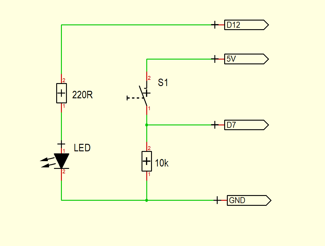
Pengkabelan Arduino (Opsional)
Disarankan menambahkan LED dan tombol pada Arduino untuk melihat efek komunikasi Modbus. Ini opsional dan tidak wajib.
Pengaturan DIP Switch
Shield RS422/RS485 dilengkapi dengan 3 bank DIP switch. Anda harus mengatur DIP switch ini untuk Modbus seperti yang ditunjukkan dalam gambar di bawah ini.
Switch 1: 1-OFF 2-ON 3-ON 4-OFF
Switch 2: 1-OFF 2-OFF 3-ON 4-ON
Switch 3: 1-OFF atau ON* 2-OFF 3-OFF 4-OFF
*Bergantung pada posisi Shield RS422/RS485 pada garis Modbus, Anda harus mengaktifkan atau menonaktifkan resistor terminasi. Aktifkan resistor ke posisi ON hanya jika Shield berada di salah satu ujung garis bus. Dalam semua kasus lain, nonaktifkan resistor terminasi:
Pengaturan Jumper
Anda dapat menemukan 3 area jumper berbeda pada shield. Sangat penting adalah Jumper JP1 untuk tegangan daya. Arduino UNO bekerja dengan 5V secara internal. Anda harus mengatur Jumper ini ke posisi 5V (untuk papan 3.3V misalnya Arduino 101 ke posisi 3.3V).
Selanjutnya atur jumper untuk port komunikasi di sudut kiri atas seperti dalam gambar di atas. UART internal pada port 0 dan 1 akan terhubung ke antarmuka RS485 shield.
Terakhir, kita harus mengatur Jumper untuk port kontrol RX/TX. Kami tidak menggunakan Jumper ini, karena pengalihan RX/TX otomatis sudah dikonfigurasi.
Instalasi Perangkat Lunak Modbus Tester di PC
Dalam contoh ini kami akan menggunakan PC sebagai Modbus master. Anda harus mengunduh Modbustester. Ekstrak arsip zip ke direktori baru pada harddisk Anda. Buka perangkat lunak dan ubah field yang ditandai seperti dalam gambar di bawah ini. Anda harus menghubungkan adaptor USB-RS485 terlebih dahulu—Harap pilih port COM yang benar untuk adaptor ini di Modbustester.
Perangkat Lunak Arduino
Silakan muat firmware ke Arduino IDE untuk dikompilasi dan diprogram.
Uji Kerja Anda
Sekarang saatnya untuk menguji pekerjaan Anda!
Anda dapat menekan tombol Read di Modbustester. Perintah ini akan membaca 8 byte memori dari perangkat slave baru kita. Di alamat 400008 Anda dapat menemukan status tombol. Alamat 400001 - 400006 berisi nilai port ADC.
Dengan tombol write Anda dapat memanipulasi register di slave. Anda dapat memasukkan 0 atau 1 di alamat 400007 untuk menyalakan atau mematikan LED.
Kode
Contoh kode untuk Arduino UNO
Contoh kode untuk Arduino UNOArduino
/* * Test program for Arduino RS422/RS485 Shield * Version 1.0 * Copyright (C) 2018 Hartmut Wendt www.zihatec.de * * (based on sources of https://github.com/angeloc/simplemodbusng) * * * This program is free software: you can redistribute it and/or modify * it under the terms of the GNU General Public License as published by * the Free Software Foundation, either version 3 of the License, or * (at your option) any later version. * * This program is distributed in the hope that it will be useful, * but WITHOUT ANY WARRANTY; without even the implied warranty of * MERCHANTABILITY or FITNESS FOR A PARTICULAR PURPOSE. See the * GNU General Public License for more details. * * You should have received a copy of the GNU General Public License * along with this program. If not, see <https://www.gnu.org/licenses/>. */ #include <SimpleModbusSlave.h> #define ledPin 12 // onboard led #define buttonPin 7 // push button /* This example code has 9 holding registers. 6 analogue inputs, 1 button, 1 digital output and 1 register to indicate errors encountered since started. Function 5 (write single coil) is not implemented so I'm using a whole register and function 16 to set the onboard Led on the Atmega328P. The modbus_update() method updates the holdingRegs register array and checks communication. Note: The Arduino serial ring buffer is 128 bytes or 64 registers. Most of the time you will connect the arduino to a master via serial using a MAX485 or similar. In a function 3 request the master will attempt to read from your slave and since 5 bytes is already used for ID, FUNCTION, NO OF BYTES and two BYTES CRC the master can only request 122 bytes or 61 registers. In a function 16 request the master will attempt to write to your slave and since a 9 bytes is already used for ID, FUNCTION, ADDRESS, NO OF REGISTERS, NO OF BYTES and two BYTES CRC the master can only write 118 bytes or 59 registers. Using the FTDI USB to Serial converter the maximum bytes you can send is limited to its internal buffer which is 60 bytes or 30 unsigned int registers. Thus: In a function 3 request the master will attempt to read from your slave and since 5 bytes is already used for ID, FUNCTION, NO OF BYTES and two BYTES CRC the master can only request 54 bytes or 27 registers. In a function 16 request the master will attempt to write to your slave and since a 9 bytes is already used for ID, FUNCTION, ADDRESS, NO OF REGISTERS, NO OF BYTES and two BYTES CRC the master can only write 50 bytes or 25 registers. Since it is assumed that you will mostly use the Arduino to connect to a master without using a USB to Serial converter the internal buffer is set the same as the Arduino Serial ring buffer which is 128 bytes. */ // Using the enum instruction allows for an easy method for adding and // removing registers. Doing it this way saves you #defining the size // of your slaves register array each time you want to add more registers // and at a glimpse informs you of your slaves register layout. //////////////// registers of your slave /////////////////// enum { // just add or remove registers and your good to go... // The first register starts at address 0 ADC0, ADC1, ADC2, ADC3, ADC4, ADC5, LED_STATE, BUTTON_STATE, TOTAL_ERRORS, // leave this one TOTAL_REGS_SIZE // total number of registers for function 3 and 16 share the same register array }; unsigned int holdingRegs[TOTAL_REGS_SIZE]; // function 3 and 16 register array //////////////////////////////////////////////////////////// void setup() { /* parameters(long baudrate, unsigned char ID, unsigned char transmit enable pin, unsigned int holding registers size, unsigned char low latency) The transmit enable pin is used in half duplex communication to activate a MAX485 or similar to deactivate this mode use any value < 2 because 0 & 1 is reserved for Rx & Tx. Low latency delays makes the implementation non-standard but practically it works with all major modbus master implementations. */ modbus_configure(9600, 1, 6, TOTAL_REGS_SIZE, 0); pinMode(ledPin, OUTPUT); pinMode(buttonPin, INPUT); } void loop() { // modbus_update() is the only method used in loop(). It returns the total error // count since the slave started. You don't have to use it but it's useful // for fault finding by the modbus master. holdingRegs[TOTAL_ERRORS] = modbus_update(holdingRegs); for (byte i = 0; i < 6; i++) { holdingRegs[i] = analogRead(i); delayMicroseconds(50); } byte buttonState = digitalRead(buttonPin); // read button states // assign the buttonState value to the holding register holdingRegs[BUTTON_STATE] = buttonState; // read the LED_STATE register value and set the onboard LED high or low with function 16 byte ledState = holdingRegs[LED_STATE]; if (ledState) // set led { digitalWrite(ledPin, HIGH); } else if (ledState == 0) // reset led { //digitalWrite(ledPin, LOW); holdingRegs[LED_STATE] = 0; } }