Membangun Kubus LED RGB 8x8x8 dengan Arduino – Panduan DIY
Komponen dan Perlengkapan
RGB Diffused Common Anode
×
512
Driver LED DM13A
×
12
74HC138 3 to 8 line decod
×
1
MOSFET P-Channel IRF9640
×
8
Arduino UNO
Anda juga dapat membuat versi breadboard dengan hanya ATmega328, kristal 16Mhz, 2 x kapasitor 22pf
×
1
Digilent 5V 2.5A Switching Power Supply
×
1
Resistor 10k ohm
×
8
Resistor 1k ohm
×
8
Resistor 100 ohm
×
8
Aplikasi dan Layanan Online
Arduino IDE
Tentang Proyek Ini
VideoBuild
Build ini terinspirasi dari kubus RGB Kevin Darrah.
Melihat build Kevin, kesabarannya pasti tidak terbatas - sayangnya milik saya terbatas.
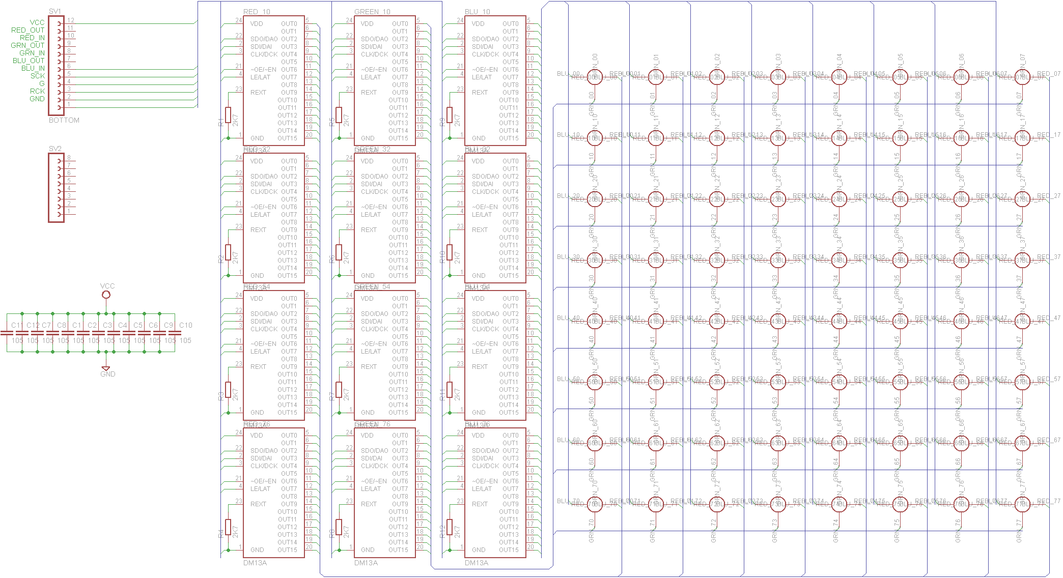
Saya memutuskan untuk mengganti 24 shift register, 192 transistor dan 640 resistor dengan 12 driver LED DM13a (sekitar $1 US per satu di eBay).
Kubus itu sendiri dibangun seperti yang Kevin jelaskan dalam video berikut:
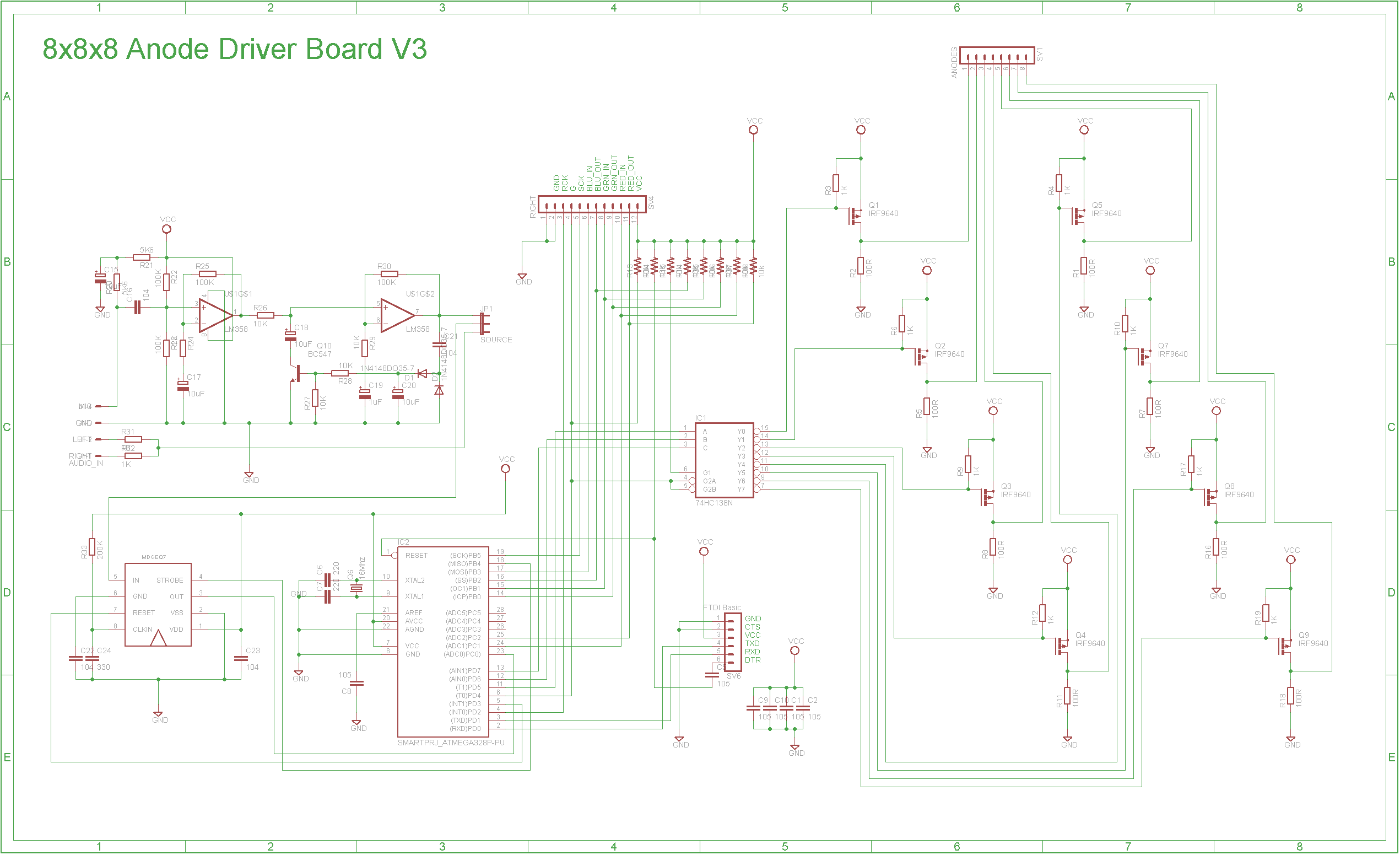
Setelah kubus selesai, saya membuat papan sirkuit cetak menggunakan metode Toner untuk menahan chip driver DM13A dan kubus itu sendiri. Alih-alih membayar biaya papan yang dibuat secara komersial dengan plating lubang melalui, saya memutuskan untuk menyambungkan setiap sambungan LED secara manual ke pin DM13A yang sesuai menggunakan kawat wire-wrap. File Eagle yang disertakan berisi versi yang disambung manual serta versi auto-routed (belum diuji).
Mikroprosesor dan papan anode juga menahan MSGEQ7 - Seven Band Graphic Equalizer dan pre-amp mikrofon yang rencananya akan saya bereksperimen di masa depan. Saat ini, mereka tidak digunakan. Jika Anda ingin menggunakan board UNO atau Nano komersial, yang Anda butuhkan hanyalah 74HC138 3 to 8 line decoder dan 8 MOSFET P-Channel serta resistor yang terkait. Anda dapat menyambungkannya pada papan proto jika Anda mau.
Suplai daya 5V 20W dibeli di eBay. Saya membuat kotak dari kayu pine 40mm x 9mm yang telah diresapkan.
Saya menambahkan beberapa animasi ke software kubus Kevin tetapi pada dasarnya tetap tidak berubah.
Kesimpulan
Anda seharusnya dapat membeli 600 x 5mm Common Anode difused RGB LEDs dari eBay untuk sekitar $30 US. Bahkan setelah menyederhanakan elektronika, pembangunan kubus sangat memakan waktu tetapi pada akhirnya, memberikan rasa puas.
Kode
Cube_8x8x8_V1.ino
Cube_8x8x8_V1.inoC/C++
/* The 8x8x8 RGB LED Cube by John Bradnam based on work by Kevin Darrah Latest V12 04/17/2013 Release Notes: V11 - Fixed bug with BAM timing - Moved Blank pin setup to ISR so pins are dead until they are written to V12 bitwise operation to set pins LOW was incorrect should be PORTx &= ~(1<<pinNumber); Disclaimer: Not a professional LED cube builder, this is how I did it, and this is my cube */ #include <SPI.h>// SPI Library used to clock data out to the shift registers #define LATCH_PIN 2 //can use any pin you want to latch the shift registers #define BLANK_PIN 4 // same, can use any pin you want for this, just make sure you pull up via a 1k to 5V #define DATA_PIN 11 // used by SPI, must be pin 11 #define CLOCK_PIN 13 // used by SPI, must be 13 #define LAYER_A 5 //74138 A Input #define LAYER_B 6 //74138 A Input #define LAYER_C 7 //74138 A Input #define SWITCH_PGM 10 //PB2 #define SWITCH_SEQ 9 //PB1 #define CUBE_SIZE 8 //Number of columns, rows or levels in cube #define CUBE_MAX (CUBE_SIZE - 1) //Max cube index #define LEDS_PER_LEVEL (CUBE_SIZE * CUBE_SIZE) //Number of LEDS per level //***variables***variables***variables***variables***variables***variables***variables***variables //These variables are used by multiplexing and Bit Angle Modulation Code //This is how the brightness for every LED is stored, //Each LED only needs a 'bit' to know if it should be ON or OFF, so 64 Bytes gives you 512 bits= 512 LEDs //Since we are modulating the LEDs, using 4 bit resolution, each color has 4 arrays containing 64 bits each byte red0[LEDS_PER_LEVEL], red1[LEDS_PER_LEVEL], red2[LEDS_PER_LEVEL], red3[LEDS_PER_LEVEL]; byte blue0[LEDS_PER_LEVEL], blue1[LEDS_PER_LEVEL], blue2[LEDS_PER_LEVEL], blue3[LEDS_PER_LEVEL]; byte green0[LEDS_PER_LEVEL], green1[LEDS_PER_LEVEL], green2[LEDS_PER_LEVEL], green3[LEDS_PER_LEVEL]; //notice how more resolution will eat up more of your precious RAM int level=0;//keeps track of which level we are shifting data to int anodeLevel=0;//this increments through the anode levels int BAM_Bit, BAM_Counter=0; // Bit Angle Modulation variables to keep track of things int animation = 0; //Keeps track of animation in main loop //****setup****setup****setup****setup****setup****setup****setup****setup****setup****setup****setup****setup****setup void setup() { SPI.setBitOrder(MSBFIRST);//Most Significant Bit First SPI.setDataMode(SPI_MODE0);// Mode 0 Rising edge of data, keep clock low SPI.setClockDivider(SPI_CLOCK_DIV2);//Run the data in at 16MHz/2 - 8MHz //Serial.begin(115200);// if you need it? noInterrupts();// kill interrupts until everybody is set up //We use Timer 1 to refresh the cube TCCR1A = B00000000;//Register A all 0's since we're not toggling any pins TCCR1B = B00001011;//bit 3 set to place in CTC mode, will call an interrupt on a counter match //bits 0 and 1 are set to divide the clock by 64, so 16MHz/64=250kHz TIMSK1 = B00000010;//bit 1 set to call the interrupt on an OCR1A match OCR1A=30; // you can play with this, but I set it to 30, which means: //our clock runs at 250kHz, which is 1/250kHz = 4us //with OCR1A set to 30, this means the interrupt will be called every (30+1)x4us=124us, // which gives a multiplex frequency of about 8kHz //finally set up the Outputs pinMode(LATCH_PIN, OUTPUT);//Latch pinMode(DATA_PIN, OUTPUT);//MOSI DATA pinMode(CLOCK_PIN, OUTPUT);//SPI Clock pinMode(LAYER_A, OUTPUT);//74138 A Input pinMode(LAYER_B, OUTPUT);//74138 B Input pinMode(LAYER_C, OUTPUT);//74138 C Input digitalWrite(LAYER_A, LOW); digitalWrite(LAYER_B, LOW); digitalWrite(LAYER_C, LOW); pinMode(SWITCH_PGM, INPUT);//PGM 1 / PGM 2 Switch pinMode(SWITCH_SEQ, INPUT);//SEQ/COLOR Switch //pinMode(BLANK_PIN, OUTPUT);//Output Enable important to do this last, so LEDs do not flash on boot up SPI.begin();//start up the SPI library interrupts();//let the show begin, this lets the multiplexing start } //***start loop***start loop***start loop***start loop***start loop***start loop***start loop***start loop***start loop void loop() { //Each animation located in a sub routine // To control an LED, you simply: // LED(level you want 0-CUBE_MAX, row you want 0-CUBE_MAX, column you want 0-CUBE_MAX, red brighness 0-15, green brighness 0-15, blue brighness 0-15); if (digitalRead(SWITCH_PGM) == HIGH) test_leds(); else { clean(); animation = animation + 1; switch (animation) { case 1: rainVersionTwo(20); break; case 2: folder(10); break; case 3: sinwaveTwo(15); break; case 4: randomColor(10); break; case 5: wipe_out(10); break; case 6: bouncyvTwo(15); break; case 7: color_wheelTWO(10); break; case 8: harlem_shake(); break; case 9: ripples(10); break; case 10: animation = 0; break; } } } //****LED Routine****LED Routine****LED Routine****LED Routine void LED(int level, int row, int column, byte red, byte green, byte blue) { //This is where it all starts //This routine is how LEDs are updated, with the inputs for the LED location and its R G and B brightness levels // First, check and make sure nothing went beyond the limits, just clamp things at either 0 or 7 for location, and 0 or 15 for brightness level = constrain(level, 0, CUBE_MAX); row = constrain(row, 0, CUBE_MAX); column = constrain(column, 0, CUBE_MAX); red = constrain(red, 0, 15); green = constrain(green, 0, 15); blue = constrain(blue, 0, 15); //There are (CUBE_SIZE * CUBE_SIZE * CUBE_SIZE) LEDs in the cube, so when we write to level 2, column 5, row 4, that needs to be translated into a number from 0 to (CUBE_SIZE * CUBE_SIZE * CUBE_SIZE) - 1 //The first level LEDs are first in the sequence, then 2nd level, then third, and so on //For a 4 x 4 x 4 cube the (level * (4 * 4)) is what indexes the level's starting place, so level 0 are LEDs 0 - 15, level 1 are LEDs 16 - 31, and so on //if you looked down on the cube, and only looked at the bottom level // 00 01 02 03 // 04 05 06 07 // 08 09 10 11 // 12 13 14 15 //For a 8 x 8 x 8 cube the (level * (8 * 8)) is what indexes the level's starting place, so level 0 are LEDs 0 - 63, level 1 are LEDs 64 - 127, and so on //if you looked down on the cube, and only looked at the bottom level // 00 01 02 03 04 05 06 07 // 08 09 10 11 12 13 14 15 // 16 17 18 19 20 21 22 23 // 24 25 26 27 28 29 30 31 // 32 33 34 35 36 37 38 39 // 40 41 42 43 44 45 46 47 // 48 49 50 51 52 53 54 55 // 56 57 58 59 60 61 62 63 //Then, if you incremented the level, the top right of the grid above would start at (CUBE_SIZE * CUBE_SIZE) //The reason for doing this, is so you don't have to memorize a number for each LED, allowing you to use level, row, column //Now, what about the divide by 8 in there? //...well, we have 8 bits per byte, and we have 64 bytes in memory for all 512 bits needed for each LED, so //we divide the number we just found by 8, and take the integer of it, so we know which byte, that bit is located //confused? that's ok, let's take an example, if we wanted to write to the LED to the last LED in the cube, we would write a 7, 7, 7 // giving (7*64)+(7*8)=7 = 511, which is right, but now let's divide it by 8, 511/8 = 63.875, and take the int of it so, we get 63, //this is the last byte in the array, which is right since this is the last LED // Get the LED number 0 - 511 int wholebyte = (level * LEDS_PER_LEVEL) + (row * CUBE_SIZE) + column; // Get the index into the array. Each indexed location holds one byte or 8 bits; int whichbyte = int(wholebyte / 8); int whichbit = (wholebyte & 7); //This will all make sense in a sec //This is 4 bit color resolution, so each color contains x4 64 byte arrays, explanation below: bitWrite(red0[whichbyte], whichbit, bitRead(red, 0)); bitWrite(red1[whichbyte], whichbit, bitRead(red, 1)); bitWrite(red2[whichbyte], whichbit, bitRead(red, 2)); bitWrite(red3[whichbyte], whichbit, bitRead(red, 3)); bitWrite(green0[whichbyte], whichbit, bitRead(green, 0)); bitWrite(green1[whichbyte], whichbit, bitRead(green, 1)); bitWrite(green2[whichbyte], whichbit, bitRead(green, 2)); bitWrite(green3[whichbyte], whichbit, bitRead(green, 3)); bitWrite(blue0[whichbyte], whichbit, bitRead(blue, 0)); bitWrite(blue1[whichbyte], whichbit, bitRead(blue, 1)); bitWrite(blue2[whichbyte], whichbit, bitRead(blue, 2)); bitWrite(blue3[whichbyte], whichbit, bitRead(blue, 3)); //Are you now more confused? You shouldn't be! It's starting to make sense now. Notice how each line is a bitWrite, which is, //bitWrite(the byte you want to write to, the bit of the byte to write, and the 0 or 1 you want to write) //This means that the 'whichbyte' is the byte from 0-63 in which the bit corresponding to the LED from 0-511 //Is making sense now why we did that? taking a value from 0-511 and converting it to a value from 0-63, since each LED represents a bit in //an array of 64 bytes. //Then next line is which bit 'wholebyte-(8*whichbyte)' //This is simply taking the LED's value of 0-511 and subracting it from the BYTE its bit was located in times 8 //Think about it, byte 63 will contain LEDs from 504 to 511, so if you took 505-(8*63), you get a 1, meaning that, //LED number 505 is is located in bit 1 of byte 63 in the array //is that it? No, you still have to do the bitRead of the brightness 0-15 you are trying to write, //if you wrote a 15 to RED, all 4 arrays for that LED would have a 1 for that bit, meaning it will be on 100% //This is why the four arrays read 0-4 of the value entered in for RED, GREEN, and BLUE //hopefully this all makes some sense? } //***MultiPlex BAM***MultiPlex BAM***MultiPlex BAM***MultiPlex BAM***MultiPlex BAM***MultiPlex BAM***MultiPlex BAM ISR(TIMER1_COMPA_vect) { //This routine is called in the background automatically at frequency set by OCR1A //In this code, I set OCR1A to 30, so this is called every 124us, giving each level in the cube 124us of ON time //There are 8 levels, so we have a maximum brightness of 1/8, since the level must turn off before the next level is turned on //The frequency of the multiplexing is then 124us*8=992us, or 1/992us= about 1kHz PORTD |= 1 << BLANK_PIN; //The first thing we do is turn all of the LEDs OFF, by writing a 1 to the blank pin //Note, in my bread-boarded version, I was able to move this way down in the cube, meaning that the OFF time was minimized //do to signal integrity and parasitic capcitance, my rise/fall times, required all of the LEDs to first turn off, before updating //otherwise you get a ghosting effect on the previous level //This is 4 bit 'Bit angle Modulation' or BAM, There are 8 levels, so when a '1' is written to the color brightness, //each level will have a chance to light up for 1 cycle, the BAM bit keeps track of which bit we are modulating out of the 4 bits //Bam counter is the cycle count, meaning as we light up each level, we increment the BAM_Counter if (BAM_Counter == (CUBE_SIZE * 1)) BAM_Bit++; else if (BAM_Counter == (CUBE_SIZE * 3)) BAM_Bit++; else if (BAM_Counter == (CUBE_SIZE * 7)) BAM_Bit++; BAM_Counter++;//Here is where we increment the BAM counter int bytes_per_level = LEDS_PER_LEVEL / 8; int shift_max = level + bytes_per_level; switch (BAM_Bit) { //The BAM bit will be a value from 0-3, and only shift out the arrays corresponding to that bit, 0-3 //Here's how this works, each case is the bit in the Bit angle modulation from 0-4, //Next, it depends on which level we're on, so the byte in the array to be written depends on which level, //For 8x8x8 each level contains 64 LED, we only shift out 8 bytes for each color //For 4x4x4 each level contains 16 LED, we only shift out 2 bytes for each color case 0: for (int shift_out = level; shift_out < shift_max; shift_out++) SPI.transfer(blue0[shift_out]); for (int shift_out = level; shift_out < shift_max; shift_out++) SPI.transfer(green0[shift_out]); for (int shift_out = level; shift_out < shift_max; shift_out++) SPI.transfer(red0[shift_out]); break; case 1: for (int shift_out = level; shift_out < shift_max; shift_out++) SPI.transfer(blue1[shift_out]); for (int shift_out = level; shift_out < shift_max; shift_out++) SPI.transfer(green1[shift_out]); for (int shift_out = level; shift_out < shift_max; shift_out++) SPI.transfer(red1[shift_out]); break; case 2: for (int shift_out = level; shift_out < shift_max; shift_out++) SPI.transfer(blue2[shift_out]); for (int shift_out = level; shift_out < shift_max; shift_out++) SPI.transfer(green2[shift_out]); for (int shift_out = level; shift_out < shift_max; shift_out++) SPI.transfer(red2[shift_out]); break; case 3: for (int shift_out = level; shift_out < shift_max; shift_out++) SPI.transfer(blue3[shift_out]); for (int shift_out = level; shift_out < shift_max; shift_out++) SPI.transfer(green3[shift_out]); for (int shift_out = level; shift_out < shift_max; shift_out++) SPI.transfer(red3[shift_out]); //Here is where the BAM_Counter is reset back to 0, it's only 4 bit, but since each cycle takes 8 counts, //, it goes 0 8 16 32, and when BAM_counter hits 64 we reset the BAM if (BAM_Counter == (CUBE_SIZE * 15)) { BAM_Counter=0; BAM_Bit=0; } break; }//switch_case //SPI.transfer(anode[anodeLevel]);//finally, send out the anode level byte digitalWrite(LAYER_A, bitRead(anodeLevel, 0)); digitalWrite(LAYER_B, bitRead(anodeLevel, 1)); digitalWrite(LAYER_C, bitRead(anodeLevel, 2)); PORTD |= 1<<LATCH_PIN;//Latch pin HIGH PORTD &= ~(1<<LATCH_PIN);//Latch pin LOW PORTD &= ~(1<<BLANK_PIN);//Blank pin LOW to turn on the LEDs with the new data anodeLevel = (anodeLevel + 1) & (CUBE_MAX); //inrement the anode level level = (level + bytes_per_level) & (LEDS_PER_LEVEL - 1); //increment the level variable by 8, which is used to shift out data, since the next level would be the next 8 bytes in the arrays pinMode(BLANK_PIN, OUTPUT); //moved down here so outputs are all off until the first call of this function } //*+*+*+*+*+*+*+*+*+*+*+*+PUT ANIMATIONS DOWN HERE*+*+*+*+*+*+*+*+*+*+*+*+PUT ANIMATIONS DOWN HERE*+*+*+*+*+*+*+*+*+*+*+*+PUT ANIMATIONS DOWN HERE //*+*+*+*+*+*+*+*+*+*+*+*+PUT ANIMATIONS DOWN HERE*+*+*+*+*+*+*+*+*+*+*+*+PUT ANIMATIONS DOWN HERE*+*+*+*+*+*+*+*+*+*+*+*+PUT ANIMATIONS DOWN HERE //*+*+*+*+*+*+*+*+*+*+*+*+PUT ANIMATIONS DOWN HERE*+*+*+*+*+*+*+*+*+*+*+*+PUT ANIMATIONS DOWN HERE*+*+*+*+*+*+*+*+*+*+*+*+PUT ANIMATIONS DOWN HERE //*+*+*+*+*+*+*+*+*+*+*+*+PUT ANIMATIONS DOWN HERE*+*+*+*+*+*+*+*+*+*+*+*+PUT ANIMATIONS DOWN HERE*+*+*+*+*+*+*+*+*+*+*+*+PUT ANIMATIONS DOWN HERE //*****test_leds*****test_leds*****test_leds*****test_leds*****test_leds*****test_leds*****test_leds*****test_leds void test_leds() { clean(); delay(1000); fill(15, 0, 0); delay(1000); fill(0, 15, 0); delay(1000); fill(0, 0, 15); delay(1000); } //*****wipe_out*****wipe_out*****wipe_out*****wipe_out*****wipe_out*****wipe_out*****wipe_out*****wipe_out void wipe_out(int runtimeInSeconds) { int fx=random(CUBE_SIZE), fy=random(CUBE_SIZE), fz=random(CUBE_SIZE), fxm=1, fym=1, fzm=1, fxo=0, fyo=0, fzo=0; int ftx=random(CUBE_SIZE), fty=random(CUBE_SIZE), ftz=random(CUBE_SIZE), ftxm=1, ftym=1, ftzm=1, ftxo=0, ftyo=0, ftzo=0; int rr, gg, bb, rrt, ggt, bbt; switch(random(3)) { case 0: rr=random(1, 16); gg=random(1, 16); bb=0; break; case 1: rr=random(1, 16); gg=0; bb=random(1, 16); break; case 2: rr=0; gg=random(1, 16); bb=random(1, 16); break; } switch (random(3)) { case 0: rrt=random(1, 16); ggt=random(1, 16); bbt=0; break; case 1: rrt=random(1, 16); ggt=0; bbt=random(1, 16); break; case 2: rrt=0; ggt=random(1, 16); bbt=random(1, 16); break; } unsigned long endTime = millis() + (runtimeInSeconds * 1000); while (millis() < endTime) { //fx=random(8); fy=random(8); fz=random(8); LED(fxo, fyo, fzo, 0, 0, 0); LED(fxo, fyo, fzo+1, 0, 0, 0); LED(fxo, fyo, fzo-1, 0, 0, 0); LED(fxo+1, fyo, fzo, 0, 0, 0); LED(fxo-1, fyo, fzo, 0, 0, 0); LED(fxo, fyo+1, fzo, 0, 0, 0); LED(fxo, fyo-1, fzo, 0, 0, 0); LED(ftxo, ftyo, ftzo, 0, 0, 0); LED(ftxo, ftyo, ftzo+1, 0, 0, 0); LED(ftxo, ftyo, ftzo-1, 0, 0, 0); LED(ftxo+1, ftyo, ftzo, 0, 0, 0); LED(ftxo-1, ftyo, ftzo, 0, 0, 0); LED(ftxo, ftyo+1, ftzo, 0, 0, 0); LED(ftxo, ftyo-1, ftzo, 0, 0, 0); LED(ftx, fty, ftz, rr, gg, bb); LED(ftx, fty, ftz+1, rr, gg, bb); LED(ftx, fty, ftz-1, rr, gg, bb); LED(ftx+1, fty, ftz, rr, gg, bb); LED(ftx-1, fty, ftz, rr, gg, bb); LED(ftx, fty+1, ftz, rr, gg, bb); LED(ftx, fty-1, ftz, rr, gg, bb); LED(fx, fy, fz, rrt, ggt, bbt); LED(fx, fy, fz+1, rrt, ggt, bbt); LED(fx, fy, fz-1, rrt, ggt, bbt); LED(fx+1, fy, fz, rrt, ggt, bbt); LED(fx-1, fy, fz, rrt, ggt, bbt); LED(fx, fy+1, fz, rrt, ggt, bbt); LED(fx, fy-1, fz, rrt, ggt, bbt); delay(10); fxo=fx; fyo=fy; fzo=fz; ftxo=ftx; ftyo=fty; ftzo=ftz; switch (random(3)) { case 0: fx = fx + fxm; if (fx < 0) { fx = 0; fxm = 1; } if (fx >= CUBE_SIZE) { fx = CUBE_MAX; fxm = -1; } break; case 1: fy = fy + fym; if (fy < 0) { fy = 0; fym = 1; } if (fy >= CUBE_SIZE) { fy = CUBE_MAX; fym = -1; } break; case 2: fz = fz + fzm; if (fz < 0) { fz = 0; fzm = 1; } if (fz >= CUBE_SIZE) { fz = CUBE_MAX; fzm = -1; } break; } switch (random(3)) { case 0: ftx = ftx + ftxm; if (ftx < 0) { ftx = 0; ftxm = 1; } if (ftx >= CUBE_SIZE) { ftx = CUBE_MAX; ftxm = -1; } break; case 1: fty = fty + ftym; if (fty < 0) { fty = 0; ftym = 1; } if (fty >= CUBE_SIZE) { fty = CUBE_MAX; ftym = -1; } break; case 2: ftz = ftz + ftzm; if (ftz < 0) { ftz = 0; ftzm = 1; } if (ftz >= CUBE_SIZE) { ftz = CUBE_MAX; ftzm = -1; } break; } } //while clean(); }//wipeout //****rainVersionTwo****rainVersionTwo****rainVersionTwo****rainVersionTwo****rainVersionTwo void rainVersionTwo(int runtimeInSeconds) { int x[LEDS_PER_LEVEL], y[LEDS_PER_LEVEL], z[LEDS_PER_LEVEL], ledcolor; int xx[LEDS_PER_LEVEL], yy[LEDS_PER_LEVEL], zz[LEDS_PER_LEVEL], xold[LEDS_PER_LEVEL], yold[LEDS_PER_LEVEL], zold[LEDS_PER_LEVEL]; for(int addr = 0; addr < LEDS_PER_LEVEL; addr++) { x[addr] = random(CUBE_SIZE); y[addr] = random(CUBE_SIZE); z[addr] = random(CUBE_SIZE); xx[addr] = random(16); yy[addr] = random(16); zz[addr] = random(16); } unsigned long endTime = millis() + (runtimeInSeconds * 1000); while (millis() < endTime) { if (ledcolor < 200) { for(int addr = 0; addr < LEDS_PER_LEVEL; addr++) { LED(zold[addr], xold[addr], yold[addr], 0, 0, 0); switch (z[addr]) { case 7: LED(z[addr], x[addr], y[addr], 0, 5, 15); break; case 6: LED(z[addr], x[addr], y[addr], 0, 1, 9); break; case 5: LED(z[addr], x[addr], y[addr], 0, 0, 10); break; case 4: LED(z[addr], x[addr], y[addr], 1, 0, 11); break; case 3: LED(z[addr], x[addr], y[addr], 3, 0, 12); break; case 2: LED(z[addr], x[addr], y[addr], 10, 0, 15); break; case 1: LED(z[addr], x[addr], y[addr], 10, 0, 10); break; case 0: LED(z[addr], x[addr], y[addr], 10, 0, 1); break; } } } //200 if (ledcolor >= 200 && ledcolor < 300) { for(int addr = 0; addr < LEDS_PER_LEVEL; addr++){ LED(zold[addr], xold[addr], yold[addr], 0, 0, 0); switch (z[addr]) { case 7: LED(z[addr], x[addr], y[addr], 15, 15, 0); break; case 6: LED(z[addr], x[addr], y[addr], 10, 10, 0); break; case 5: LED(z[addr], x[addr], y[addr], 15, 5, 0); break; case 4: LED(z[addr], x[addr], y[addr], 15, 2, 0); break; case 3: LED(z[addr], x[addr], y[addr], 15, 1, 0); break; case 2: LED(z[addr], x[addr], y[addr], 15, 0, 0); break; case 1: LED(z[addr], x[addr], y[addr], 12, 0, 0); break; case 0: LED(z[addr], x[addr], y[addr], 10, 0, 0); break; } } } if(ledcolor >= 300 && ledcolor < 400) { } if(ledcolor >= 500 && ledcolor < 600) { } ledcolor++; if (ledcolor >= 300) ledcolor=0; for(int addr = 0; addr < LEDS_PER_LEVEL; addr++) { xold[addr] = x[addr]; yold[addr] = y[addr]; zold[addr] = z[addr]; } delay(15); for(int addr=0; addr < LEDS_PER_LEVEL; addr++) { z[addr] = z[addr] - 1; if (z[addr] < random(-100,0)) { x[addr] = random(CUBE_SIZE); y[addr] = random(CUBE_SIZE); switch (random(3)) { case 0: xx[addr]=0; zz[addr]=random(16); yy[addr]=random(16); break; case 1: xx[addr]=random(16); zz[addr]=0; yy[addr]=random(16); break; case 2: xx[addr]=random(16); zz[addr]=random(16); yy[addr]=0; break; } z[addr] = CUBE_MAX; } } }//while }//rainv2 //****folder****folder****folder****folder****folder****folder****folder****folder****folder void folder(int runtimeInSeconds) { int xx, yy, zz, pullback[16], state=0; int folderaddr[16], LED_Old[16], oldpullback[16], ranx=random(16), rany=random(16), ranz=random(16), ranselect; int bot=0, top=1, right=0, left=0, back=0, front=0, side=0, side_select; for(xx=0; xx < CUBE_SIZE; xx++) { oldpullback[xx] = 0; pullback[xx] = 0; folderaddr[xx] = xx - CUBE_MAX; } unsigned long endTime = millis() + (runtimeInSeconds * 1000); while (millis() < endTime) { for(yy=0; yy < CUBE_SIZE; yy++) { for(xx=0; xx < CUBE_SIZE; xx++) { if (top==1) { switch (side) { case 0: //top to left-side LED(CUBE_MAX - LED_Old[yy], yy - oldpullback[yy], xx , 0, 0, 0); LED(CUBE_MAX - folderaddr[yy], yy - pullback[yy], xx , ranx, rany, ranz); break; case 2: //top to back-side LED(CUBE_MAX - LED_Old[yy], xx, yy - oldpullback[yy], 0, 0, 0); LED(CUBE_MAX - folderaddr[yy], xx, yy - pullback[yy], ranx, rany, ranz); break; case 3: //top-side to front-side LED(CUBE_MAX - LED_Old[CUBE_MAX - yy], xx, yy + oldpullback[yy], 0, 0, 0); LED(CUBE_MAX - folderaddr[CUBE_MAX - yy], xx, yy + pullback[yy], ranx, rany, ranz); break; case 1: //top-side to right LED(CUBE_MAX - LED_Old[CUBE_MAX - yy], yy + oldpullback[yy], xx , 0, 0, 0); LED(CUBE_MAX - folderaddr[CUBE_MAX - yy], yy + pullback[yy], xx , ranx, rany, ranz); break; } } //top if (right==1) { switch (side) { case 4: //right-side to top LED(yy + oldpullback[CUBE_MAX - yy],CUBE_MAX -LED_Old[CUBE_MAX - yy], xx , 0, 0, 0); LED( yy + pullback[CUBE_MAX - yy],CUBE_MAX -folderaddr[CUBE_MAX - yy], xx , ranx, rany, ranz); break; case 3: //right-side to front-side LED(xx, CUBE_MAX - LED_Old[CUBE_MAX - yy],yy + oldpullback[yy], 0, 0, 0); LED(xx,CUBE_MAX - folderaddr[CUBE_MAX - yy], yy + pullback[yy], ranx, rany, ranz); break; case 2: //right-side to back-side LED(xx, CUBE_MAX - LED_Old[yy],yy-oldpullback[yy], 0, 0, 0); LED(xx,CUBE_MAX - folderaddr[yy], yy-pullback[yy], ranx, rany, ranz); break; case 5: //right-side to bottom LED(yy-oldpullback[yy],CUBE_MAX - LED_Old[yy],xx , 0, 0, 0); LED( yy-pullback[yy],CUBE_MAX - folderaddr[yy],xx , ranx, rany, ranz); break; } }//right if (left==1) { switch (side) { case 4: //left-side to top LED(yy + oldpullback[yy],LED_Old[CUBE_MAX - yy],xx , 0, 0, 0); LED( yy + pullback[yy],folderaddr[CUBE_MAX - yy],xx , ranx, rany, ranz); break; case 3: //left-side to front-side LED(xx, LED_Old[CUBE_MAX - yy],yy + oldpullback[yy], 0, 0, 0); LED(xx,folderaddr[CUBE_MAX - yy], yy + pullback[yy], ranx, rany, ranz); break; case 2: //left-side to back-side LED(xx, LED_Old[yy],yy-oldpullback[yy], 0, 0, 0); LED(xx,folderaddr[yy], yy-pullback[yy], ranx, rany, ranz); break; case 5: //left-side to bottom LED(yy-oldpullback[yy],LED_Old[yy],xx , 0, 0, 0); LED( yy-pullback[yy],folderaddr[yy],xx , ranx, rany, ranz); break; } }//left if (back==1) { switch (side) { case 1: //back-side to right-side LED(xx, yy + oldpullback[yy], LED_Old[CUBE_MAX - yy], 0, 0, 0); LED(xx, yy + pullback[yy], folderaddr[CUBE_MAX - yy], ranx, rany, ranz); break; case 4: //back-side to top-side LED(yy + oldpullback[yy], xx, LED_Old[CUBE_MAX - yy], 0, 0, 0); LED(yy + pullback[yy], xx, folderaddr[CUBE_MAX - yy], ranx, rany, ranz); break; case 5: //back-side to bottom LED(yy-oldpullback[yy], xx, LED_Old[yy], 0, 0, 0); LED(yy-pullback[yy], xx, folderaddr[yy], ranx, rany, ranz); break; case 0: //back-side to left-side LED(xx, yy-oldpullback[yy], LED_Old[yy], 0, 0, 0); LED(xx, yy-pullback[yy], folderaddr[yy], ranx, rany, ranz); break; } }//back if (bot==1) { switch (side) { case 1: //bottom-side to right-side LED(LED_Old[CUBE_MAX - yy], yy + oldpullback[yy],xx , 0, 0, 0); LED(folderaddr[CUBE_MAX - yy], yy + pullback[yy],xx , ranx, rany, ranz); break; case 3: //bottom to front-side LED(LED_Old[CUBE_MAX - yy], xx, yy + oldpullback[yy], 0, 0, 0); LED(folderaddr[CUBE_MAX - yy], xx, yy + pullback[yy], ranx, rany, ranz); break; case 2: //bottom to back-side LED(LED_Old[yy], xx, yy-oldpullback[yy], 0, 0, 0); LED(folderaddr[yy], xx, yy-pullback[yy], ranx, rany, ranz); break; case 0: //bottom to left-side LED(LED_Old[yy], yy - oldpullback[yy], xx , 0, 0, 0); LED(folderaddr[yy], yy - pullback[yy], xx , ranx, rany, ranz); break; } }//bot if(front==1) { switch(side) { case 0: //front-side to left-side LED(xx, yy - oldpullback[yy], CUBE_MAX - LED_Old[yy], 0, 0, 0); LED(xx, yy - pullback[yy], CUBE_MAX - folderaddr[yy], ranx, rany, ranz); break; case 5: //front-side to bottom LED(yy - oldpullback[yy], xx, CUBE_MAX - LED_Old[yy], 0, 0, 0); LED( yy - pullback[yy], xx, CUBE_MAX - folderaddr[yy], ranx, rany, ranz); break; case 4: //front-side to top-side LED(yy + oldpullback[yy], xx, CUBE_MAX - LED_Old[CUBE_MAX - yy], 0, 0, 0); LED( yy + pullback[yy], xx, CUBE_MAX - folderaddr[CUBE_MAX - yy], ranx, rany, ranz); break; case 1: //front-side to right-side LED(xx, yy + oldpullback[yy], CUBE_MAX - LED_Old[CUBE_MAX - yy], 0, 0, 0); LED(xx, yy + pullback[yy], CUBE_MAX - folderaddr[CUBE_MAX - yy], ranx, rany, ranz); break; } }//front }//for }//for delay(5); //DELAY DELAY DELAY for(xx = 0; xx < CUBE_SIZE; xx++) { LED_Old[xx] = folderaddr[xx]; oldpullback[xx] = pullback[xx]; } if (folderaddr[CUBE_MAX] == CUBE_MAX) { //pullback=8; for(zz = 0; zz < CUBE_SIZE; zz++) pullback[zz] = pullback[zz] + 1; if (pullback[CUBE_MAX] == CUBE_SIZE) { //finished with fold delay(10); //state++; //if(state==4) // state=0; switch (random(3)) { case 0: ranx=0; rany=random(1,16); ranz=random(1,16); break; case 1: ranx=random(1,16); rany=0; ranz=random(1,16); break; case 2: ranx=random(1,16); rany=random(1,16); ranz=0; break; } side_select=random(3); if (top==1) { //TOP top=0; switch (side) { case 0: //top to left left=1; switch(side_select) { case 0: side=2; break; case 1: side=3; break; case 2: side=5; break; } break; case 1: //top to right right=1; switch(side_select) { case 0: side=5; break; case 1: side=2; break; case 2: side=3; break; } break; case 2: //top to back back=1; switch(side_select) { case 0: side=0; break; case 1: side=1; break; case 2: side=5; break; } break; case 3: //top to front front=1; switch(side_select) { case 0: side=0; break; case 1: side=1; break; case 2: side=5; break; } break; } } else if (bot==1) { //BOTTOM bot=0; switch (side) { case 0: //bot to left left=1; switch(side_select) { case 0: side=2; break; case 1: side=3; break; case 2: side=4; break; } break; case 1: //bot to right right=1; switch(side_select) { case 0: side=2; break; case 1: side=3; break; case 2: side=4; break; } break; case 2: //bot to back back=1; switch(side_select) { case 0: side=0; break; case 1: side=1; break; case 2: side=4; break; } break; case 3: //bot to front front=1; switch(side_select) { case 0: side=0; break; case 1: side=1; break; case 2: side=4; break; } break; } } else if (right==1) { //RIGHT right=0; switch (side) { case 4: //right to top top=1; switch(side_select) { case 0: side=2; break; case 1: side=3; break; case 2: side=0; break; } break; case 5: //right to bot bot=1; switch(side_select) { case 0: side=0; break; case 1: side=2; break; case 2: side=3; break; } break; case 2: //right to back back=1; switch(side_select) { case 0: side=0; break; case 1: side=5; break; case 2: side=4; break; } break; case 3: //right to front front=1; switch(side_select) { case 0: side=0; break; case 1: side=5; break; case 2: side=4; break; } break; } } else if (left==1) { //LEFT left=0; switch (side) { case 4: //left to top top=1; switch(side_select) { case 0: side=3; break; case 1: side=2; break; case 2: side=1; break; } break; case 5: //left to bot bot=1; switch(side_select) { case 0: side=2; break; case 1: side=3; break; case 2: side=1; break; } break; case 2: //left to back back=1; switch(side_select) { case 0: side=1; break; case 1: side=5; break; case 2: side=4; break; } break; case 3: //left to front front=1; switch(side_select) { case 0: side=1; break; case 1: side=5; break; case 2: side=4; break; } break; } } else if (front==1) { //FRONT front=0; switch (side) { case 4: //front to top top=1; switch(side_select) { case 0: side=2; break; case 1: side=0; break; case 2: side=1; break; } break; case 5: //front to bot bot=1; switch(side_select) { case 0: side=0; break; case 1: side=2; break; case 2: side=1; break; } break; case 0: //front to left left=1; switch(side_select) { case 0: side=2; break; case 1: side=5; break; case 2: side=4; break; } break; case 1: //front to right right=1; switch(side_select) { case 0: side=2; break; case 1: side=5; break; case 2: side=4; break; } break; } } else if (back==1) { //BACK back=0; switch (side) { case 4: //back to top top=1; switch(side_select) { case 0: side=3; break; case 1: side=0; break; case 2: side=1; break; } break; case 5: //back to bot bot=1; switch(side_select) { case 0: side=0; break; case 1: side=3; break; case 2: side=1; break; } break; case 0: //back to left left=1; switch(side_select) { case 0: side=3; break; case 1: side=5; break; case 2: side=4; break; } break; case 1: //back to right right=1; switch(side_select) { case 0: side=3; break; case 1: side=5; break; case 2: side=4; break; } break; } } // for(yy=0; yy<8; yy++) //for(xx=0; xx<8; xx++) //LED(LED_Old[yy], xx, yy-oldpullback[yy], 0, 0, 0); for(xx = 0; xx < CUBE_SIZE; xx++){ oldpullback[xx] = 0; pullback[xx] = 0; folderaddr[0] = 0 - CUBE_SIZE; } }//pullback==7 }//folderaddr==7 if (folderaddr[CUBE_MAX] != CUBE_MAX) { for(zz = 0; zz < CUBE_SIZE; zz++) { folderaddr[zz] = folderaddr[zz] + 1; ... This file has been truncated, please download it to see its full contents.




 eagle_files_WfqPEUP7Mp.zip