

Proses manufaktur

Manufaktur industri
 |
| × | 1 | |||
 |
| × | 1 |
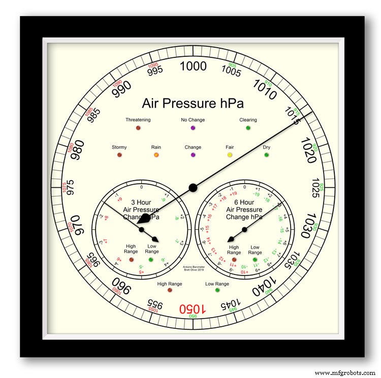
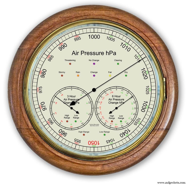
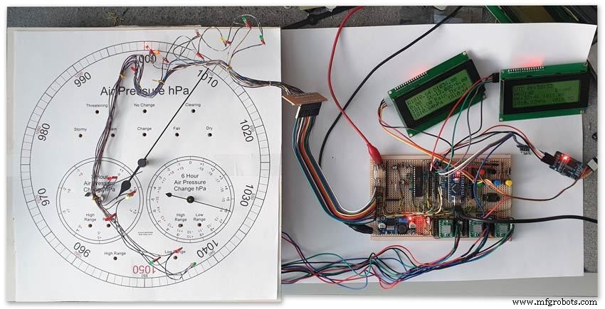
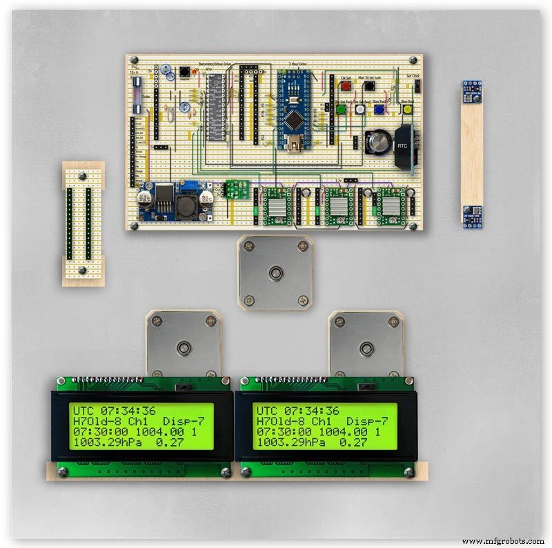
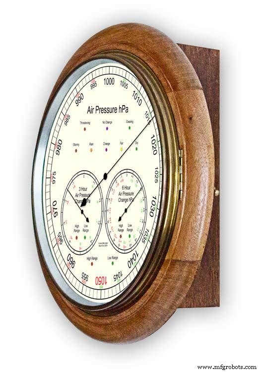
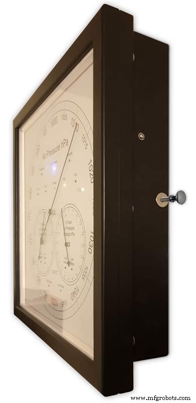
Menggunakan Arduino UNO dan Nano untuk menampilkan Tekanan Udara pada layar analog 12" (300m) menggunakan 3 motor stepper.
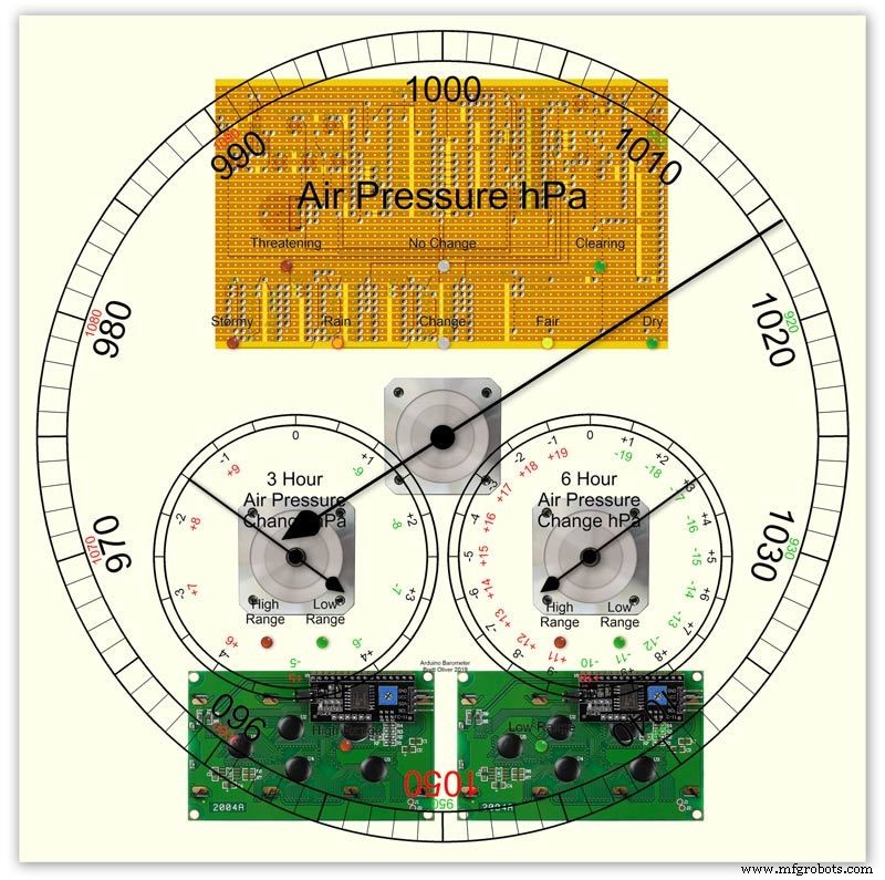
Tersedia 2 pilihan desain dial modern dan klasik.
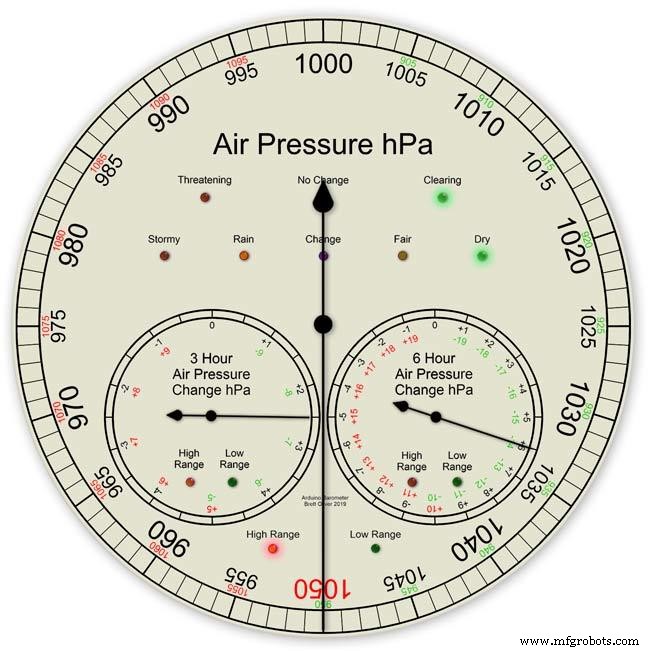
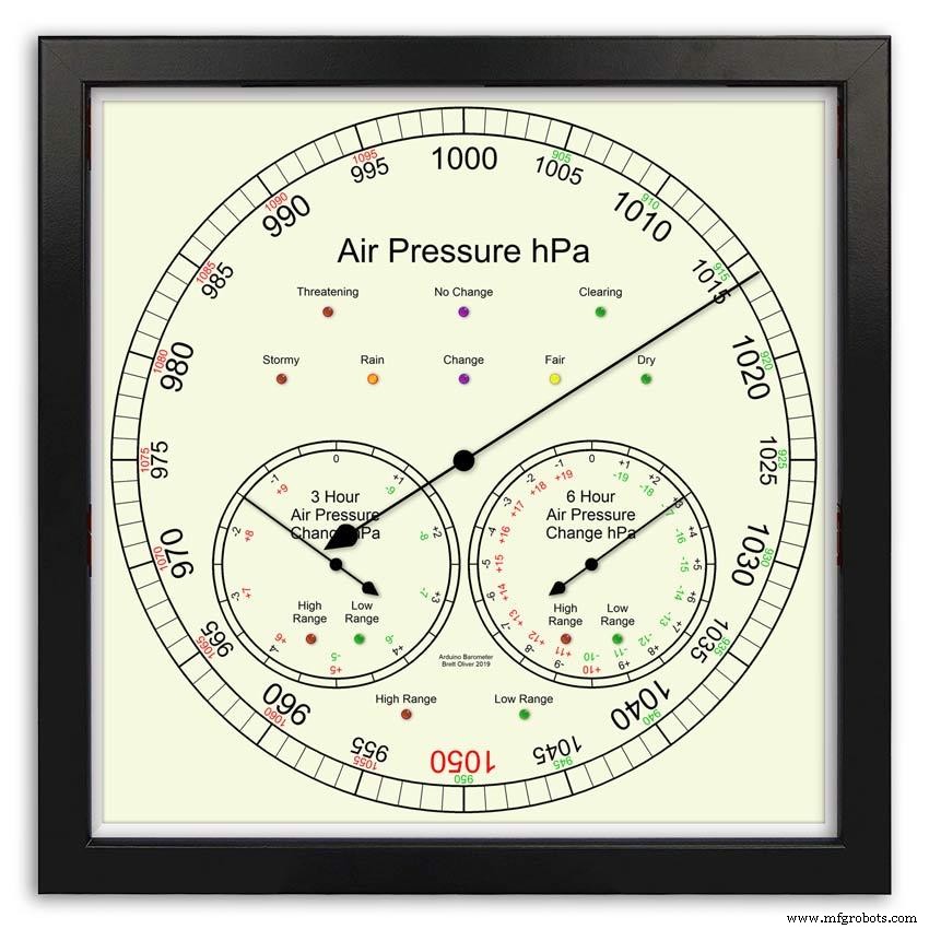
Tekanan Udara dalam hPa (Hectopascal) ditampilkan pada tombol utama besar dan diperbarui setiap 10 menit.
Ada 2 tombol sekunder, satu menunjukkan perubahan tekanan 6 jam terakhir dan yang lainnya menunjukkan perubahan tekanan 3 jam terakhir.
Dial 3 jam memiliki peningkatan resolusi 0,5 hPa karena digunakan untuk prakiraan cuaca. Ada LED untuk menunjukkan saat jangkauan yang diperluas sedang digunakan di ketiga layar dan juga LED untuk menunjukkan prakiraan cuaca dari layar 3 jam.
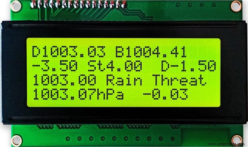
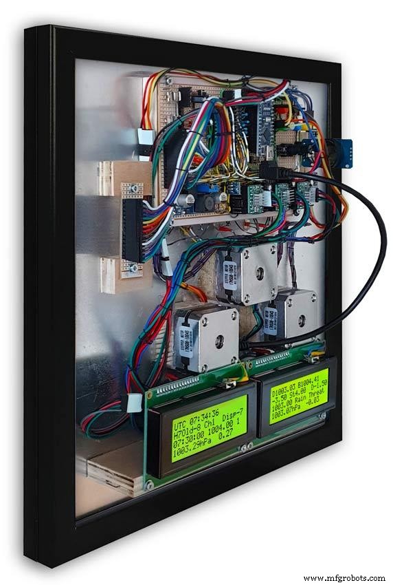
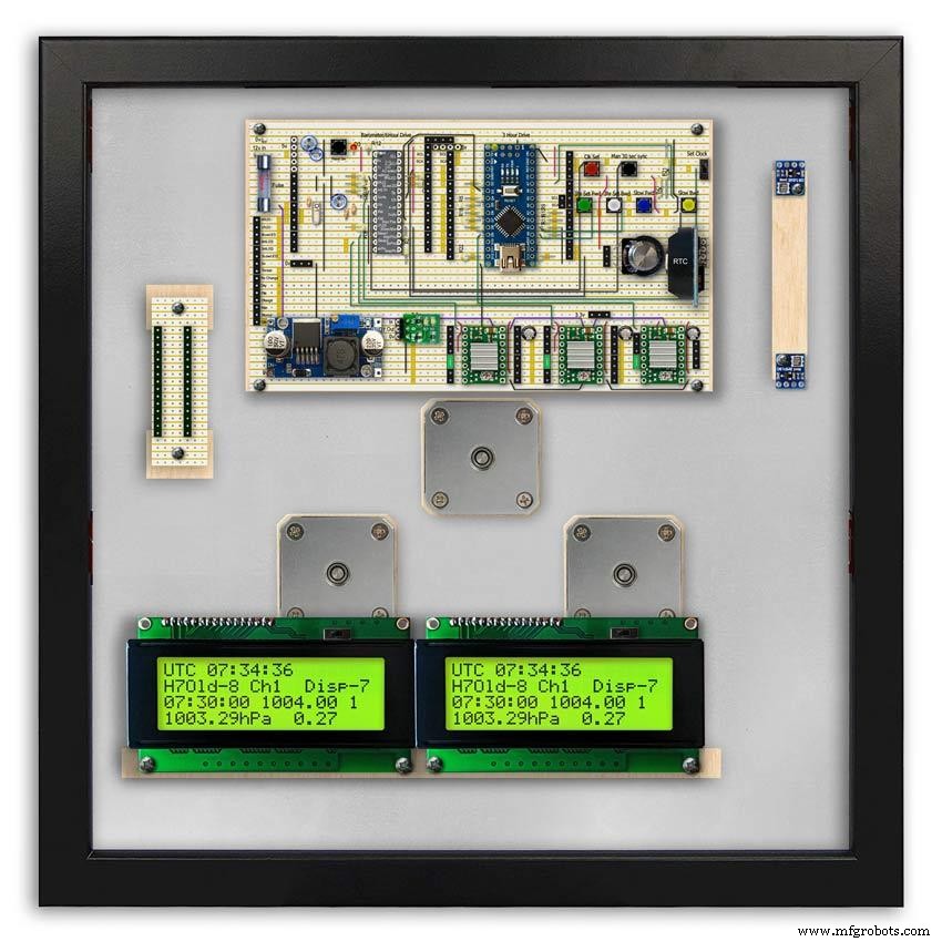
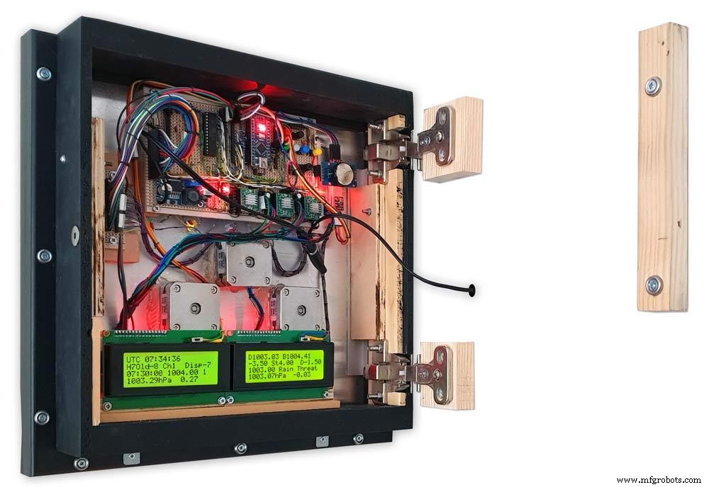
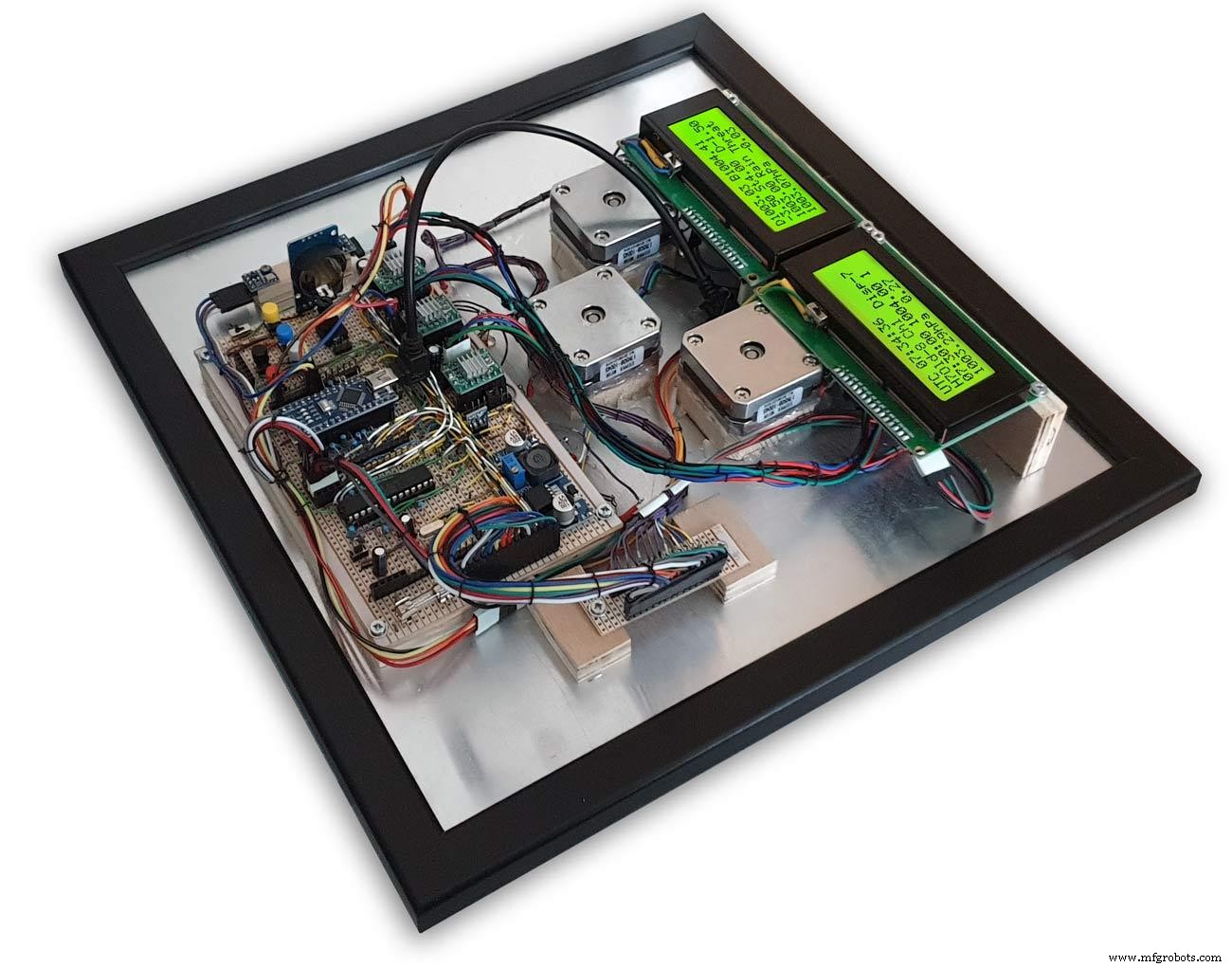
Di dalam casing, dua layar LCD 20x4 menampilkan info dari masing-masing mikroprosesor.
Tampilan tekanan udara utama dan tampilan 6 jam dikendalikan oleh RTC. Jam ini juga menyediakan pulsa 1 jam untuk tampilan 3 jam.
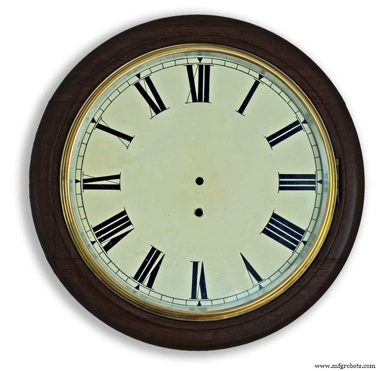
Langkah 1:Perbandingan dengan Barometer Analog Konvensional

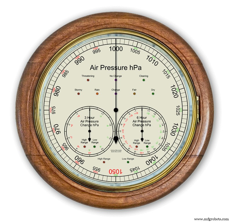
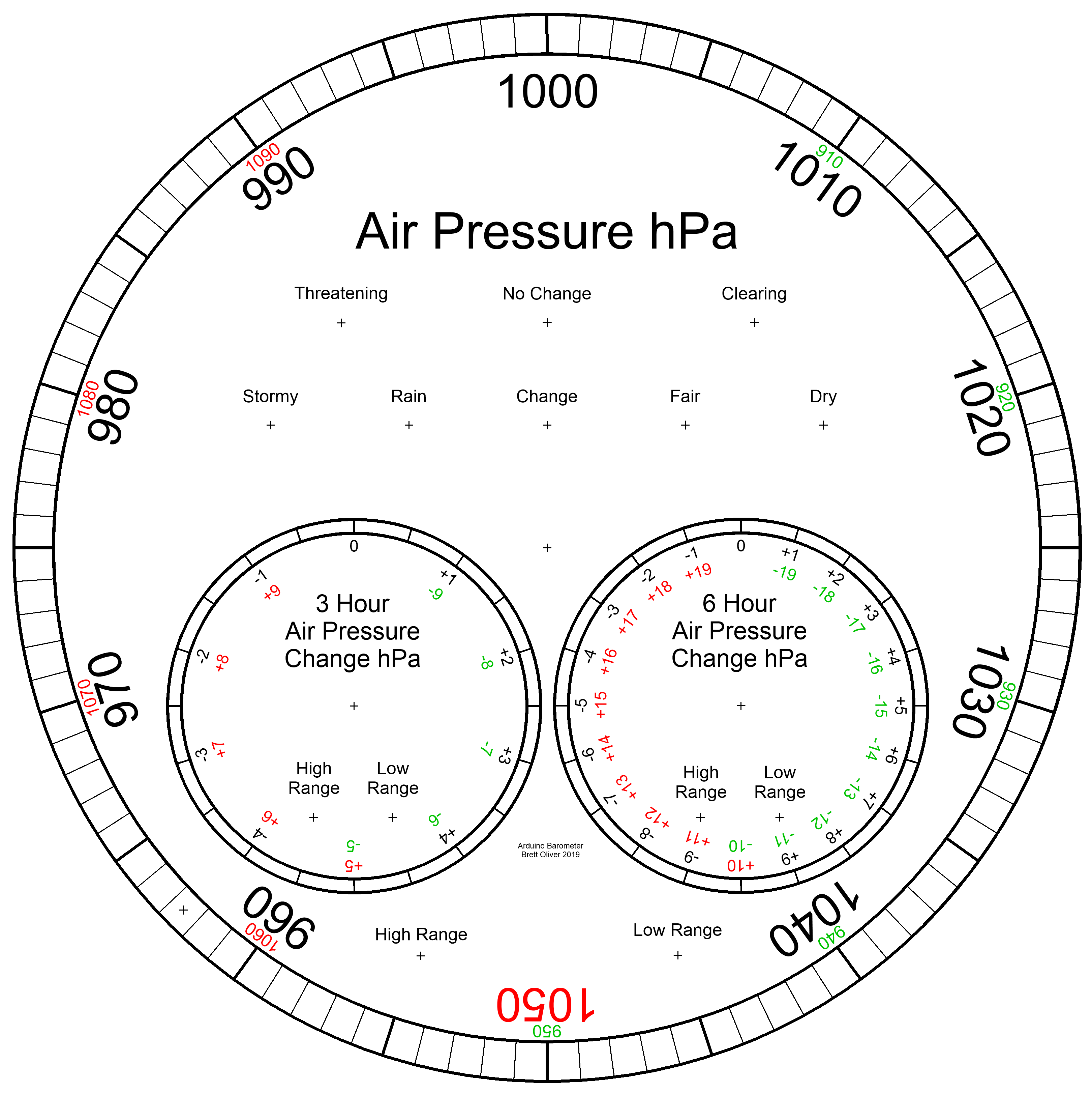
Kebanyakan barometer analog pic. 2 cukup gunakan tekanan udara sebagai indikasi untuk memprediksi cuaca dan Anda harus ingat untuk mengatur penunjuk bergerak dan mencatat waktu yang disetel untuk melihat perubahan tekanan udara.
Cuaca hanya ditulis di sekitar dial dan dibaca dari penunjuk. Peramalan sedikit lebih rumit karena Anda harus menggunakan penunjuk ke-2 dan mencatat perubahan apa pun selama periode 3 jam. Anda harus mengingat kombinasi tekanan saat ini dan tekanan naik/turun untuk mendapatkan perkiraan Anda.
My Barometer terus memantau perubahan tekanan selama periode 3 jam dan 6 jam dan menampilkan pembacaan ini pada 2 tombol yang terpisah.
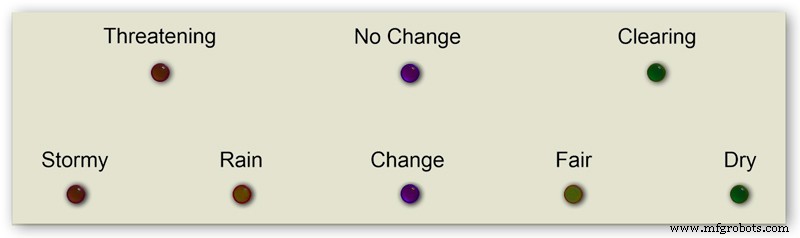
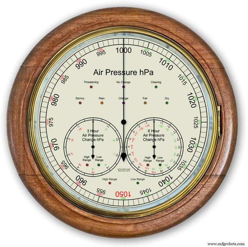
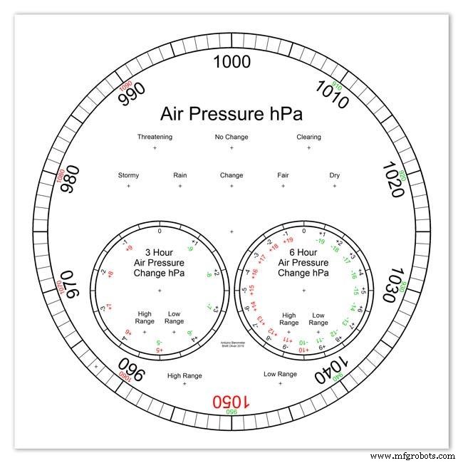
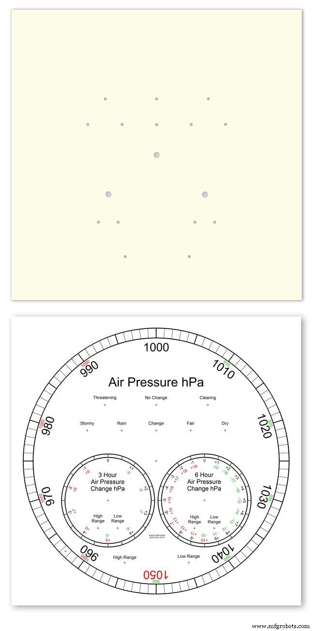
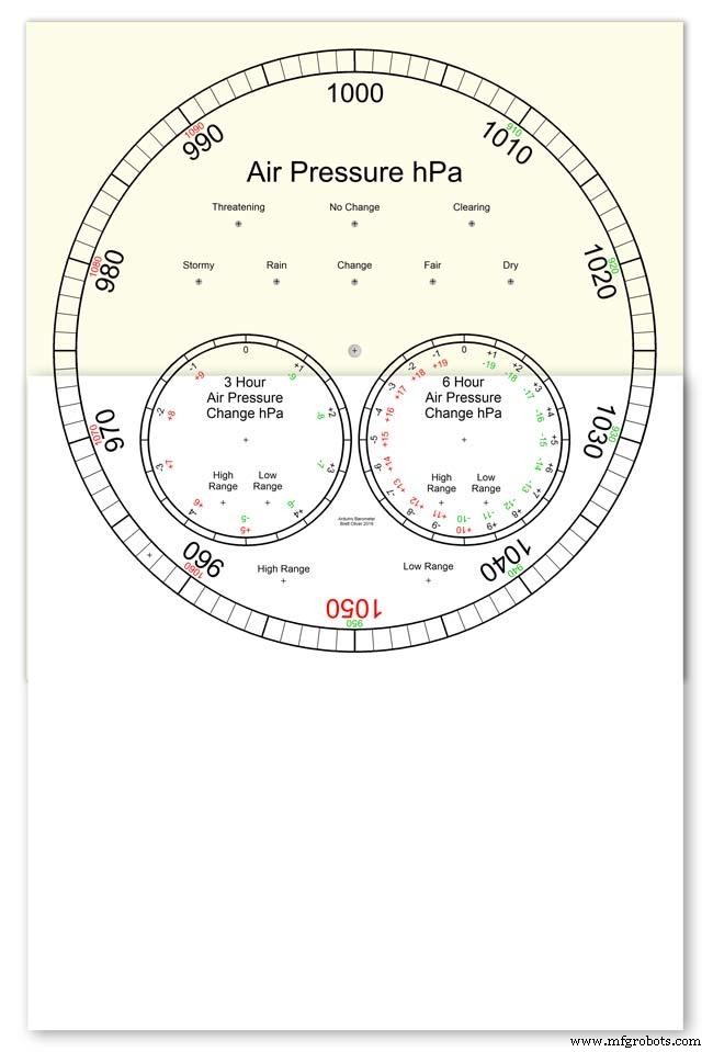
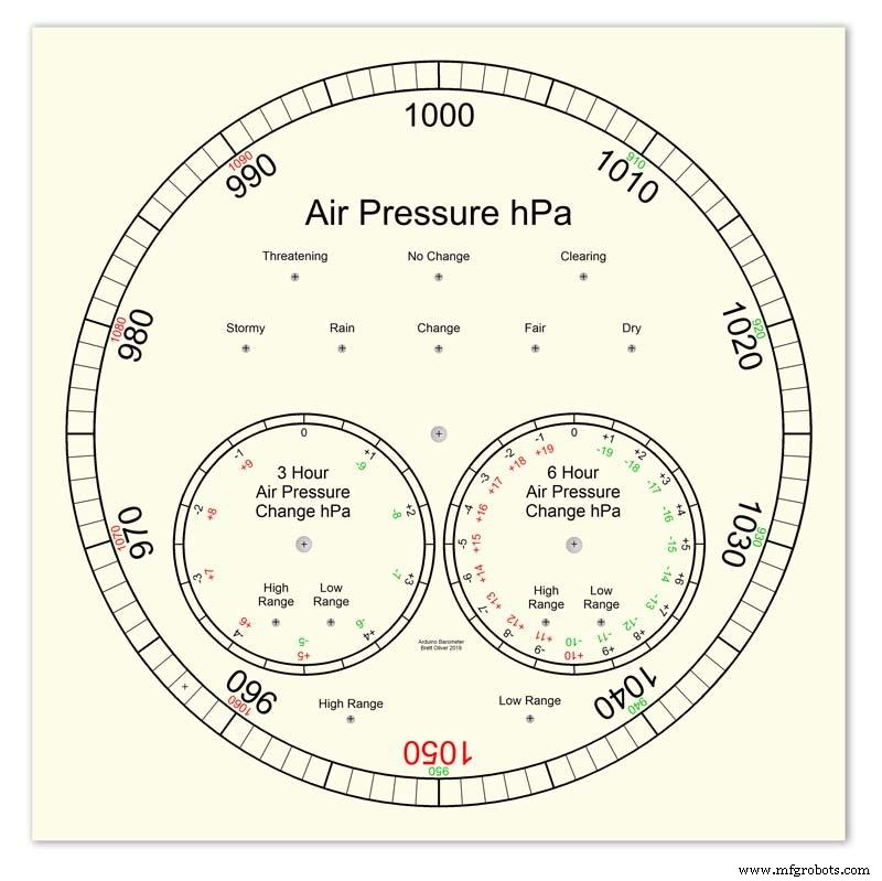
pic.1 menunjukkan kisaran prediksi cuaca barometer saya.
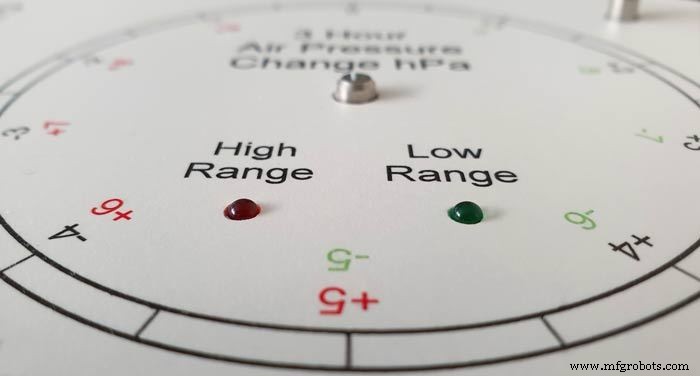
pic.3 menunjukkan close up dari LED prediksi cuaca. Prediksi cuaca didasarkan pada perubahan tekanan udara 3 jam terakhir.
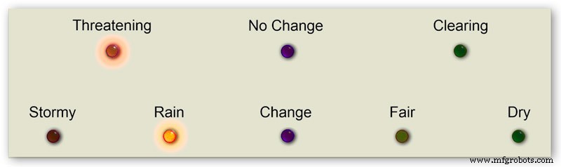
Langkah 2:Demo Barometer Memprediksi Badai

Animasi selang waktu ini menunjukkan bagaimana jarum Barometer dan LED prakiraan bereaksi terhadap badai yang akan datang.
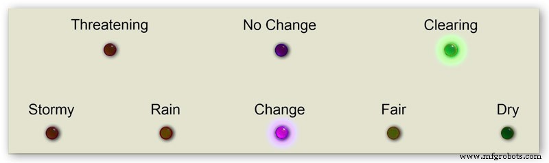
Langkah 3:Panggil Jangkauan Diperpanjang
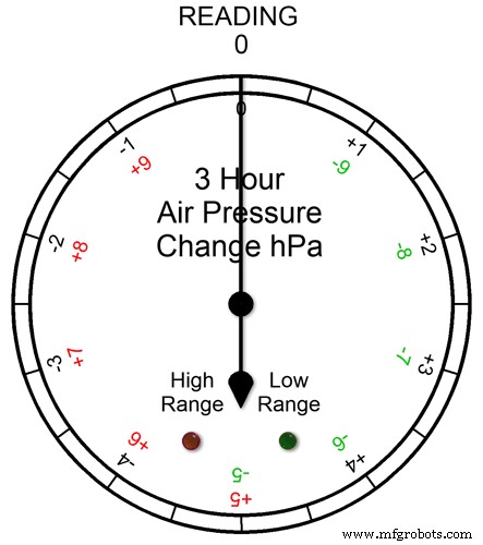

Ketiga dial memiliki rentang yang diperpanjang. Ini memungkinkan resolusi tampilan yang lebih besar pada dial untuk cuaca normal. Dalam kondisi cuaca ekstrim, dial beralih ke jangkauan yang lebih jauh.
Gambar animasi1. menunjukkan bagaimana LED menyala ketika jangkauan yang diperluas sedang beroperasi. LED Merah menunjukkan saat pembacaan +5 ke atas. Anda kemudian akan membaca huruf skala Merah. LED Hijau menunjukkan saat pembacaan adalah -5 dan di bawahnya. Anda kemudian akan membaca huruf skala Hijau. Jika pembacaan melampaui rentang yang diperluas, misalnya pada tombol ini di atas +9 atau -9, kedua LED akan menyala untuk menunjukkan ini- lihat bagian selanjutnya.
Pembacaan tekanan Pada Rentang yang Diperpanjang Pic.2 Jika pembacaan tekanan melebihi rentang + atau - maka kedua LED akan menyala untuk memperingatkan Anda bahwa pembacaan atau perubahan ekstrim telah terjadi. Dial akan tetap menunjukkan pembacaan misalnya pada dial 3 jam jika pembacaannya adalah -10 maka dial akan menunjuk ke 0 dengan kedua LED menyala. Jika pembacaan 3 jam adalah -11 maka dial akan menunjuk ke -1 dengan kedua LED menyala. Anda cukup menambahkan 10 ke bacaan.
Dalam animasi di bawah perbedaan tekanan 3 jam dimulai pada 0 dan perbedaan tekanan turun. Pada -5 hPa lampu LED hijau untuk menunjukkan rentang negatif yang diperpanjang sedang digunakan. Perubahan tekanan terus menurun hingga mencapai -10hPa. Ini sekarang melebihi rentang yang diperluas sehingga LED Merah juga menyala. Tekanan kemudian turun lagi ke -11hPa dan kedua LED tetap menyala. Perubahan tekanan mulai menurun ke -10 hPa dan sekali lagi ini masih dalam rentang yang diperpanjang sehingga kedua LED tetap menyala. Setelah perubahan tekanan turun hingga di bawah -10, LED Merah akan padam menunjukkan rentang yang lebih panjang sedang digunakan kembali.
Saya menyetel rentang yang diperluas ke dial setelah memeriksa cuaca ekstrem di Inggris dan meskipun saya mengharapkan rentang tambahan 3 jam dan 6 jam untuk digunakan, saya tidak berpikir bahwa rentang yang diperluas akan pernah digunakan pada tampilan Barometer utama.
Pic.3 Saat membuat prototipe barometer pada Jan 2020, ada rekor pembacaan tertinggi 1050hPa di Inggris Selatan, barometer utama saya masuk ke rentang tambahan dengan penunjuk pada 1050 merah dan LED rentang tinggi merah menyala.
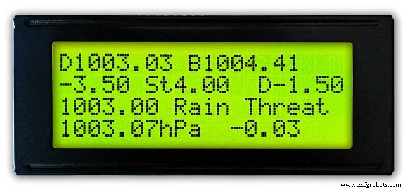
Langkah 4:Tampilan Informasi LCD
3 Jam
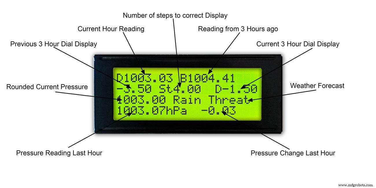
Pic.1 &2 Tampilan ini menunjukkan pembacaan 3 jam dan informasi pada dial 3 jam. Ini juga menunjukkan ramalan cuaca berdasarkan pembacaan saat ini dan 3 jam terakhir.
6 Jam
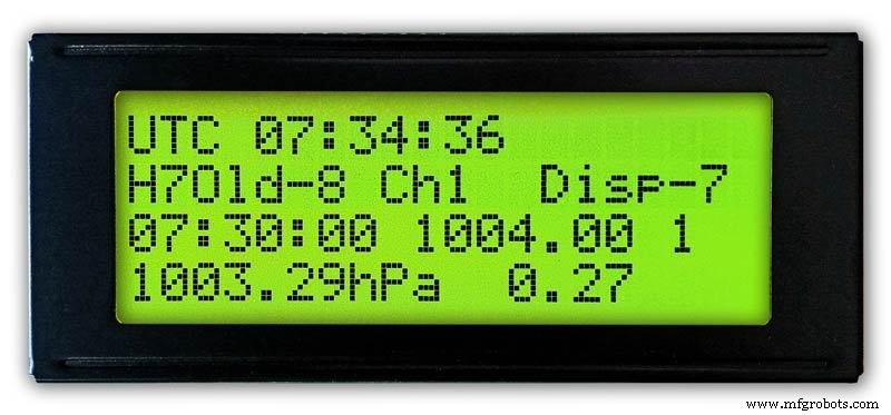
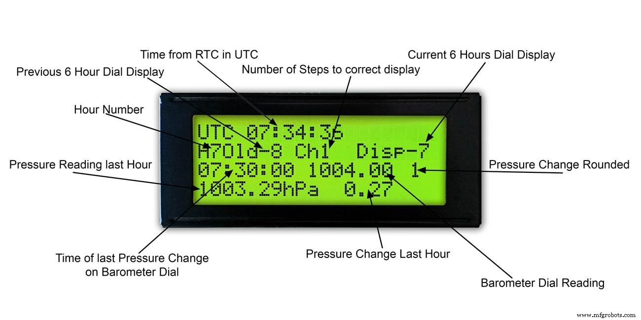
foto 3 &4 Tampilan ini menunjukkan pembacaan tombol barometer utama dan juga pembacaan 6 jam.
Langkah 5:Memprediksi Cuaca

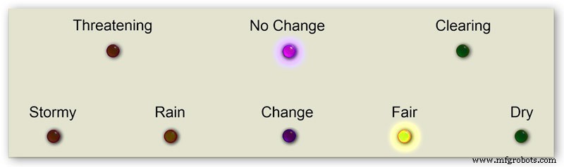


Prakiraan cuaca di barometer saya menggunakan 8 LED.
Menggunakan tekanan udara saat ini dan laju perubahan selama 3 jam terakhir, cuaca diprediksi pada LED.
Animasi 1 menunjukkan berbagai kombinasi kombinasi LED prakiraan.
Saya telah mengunjungi sejumlah situs cuaca dan telah mengumpulkan info berikut tentang memprediksi cuaca dengan barometer.
Memprediksi Cuaca Dengan Barometer
Lebih khusus lagi, barometer dengan pembacaan dalam hPa dapat diinterpretasikan dengan cara ini:
Jika pembacaan lebih dari 1022 hPa
Tekanan yang naik atau stabil berarti cuaca cerah yang berkelanjutan.Tekanan yang turun perlahan berarti cuaca cerah.Tekanan yang turun dengan cepat berarti kondisi berawan dan lebih hangat.
Jika jatuh di antara 1009–1022 hPa
Tekanan yang naik atau stabil berarti kondisi saat ini akan terus berlanjut.Tekanan yang turun perlahan berarti sedikit perubahan cuaca.Tekanan yang turun dengan cepat berarti kemungkinan hujan, atau salju jika cukup dingin.
Jika pembacaan di bawah 1009 hPa
Tekanan yang naik atau stabil menunjukkan cuaca cerah dan lebih dingin.Tekanan yang turun perlahan menunjukkan hujanTekanan yang turun dengan cepat menunjukkan badai akan datang.
Menggunakan info di atas barometer saya menerapkan logika berikut untuk memprediksi cuaca.
Logika diterapkan dalam urutan di bawah ini dengan LED yang dihasilkan menyala.
Pic.2 Tekanan udara <1009 hPa
Tekanan yang meningkat atau stabil menunjukkan cuaca cerah dan lebih dingin
Tekanan Udara <1009.00 dan perubahan 3 jam>=0
Pic.3 Tekanan Udara <1009 hPa
Tekanan yang turun perlahan menandakan hujan
Tekanan Udara <1009.00 dan 3 jam perubahan <0 dan 3 jam perubahan>=-1.5
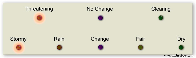
Pic.4 Tekanan Udara <1009 hPa
Tekanan yang turun dengan cepat menunjukkan badai akan datang.
Tekanan Udara <1009.00 dan 3 jam perubahan <-1.5
Gambar 5 Tekanan Udara antara 1009 dan 1022 hPa
Tekanan yang meningkat atau stabil berarti kondisi saat ini akan terus berlanjut.
Tekanan yang turun secara perlahan berarti sedikit perubahan cuaca.
Tekanan Udara>=1009.00 dan Tekanan Udara <=1022.00 dan perubahan 3 jam>=-1.5 dan perubahan 3 jam <=1.5
Pic.6 Tekanan Udara antara 1009 dan 1022 hPa
Tekanan Udara naik dengan cepat berarti cuaca cerah
Tekanan Udara>=1009.00 dan Tekanan Udara <=1022.00 dan perubahan 3 jam> 1,5
Pic.7 Tekanan Udara antara 1009 dan 1022 hPa
Tekanan yang turun dengan cepat berarti kemungkinan hujan, atau salju jika cukup dingin.
Tekanan Udara>=1009.00 dan Tekanan Udara <=1022.00 dan perubahan 3 jam <-1.5
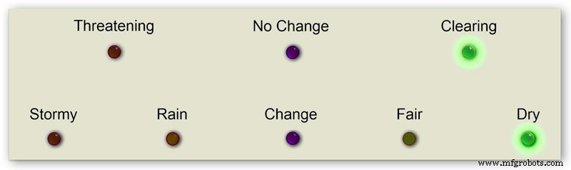
Pic.8 Tekanan Udara di atas 1022 hPa
Naik atau naik tekanan berarti cuaca kering.
Tekanan Udara> 1022.00 dan perubahan 3 jam>=0
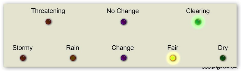
Pic.9 Tekanan Udara di atas 1022 hPa
Tekanan yang turun perlahan berarti cuaca cerah.
Tekanan Udara> 1022.00 dan 3 jam perubahan <0 dan 3 jam perubahan>=-1.5
Pic.10 Tekanan Udara di atas 1022 hPa
Tekanan yang turun dengan cepat berarti perubahan
Tekanan Udara> 1022.00 &&3 jam perubahan <-1.5
Langkah 6:Memulai Barometer
Pada penyalaan awal, tes LED dilakukan.
Setelah selesai jarum akan melangkah ke pengaturan awal mereka siap untuk dikalibrasi.
Langkah 7:RTC Pengaturan Start-up Awal
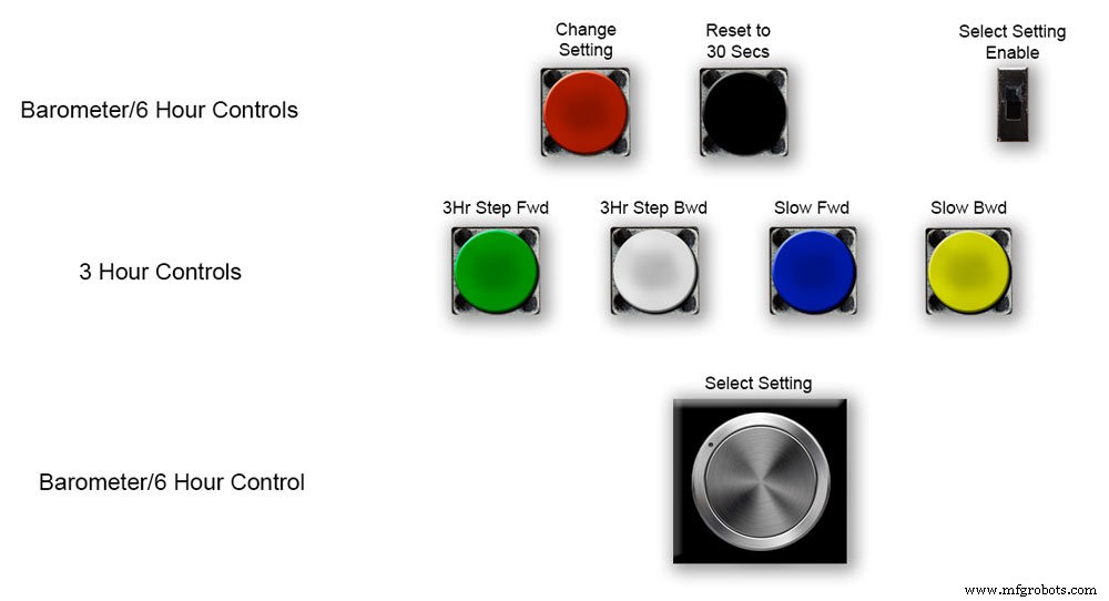


Pic.1 Pada pengaktifan awal, barometer perlu diatur menggunakan kontrol pada Papan Vero.
RTC
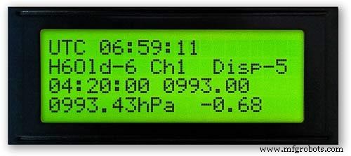
Pic.2 RTC perlu disetel ke waktu yang tepat. Saya menyetelnya ke UTC dan tidak perlu repot mengubah ke waktu musim panas. Sebelum mengatur waktu, perhatikan nilai "Disp" dalam hal ini -5. Ini adalah nilai dari jarum jam 6 dan akan dibutuhkan nanti dalam pengaturan. Geser sakelar "Pilih Pengaturan Aktifkan" ke posisi Nyala. Tampilan tidak akan berubah.
Pic.3 Perlahan putar Knob "Select Setting" searah jarum jam dan baris ke-2 dari layar LCD utama akan berubah.
Berhenti ketika tampilan menunjukkan "RTC Hour Retard" Jika Anda ingin memperlambat RTC hours tekan tombol merah "change setting". Satu klik akan mundur beberapa jam. Beberapa klik akan mengurangi jumlah klik yang ditekan tetapi akan membutuhkan waktu beberapa detik untuk memperbarui RTC.
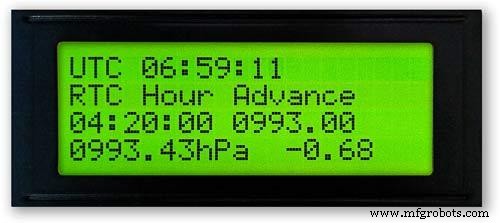
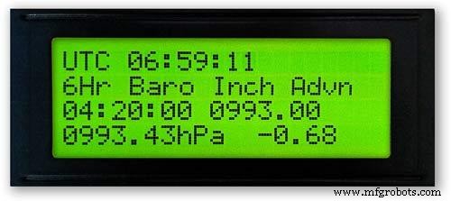
Pic.4 Memutar Knob "Select Setting" lebih jauh akan mengubah tampilan menjadi "RTC Hour Advance"
Jika Anda ingin memajukan jam RTC, tekan tombol merah "ubah pengaturan". Satu klik akan mempercepat waktu. Beberapa klik akan meningkatkan jumlah klik yang ditekan tetapi akan membutuhkan waktu beberapa detik untuk memperbarui RTC.
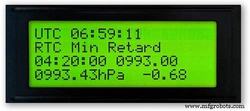
Pic.5 Memutar Knob "Select Setting" lebih lanjut akan mengubah tampilan menjadi "RTC Min Retard"
Jika Anda ingin memperlambat menit RTC, tekan tombol merah "ubah pengaturan". Satu klik akan membuat mundur beberapa menit. Beberapa klik akan mengurangi jumlah klik yang ditekan tetapi akan membutuhkan waktu beberapa detik untuk memperbarui RTC.
Pic.6 Memutar Knob "Select Setting" lebih lanjut akan mengubah tampilan menjadi "RTC Min Advance"
Jika Anda ingin memajukan menit RTC, tekan tombol merah "ubah pengaturan". Satu klik akan mempercepat menit. Beberapa klik akan meningkatkan jumlah klik yang ditekan tetapi akan membutuhkan waktu beberapa detik untuk memperbarui RTC.
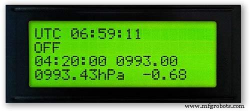
Pic.7 Setelah Anda menyelesaikan pengaturan RTC atau pengaturan lainnya, kembalikan Knob "Select Setting" sepenuhnya berlawanan arah jarum jam hingga tampilan menunjukkan "Off"
Geser tombol "Select Setting Enable" ke posisi Off.
Catatan. Detik dapat disinkronkan menjadi 30 detik kapan saja dengan menekan tombol hitam "Reset ke 30 detik". Waktu sekarang akan diingat di RTC jika daya dimatikan.
Langkah 8:Pengaturan Start-up Awal Jarum 6 Jam


Menyetel jarum jam 6
Pic.1 Setelah RTC disetel, barometer dan jarum penunjuk tekanan udara 6 jam perlu disetel.
Geser sakelar "Pilih Pengaturan Aktifkan" ke posisi Nyala. Tampilan tidak akan berubah.
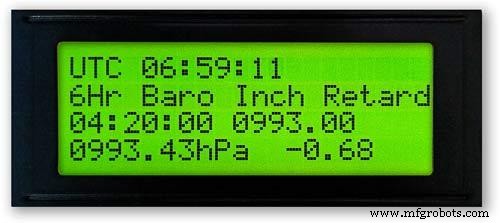
Putar perlahan Knob "Select Setting" searah jarum jam hingga "6Hr Baro Inch Retard" ditampilkan.
Saat pertama kali dinyalakan, jarum jam 6 jam perlu dikalibrasi ke angka terdekat.
Jika angka terdekat berada di belakang tangan, tekan tombol merah "ubah pengaturan". Satu klik akan membuat tangan mundur selangkah demi selangkah. Menahan tombol akan membuat tangan mundur berulang kali. Setelah jarum tepat berada di angka, lepaskan tombolnya.
Pic.2 Jika angka terdekat di depan tangan atau jika Anda memiliki inci yang lebih lambat dari tangan menggunakan angka di atas terlalu banyak, putar Knob "Select Setting" searah jarum jam hingga "6Hr Baro Inch Advn" ditampilkan.
Tekan tombol merah "ubah pengaturan". Satu klik akan menggerakkan tangan ke depan selangkah demi selangkah. Menahan tombol akan menggerakkan tangan ke depan berulang kali. Setelah jarum tepat berada di angka, lepaskan tombolnya.
Pic.3 Setelah jarum jam 6 disetel tepat pada angka, jarum jam harus disetel ke nilai yang benar.
Sebelum menyesuaikan RTC, Anda mencatat nomor -5 ini.
Pic.4 Jika jarum penunjuk jam 6 terlalu maju.
Putar Knob "Select Setting" searah jarum jam hingga "6Hr Baro Retard" ditampilkan. Tekan dan lepaskan tombol merah "ubah pengaturan". Ambang ini melangkah jarum jam 6 mundur 1 unit utuh. Berhentilah ketika jarum jam 6 mencapai angka yang Anda catat.
Pic.5 Jika jarum penunjuk jam 6 dimundurkan.
Putar Knob "Select Setting" searah jarum jam hingga "6Hr Baro Advance" ditampilkan. Tekan dan lepaskan tombol merah "ubah pengaturan". Ambang ini melangkah jarum jam 6 ke depan 1 unit utuh. Berhentilah ketika jarum jam 6 mencapai angka yang Anda catat.
Pic.6 Perhatikan bahwa tampilan 6 jam akan memakan waktu 8 jam untuk ditampilkan dengan benar karena perlu menyimpan bacaan dalam memori selama periode waktu tersebut.
Anda selalu dapat menambahkan pembacaan tekanan udara sebelumnya ke dalam kode sebelum memuat jika Anda memerlukan tampilan 6 jam untuk berfungsi dari startup.
Kode mengubah jam menjadi angka H seperti yang ditampilkan di atas H =6.Pada baris kode 128 H6 berarti menempatkan pembacaan jam saat ini di bawah jam6 pembacaan sebelumnya pada jam7 pembacaan sebelumnya pada jam0 dll
int jam0 =1015;
int jam1 =1016
;int jam2 =1015;
int jam3 =1016;
int jam4 =1016
;int jam5 =1016;
int jam6 =1012;
int jam7 =1013;
Anda seharusnya bisa mendapatkan bacaan lokal Anda dari internet.
Saya menyiapkan halaman dari stasiun cuaca saya sehingga saya dapat memeriksanya saat membuat barometer.
Klik tautan ini untuk melihat perubahan per jam di Kenley Surrey UK.
Langkah 9:Pengaturan Start-up Awal Jarum Barometer Utama


Menyetel jarum barometer utama
Pic.1 Sekarang tampilan 6 jam sudah benar, jarum barometer utama perlu disetel ke tekanan permukaan laut yang dibulatkan pada baris ke-3 di bawah pada LCD utama.
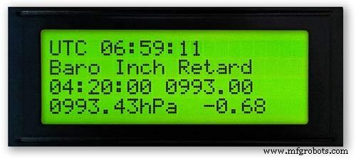
Pada power up pertama tangan barometer utama perlu kalibrasi ke digit terdekat. Putar Knob "Select Setting" searah jarum jam hingga "Baro Inch Retard" ditampilkan.
Jika angka terdekat berada di belakang tangan, tekan tombol merah "ubah pengaturan". Satu klik akan membuat tangan mundur selangkah demi selangkah. Menahan tombol akan membuat tangan mundur berulang kali. Setelah jarum tepat berada di angka, lepaskan tombolnya.
Pic.2 Jika angka terdekat di depan tangan atau jika Anda memiliki inci yang lebih lambat dari tangan menggunakan angka di atas terlalu banyak, putar Knob "Select Setting" searah jarum jam hingga "Baro Inch Advn" ditampilkan.
Tekan tombol merah "ubah pengaturan".
Satu klik akan menggerakkan tangan ke depan selangkah demi selangkah. Menahan tombol akan menggerakkan tangan ke depan berulang kali. Setelah tangan tepat berada pada angka, lepaskan tombol.
Pic.3 Jika jarum barometer utama terlalu maju.
Putar Knob "Select Setting" searah jarum jam hingga "Barometer Retard" ditampilkan.
Tekan dan lepaskan tombol merah "ubah pengaturan".
Ini akan menggerakkan tangan barometer utama mundur 1 unit utuh. Berhenti ketika jarum jam mencapai tekanan permukaan laut bulat yang ditunjukkan.
Pic.4 Jika jarum barometer utama diperlambat dibandingkan dengan tekanan permukaan laut bulat yang ditunjukkan.
Putar Knob "Select Setting" searah jarum jam hingga "Barometer Advance" ditampilkan.
Tekan dan lepaskan tombol merah "ubah pengaturan".
Ini akan menggerakkan tangan barometer utama ke depan 1 unit utuh. Berhenti ketika jarum mencapai tekanan permukaan laut bulat yang ditunjukkan.
Langkah 10:Pengaturan Start-up Awal Jarum 3 Jam


Menyetel jarum 3 jam.
Oic.1 Penyesuaian jarum jam 3 dilakukan dengan empat tombol Hijau, Putih, Biru dan Kuning pada papan Vero.
Saat dinyalakan awal, jarum jam 3 jam perlu dikalibrasi ke unit terdekat atau setengah unit.
Pic.2 Jika jarum 3 jam terdekat nilai unit di depan jarum 3 jam tekan tombol Kuning "Slow Bwd" untuk inci jarum mundur. Menekan tombol akan berulang kali menggerakkan tangan ke belakang.
Jika jarum 3 jam nilai unit terdekat berada di belakang jarum 3 jam, tekan tombol Biru "Fwd Lambat" untuk menggerakkan jarum ke depan. Menekan tombol akan berulang kali menggerakkan tangan ke depan.
Setelah jarum jam 3 tepat berada pada satu unit/setengah unit, jarum jam dapat disetel ke nilai "D" pada layar LCD 3 jam.
Jika jarum di depan nilai "D" tekan tombol Putih "3Hr Step Bwd" untuk menggerakkan jarum jam 3 jam dalam setengah unit ke belakang.
Jika jarum di jarum kurang dari nilai "D" tekan tombol Hijau "3Hr Step Fwd" untuk menggerakkan jarum jam 3 jam ke depan setengah satuan.
Perhatikan bahwa tampilan 3 jam akan membutuhkan waktu 4 jam untuk ditampilkan dengan benar karena perlu menyimpan bacaan dalam memori selama periode waktu tersebut.
Anda selalu dapat menambahkan pembacaan tekanan udara sebelumnya ke dalam kode sebelum memuat jika Anda memerlukan prakiraan dan tampilan 3 jam untuk berfungsi dari startup.
Kode tampilan 3 jam pada baris 124
float hour0 adalah jam saat ini
float hour1 adalah jam sebelumnya dll dll
float hour0 =1036.00;
float hour1 =1036.00;
float hour2 =1036.00;
float hour3 =1036.00;
float hour4 =1036.00;
Anda seharusnya bisa mendapatkan bacaan lokal Anda dari internet.
Langkah 11:Modul/Komponen

Modul
Jika memungkinkan, proyek ini menggunakan modul bawaan untuk menghemat waktu konstruksi dan desain.
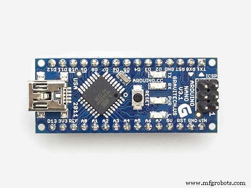
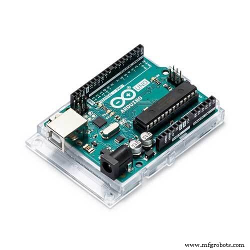
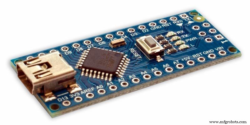
Mikroprosesor
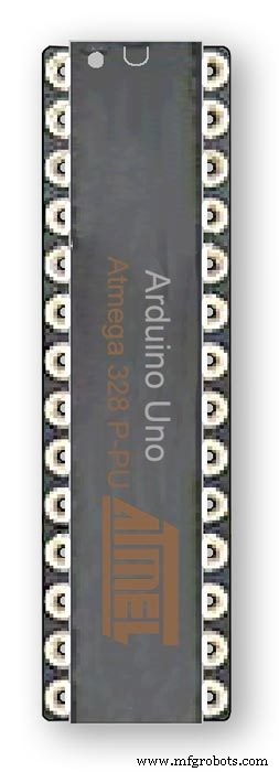
Proyek ini menggunakan 2 mikroprosesor Atmega 328(UNO) pic.1 dan Arduino Nano pic.2. Saya telah menggunakan kombinasi ini karena saya sudah memiliki 328 yang dibangun dari proyek lain dan karena ruang terbatas di Papan Vero, saya juga menambahkan Nano.
Kekuatan
Barometer menggunakan sekitar 65mA dan ini akan meningkat sedikit karena setiap motor melangkah selama sepersekian detik setiap 10 menit ke dan jam
AMS117 gambar.3
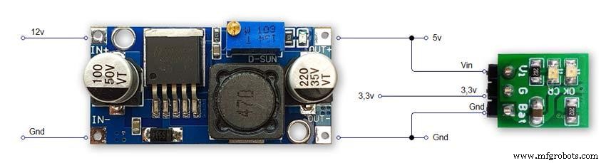
Modul pada proyek ini adalah 3.3v dan digunakan untuk memberi daya pada modul BMP180.
Rangkaian regulator tegangan tetap dan dapat disesuaikan seri AMS1117 dirancang untuk menyediakan arus keluaran hingga 1A dan beroperasi hingga diferensial input-ke-output 1V. Tegangan putus perangkat dijamin maksimum 1.3V, menurun pada arus beban yang lebih rendah. Pemangkasan pada chip menyesuaikan tegangan referensi menjadi 1,5%. Batas arus diatur untuk meminimalkan tegangan dalam kondisi kelebihan beban pada regulator dan sirkuit sumber daya. Modul pada proyek ini adalah 3.3v dan digunakan untuk memberi daya pada modul BMP180.
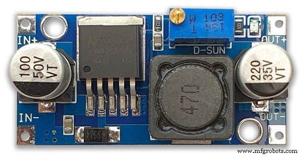
LM2596 Buck DC to DC Converter 3.0-40V ke 1.5-35V pic.4Modul ini mengubah input 12v menjadi 5v
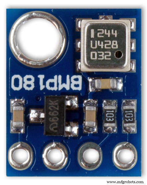
Modul Sensor Tekanan BMP180 2 mati pic.5 Breakout BMP180 adalah sensor tekanan barometrik dengan antarmuka I2C ("Kawat"). Sensor tekanan barometrik mengukur tekanan absolut udara di sekitar mereka. Tekanan ini bervariasi dengan cuaca dan ketinggian. Bergantung pada cara Anda menafsirkan data, Anda dapat memantau perubahan cuaca, mengukur ketinggian, atau tugas lain apa pun yang memerlukan pembacaan tekanan yang akurat.
Hubungkan pin +, -, CL, dan DA ke Arduino Anda.
CL ke SCL dan DA ke SDA.
PENTING:Hubungkan pin daya (+ dan -) HANYA ke catu daya 3.3V. Tegangan yang lebih besar akan merusak komponen secara permanen. Perhatikan bahwa karena I2C menggunakan driver saluran terbuka, maka aman untuk menghubungkan pin I2C (DA dan CL) ke port I2C pada mikroprosesor 5V.
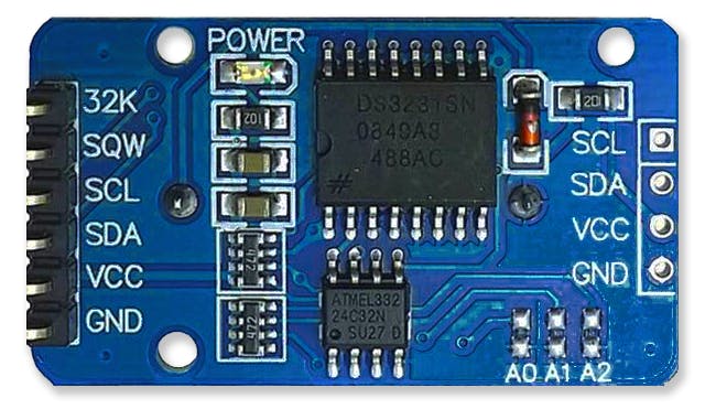
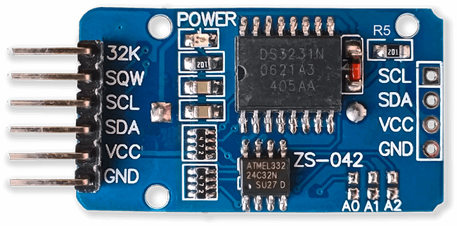
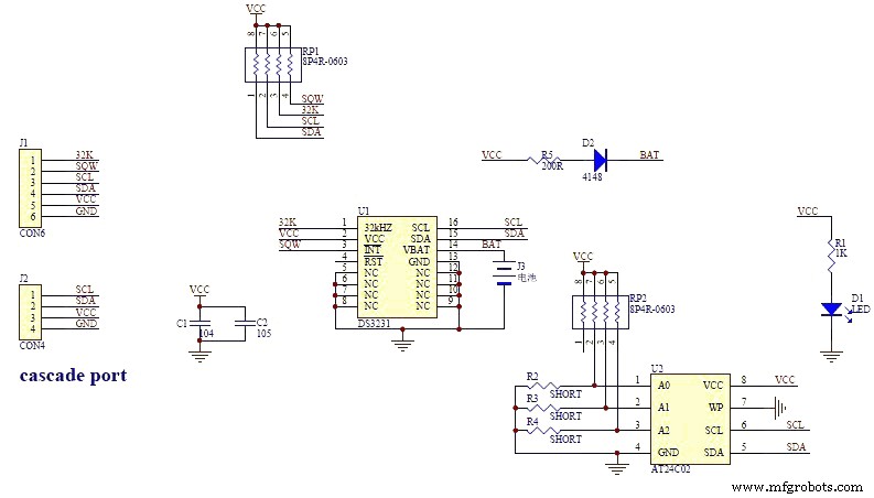
Gambar jam waktu nyata RTC.6
Brometer ini menggunakan Modul Jam Waktu Nyata Presisi DS3231 AT24C32 I2C.
Modul ini digunakan terutama untuk pengaturan waktu tetapi juga menyediakan stempel waktu pada layar LCD. Waktu diatur ke UTC dan tidak diubah untuk musim panas. Modul ini dilengkapi dengan baterai isi ulang Lithium-Ion, lihat diagram di atas. Saya menggunakan baterai yang tidak dapat diisi ulang, jadi saya telah melepas resistor R5 dari modul, lihat bagian Modifikasi RTC untuk detailnya.
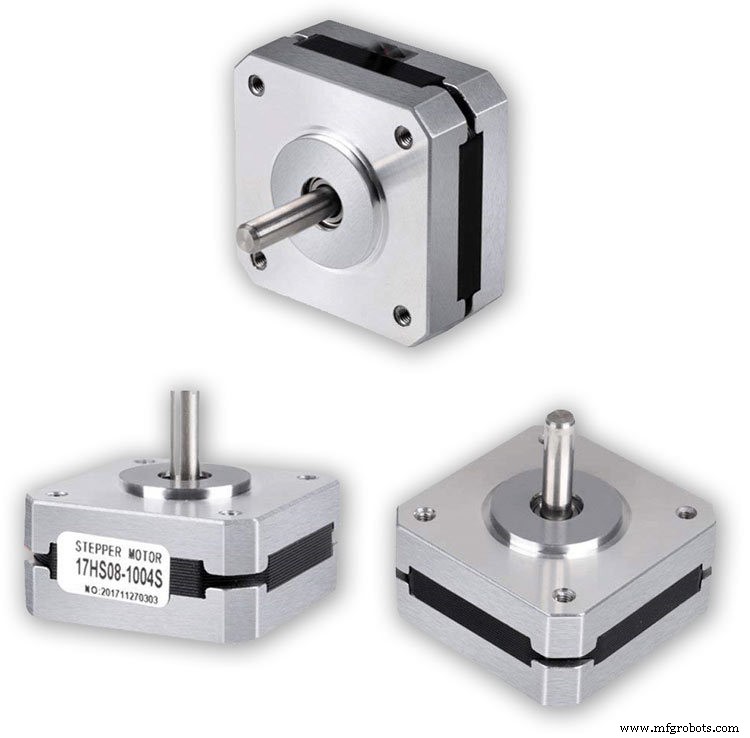
Motor Stepper 3 mati Barometer menggunakan 3 Nema 17 Stepper Motors 1A, Torsi Penahan 13N.cm, 4-Lead, 1,8° Saya menggunakan motor 1,8° karena anak tangganya pas hingga 360° 200 kali. Anda dapat menggunakan motor Nema 8 jika diinginkan tetapi jangan gunakan motor 28BYJ-48-5V karena motor tersebut tidak memiliki sudut langkah 1,8° yang diperlukan.
Sudut langkah 1,8° diperlukan karena membagi tepat 360° untuk tombol barometer saya.
Layar LCD 2 mati
Saya telah menggunakan 2 layar LCD 20x4 satu untuk tampilan Barometer, jam dan 6 jam dan yang lainnya untuk tampilan dan ramalan 3 jam.
Langkah 12:Modul/Komponen Driver Motor Stepper A4988
Driver motor stepper bipolar microstepping A4988 3 mati
Penting untuk membaca bagian ini dengan cermat
Barometer saya disetel ke putaran 1/16 langkah dan kodenya disesuaikan.
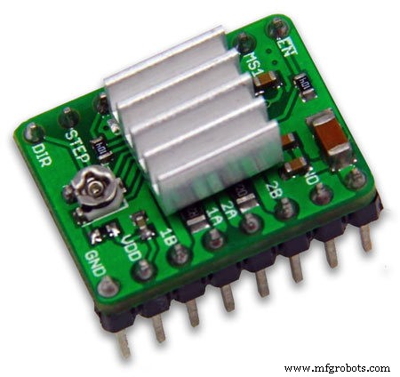
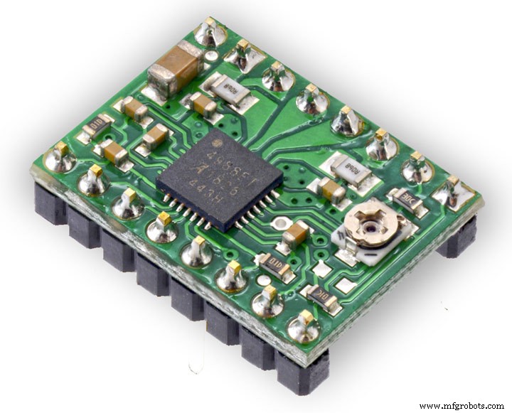
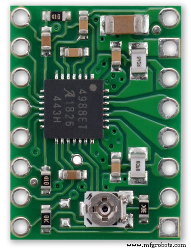
A4988 microstepping bipolar stepper motor driver pic.1 dengan dan pic.2 tanpa heatsink
Papan breakout untuk driver motor stepper bipolar microstepping A4988 Allegro ini memiliki fitur pembatas arus yang dapat disesuaikan, perlindungan arus berlebih dan suhu berlebih, dan lima resolusi microstep yang berbeda (turun ke 1/16-langkah).
Ini beroperasi dari 8 V hingga 35 V dan dapat menghasilkan hingga sekitar 1 A per fase tanpa heat sink atau aliran udara paksa (dinilai untuk 2 A per koil dengan pendinginan tambahan yang memadai).
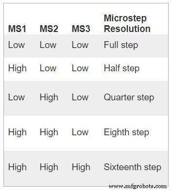
Berikut adalah beberapa fitur utama pengemudi:Antarmuka kontrol langkah dan arah yang sederhana Lima resolusi langkah yang berbeda:langkah penuh, setengah langkah, seperempat langkah, langkah kedelapan, dan langkah keenam belas Kontrol arus yang dapat disesuaikan memungkinkan Anda mengatur output arus maksimum dengan potensiometer, yang memungkinkan Anda menggunakan voltase di atas voltase pengenal motor stepper Anda untuk mencapai laju langkah yang lebih tinggi Kontrol pencacahan cerdas yang secara otomatis memilih mode peluruhan arus yang benar (peluruhan cepat atau peluruhan lambat) Shutdown termal suhu berlebih, penguncian di bawah voltase, dan Proteksi arus silang Proteksi short-to-ground dan short-load
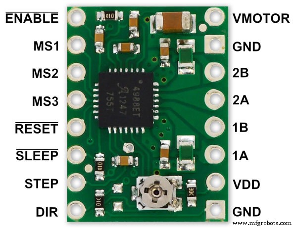
Sambungan daya Driver memerlukan tegangan suplai logika (3 – 5,5 V) untuk dihubungkan melalui pin VDD dan GND dan tegangan suplai motor (8 – 35 V) untuk dihubungkan melalui VMOT dan GND. Pasokan ini harus memiliki kapasitor decoupling yang sesuai di dekat papan, dan harus mampu memberikan arus yang diharapkan (puncak hingga 4 A untuk suplai motor).
Peringatan:Papan pembawa ini menggunakan kapasitor keramik ESR rendah, yang membuatnya rentan terhadap lonjakan tegangan LC yang merusak, terutama saat menggunakan kabel daya yang lebih panjang dari beberapa inci. Dalam kondisi yang tepat, paku ini dapat melebihi peringkat tegangan maksimum 35 V untuk A4988 dan merusak papan secara permanen, bahkan ketika tegangan suplai motor serendah 12 V. Salah satu cara untuk melindungi pengemudi dari paku tersebut adalah untuk menempatkan kapasitor elektrolit besar (setidaknya 47 F) di seluruh daya motor (VMOT) dan ditanahkan di suatu tempat yang dekat dengan papan.
Sambungan motor
Motor stepper empat, enam, dan delapan kawat dapat digerakkan oleh A4988 jika terhubung dengan benar. Warning:Connecting or disconnecting a stepper motor while the driver is powered can destroy the driver. (More generally, rewiring anything while it is powered is asking for trouble.)
Step (and microstep) size
see table pic. 3Stepper motors typically have a step size specification (e.g. 1.8° or 200 steps per revolution), which applies to full steps. A microstepping driver such as the A4988 allows higher resolutions by allowing intermediate step locations, which are achieved by energizing the coils with intermediate current levels. For instance, driving a motor in quarter-step mode will give the 200-step-per-revolution motor 800 microsteps per revolution by using four different current levels.
The resolution (step size) selector inputs (MS1, MS2, and MS3) enable selection from the five step resolutions according to the table below. MS1 and MS3 have internal 100kΩ pull-down resistors and MS2 has an internal 50kΩ pull-down resistor, so leaving these three microstep selection pins disconnected results in full-step mode. For the microstep modes to function correctly, the current limit must be set low enough (see below) so that current limiting gets engaged. Otherwise, the intermediate current levels will not be correctly maintained, and the motor will skip microsteps.
Control inputs
pics 4 &5Each pulse to the STEP input corresponds to one microstep of the stepper motor in the direction selected by the DIR pin. Note that the STEP and DIR pins are not pulled to any particular voltage internally, so you should not leave either of these pins floating in your application.
If you just want rotation in a single direction, you can tie DIR directly to VCC or GND. The chip has three different inputs for controlling its many power states:RST, SLP, and EN. For details about these power states, see the datasheet.
Please note that the RST pin is floating; if you are not using the pin, you can connect it to the adjacent SLP pin on the PCB to bring it high and enable the board.
Current LImiting Before connecting the motor we should adjust the current limiting of the driver so that we are sure that the current is within the current limits of the motor. We can do that by adjusting the reference voltage using the potentiometer on the module to set the VRef.
See details on the video link pic. 6
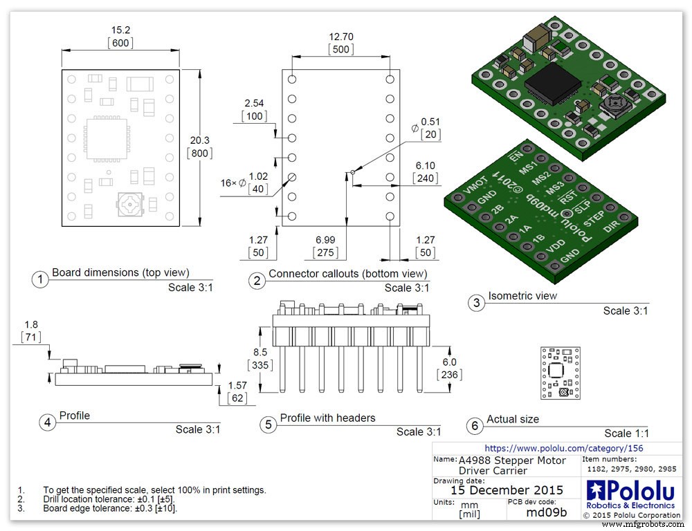
Manufacturers Drawing sheet pic.7
Step 13:Construction Prototyping
The circuit was prototyped using a hardboard dial with holes drilled for the motor spindles and LEDs.
Various dial designs were then printed on normal paper and Sellotaped over the top. The LED wiring loom was made with the LEDs in position on the temporary dial.
If you are using the round dial design this will allow you to check if the board etc will be mounted on the dial or in the back box.
Step 14:Construction RTC Modification
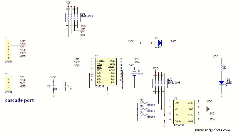
The module comes supplied with a Lithium-Ion rechargeable battery see diagram pic. 2.
I use a non rechargeable battery (I am not happy with the circuit design with a lithium-iron battery and associated fire risk) of the so have removed resistor R5 from the module as below. This stops any charge current to the battery.
Pic.3 shows the module without the resistor (just break it off) and pic.4 the modified circuit.
Step 15:Construction Mounting Modules &Boards
On the modern square dial design all the modules and boards are mounted on the dial. The classic round dial desgn will need some parts mounted in the back box as there is less space on the dial.
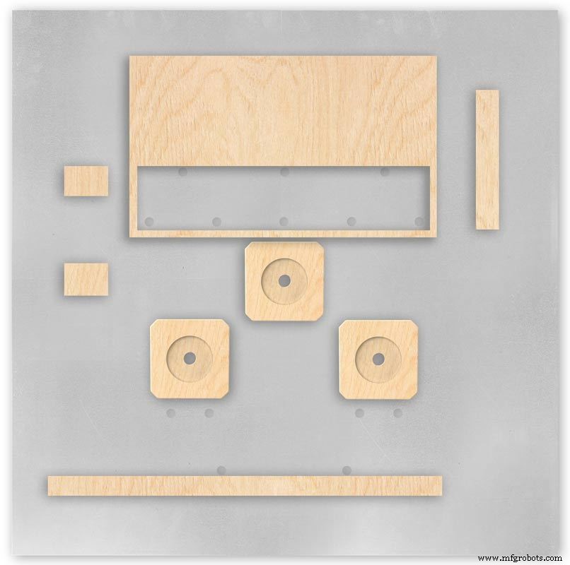
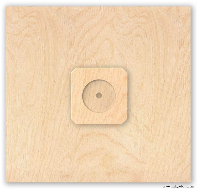
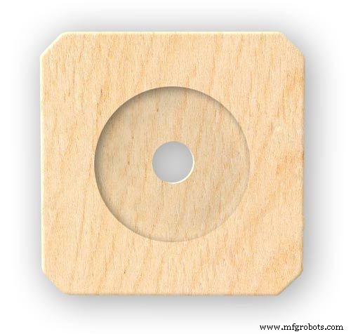
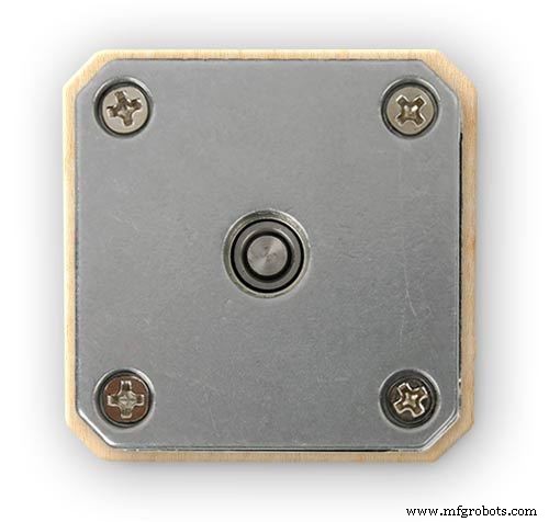
Motors are hot melt glued to wooden mounting blocks pic.1&2. The wooded blocks are cut fron a sheet of plywood pic.3. The mounting blocks depths are set to allow the correct protrusion of the spindles through the dial. I have hot melt glued the blocls to the dial.
The Vero Boards and LCD displays are also screwed to wooden blocks which have been glued to the dial using impact adhesive.
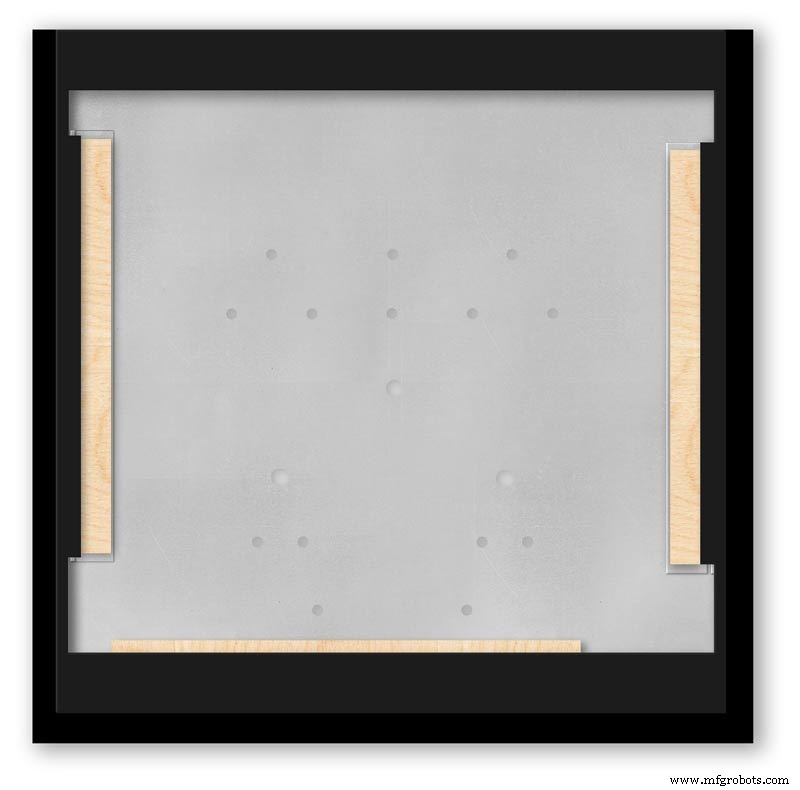
Pic.4 shows the front view with a transparent dial showing mounting locations.
Pic. 5 shows the same but the rear view.
Pic.6 shows the wooden mounting blocks locations and layout.
Pic.7 shows the modules and motors mounted on the blocks.
Step 16:Construction LED Fixing

The 3mm LEDs are mounted so they just show above the surface of the dial pic.1.
3mm holes are drilled and hot melt glue holds them in place.
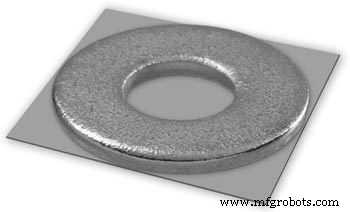
To get a uniform depth I made a jig using a washer and piece of card glued to it pic.2.When fixing the LEDs the jig is pressed against the dial with the depth of the washer setting the protrusion of the LED through the dial.
Step 17:Construction Classic Style English Dial Clock Case
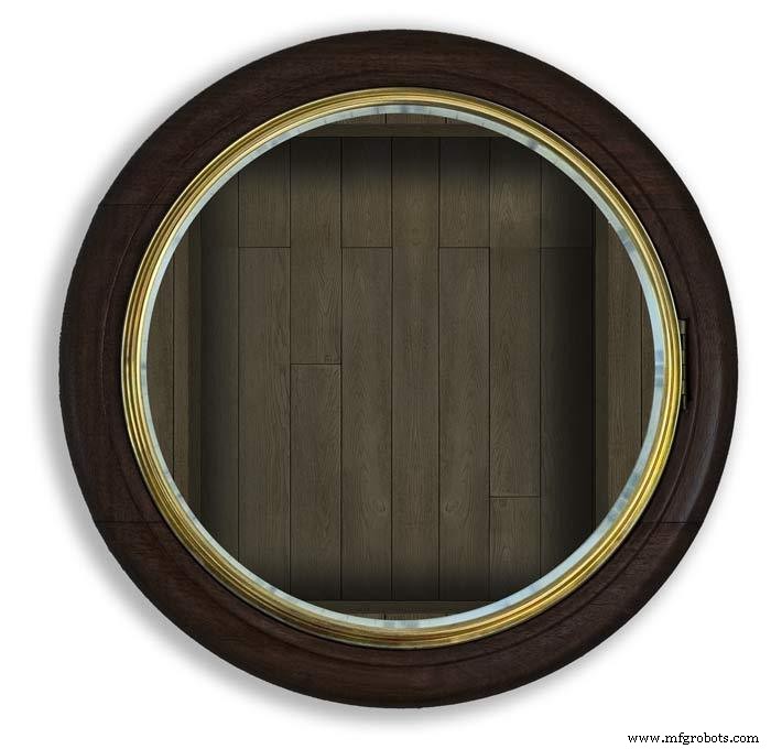

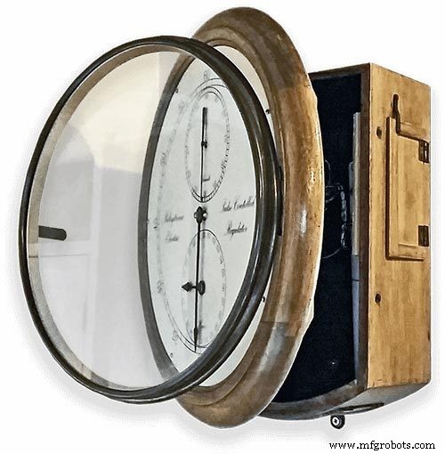
The classic 12" Dial Clock case can be purchased from Ebay as "case only" pic.1.
Various styles are available this one is oak and has a dial surround that hinges away from the back box pic.2.
This makes for a very easy build as all the hard work has been done. The dial is mounted by 3 small wood screws hidden behind the brass dial bezel.
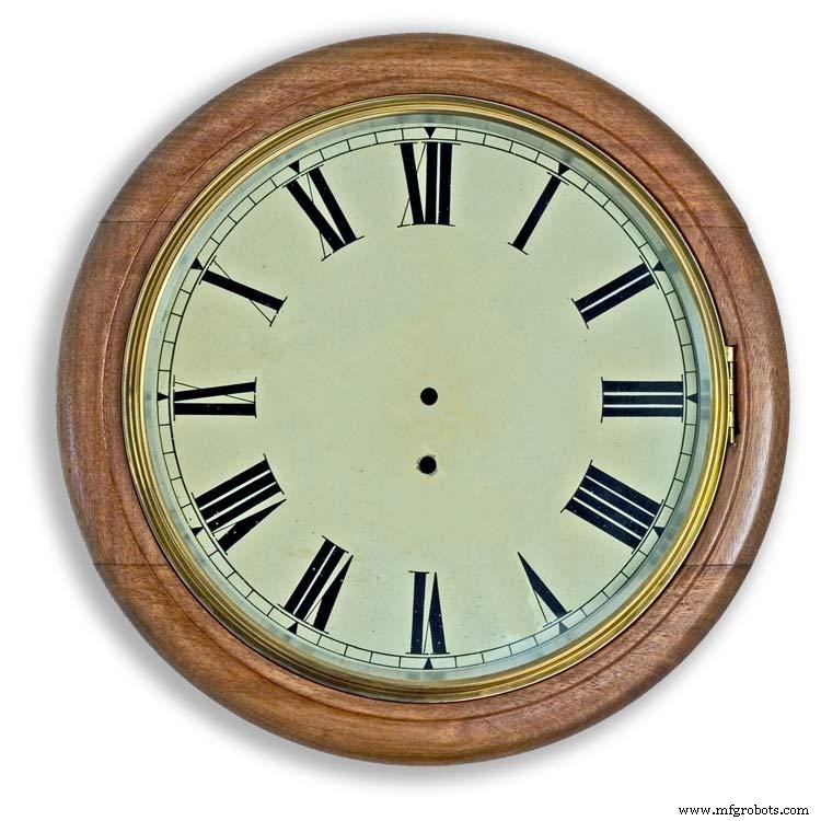
This dial surround has been stripped and bleached to bring out the original light colour of the wood pic.3.The dial was removed as it had a winding hole off center.
A new dial was cut from a sheet of alluminium pic.4.
Pic.5 side view of the Barometer showing the back box.
Pic.6 shows my regulator clock case with original curved back box, hinged dial bezel and pegged dial surround.
Many of these clock cases were held in place by four wooden pegs. If your case is constructed like this add a pair of hinges to one side and use the remaining two pegs to lock the dial surround in place.
Step 18:Construction Modern Case


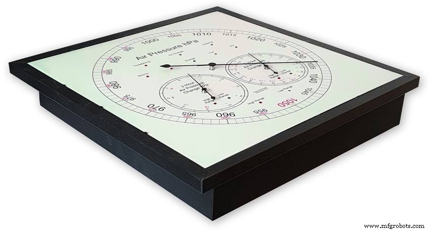
Picture Frame Version
I have used two identical picture frames mounted back to back. These frames are 30cm x 30cm approx. 12"x12" pic.1.
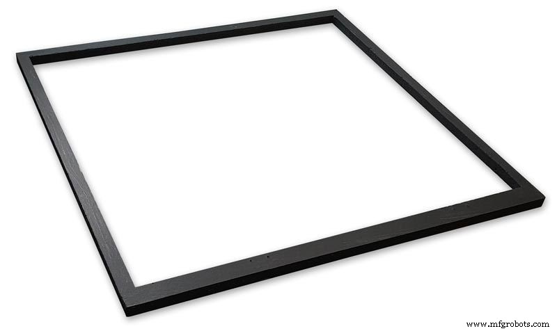
pic.2 Frames are joined back to back.
pic.3 This gives a double depth frame.
pic.4 Rear side view showing wired boards and modules.
pic.5 The dial viewed through the rear frame.
pic.6 Rear half of the frame with all wiring in place.
pic.7 The front of the dial now shows through the front half of the frame. Wooden bevels hide the space behind the front half of the frame.
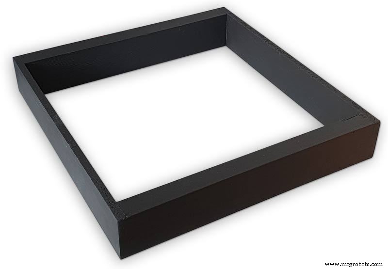
Step 19:Construction Modern Case Backbox
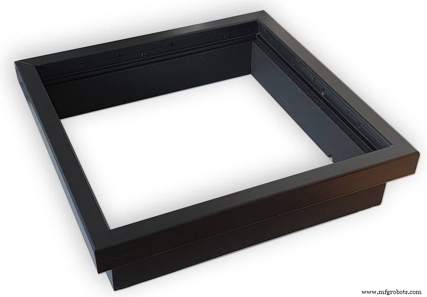
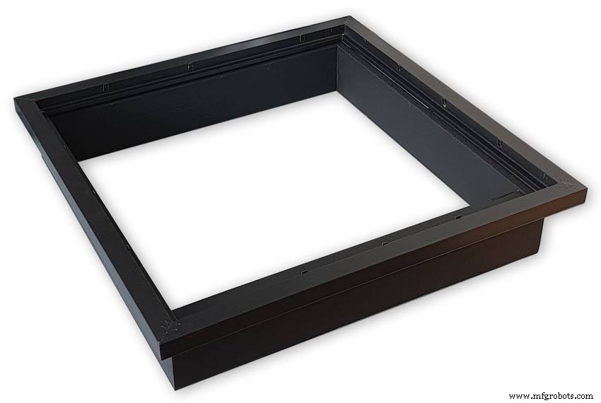


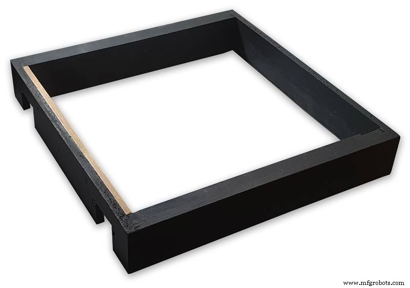
Back Box
Pic.1 The barometer is housed in a back box that is smaller than the dial frame on all side apart from the top. The fram overlap helps hide the back box and adds a shadow effect to the case on the wall.
Pic.2 The back box is 50mm deep and is simply constructed of glued and screwed wood.
Pic.3 Rear view of back box in position behind rear dial frame showing the frame overlap.
Pic.4 The screw holes are filled then a coat of matt black is applied to the back box.
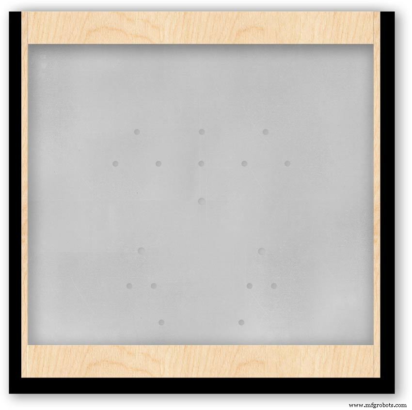
Pic.5 Back box with rear picture frame in place this holds the dial.Note the rear frame is placed upside down.
Pic.6 A spacer is cut the same size and depth as the recess of the picture frame.
Pic.7 The spacer is set under the dial.
Pic.8 This will raise the dial level with the top edge of the rear frame.
Pic.9 Back box with front picture frame in place on top of the rear frame.This frame holds the glass.
Step 20:Construction Modern Case Wall Mounting
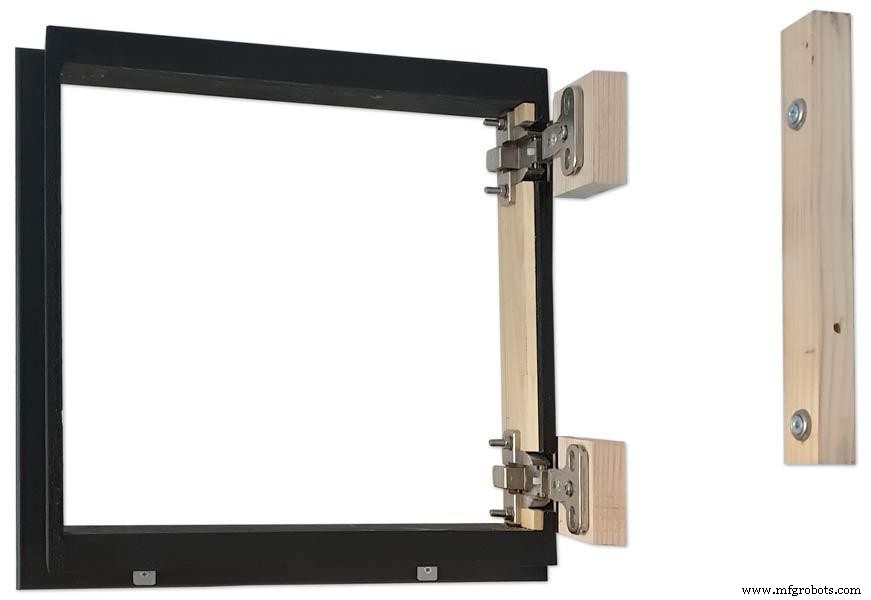


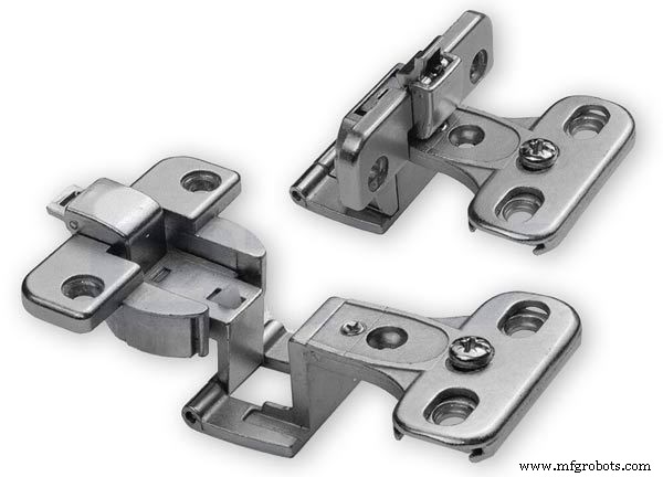
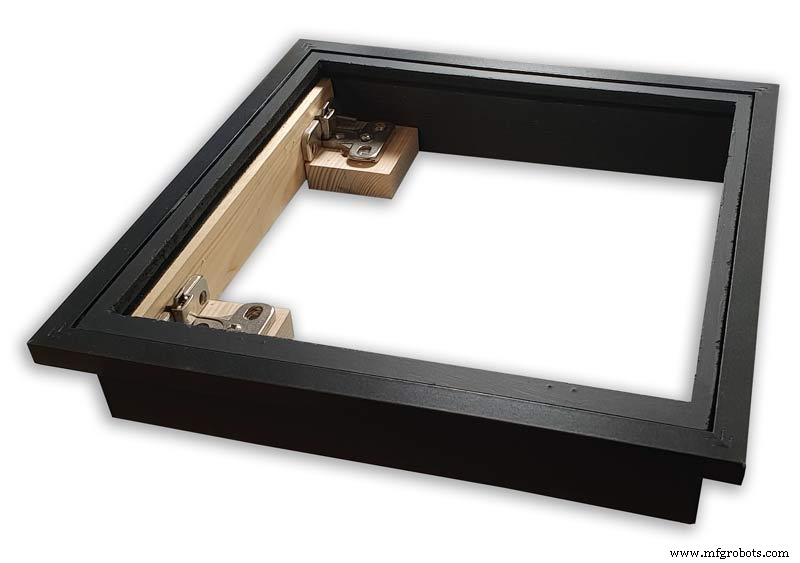
Mounting the Barometer
Pic.1 To allow access to the rear of the Barometer I have mounted it on a pair of GTV 270° inset hinges. The hinges are mounted on a block of wood fixed to the wall and allow the barometer to be swung out for access. The hinges also have a quick release function if the Barometer needs to be taken down for maintenance at any time. The hinge pivot is set back which also allows the top of the case to clear the wall when hinged out.
Pic.2 The hinges are mounted on wooden blocks screwed to the wall.
Pic.3 I have screwed and glued an extra piece of timber to the left hand side where the hinges will mount.This will add strength as all the weight of the clock will be on this side when the clock case is open. Two aluminium plates will cover the hinge holes.
Pic.4 Hinge blocks in place. Note these are bolted through the case rather than screwed.
Pic.5 Back Box mounted on the wall. The fixing screws also hold the hinge to the wooden mounting blocks The wooden baton on the right is also fixed to the wall and supports the top right hand corner of the back box. It also serves as a fixing point for the wall mount locking pins that holds the back box shut against the wall.
Pic.6 The back box is shown open with the wooden mounting blocks and batons fixed to the wall. The hole in the front edge of the baton aligns with a hole in the side of the back box. A steel pin is inserted here to lock the barometer shut against the wall.
Pic.7 Back box open allowing access to the LCD displays and setting switches.
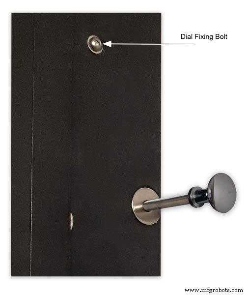
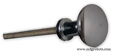
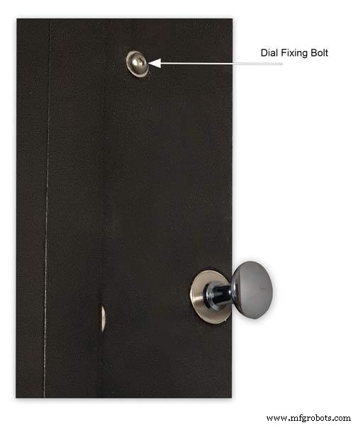
Pic.8 Steel Locking Pin This is a small cabinet knob with a length of treaded bar screwed into the thread.
Pic.9 &10 The locking pin when pushed fully in lock the barometer against the wall. When pulled out the barometer is able to swing out to allow access to the control switched and LCD displays.
Pic.11 Detail of Locking Pin and location of right side dial fixing bolt. I have glued a washer in place over the hole as an escutcheon plate.
Step 21:Construction Modern Case Dial Mounting


The dial and all the boards etc are removable for maintenance and is held to the backbox by 2 bolts.
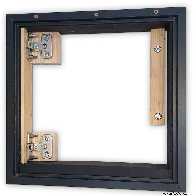
Mounting the Dial in the Back Box
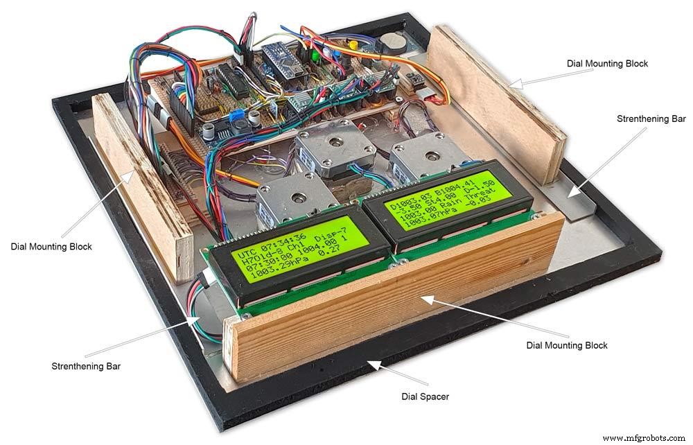
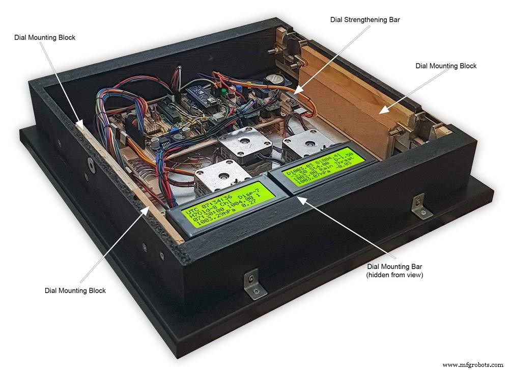
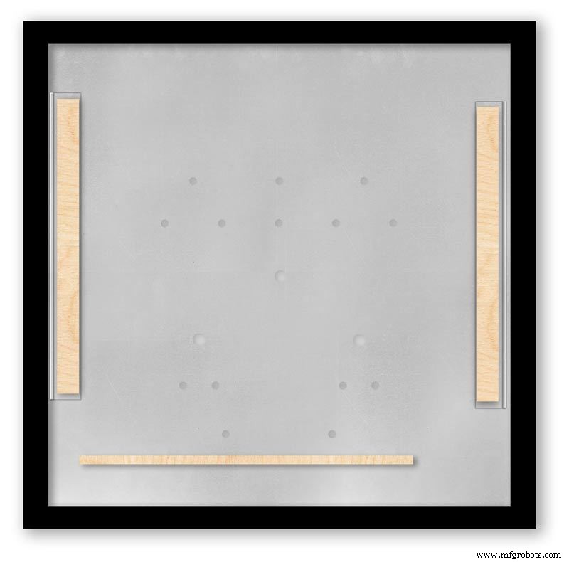
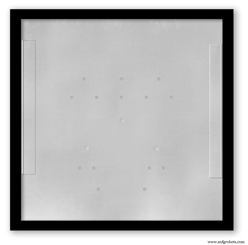
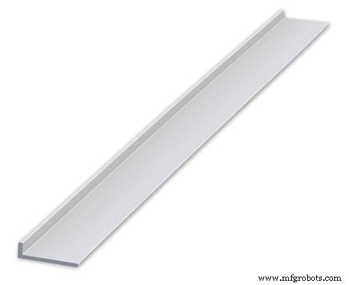
The dial holds the combined weight of all the stepper motors, boards and modules and is stiffened by impact gluing two strips of unequal aluminium angle to it's rear surface.Two blocks of wood are then glued to these bars and small screws then hold these wooden blocks through the side of the back box. A further thin strip of wood is glued to the dial below the LCD mounting block. This is not screwed to the case but sits on the back box to support the dial.
Pic.1 Strengthening bar of alluminium unequal angle.
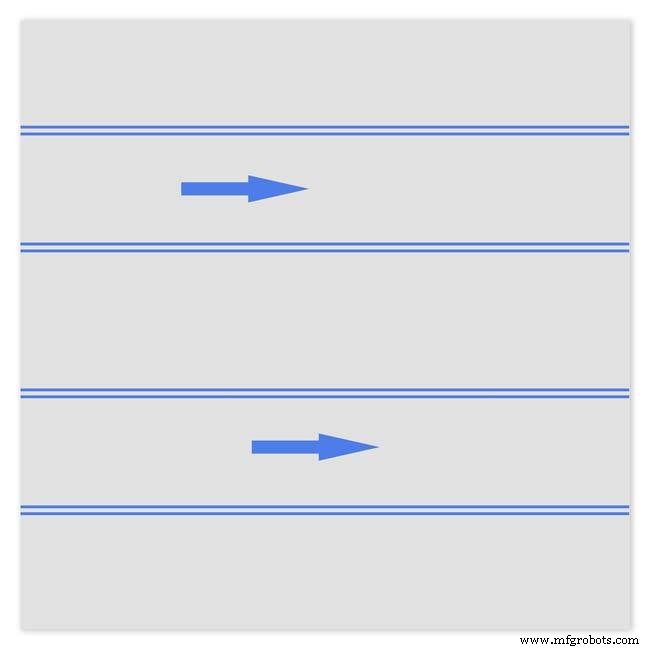
Pic.2 Strengthening bar locations.
Pic.3 Glued wooden fixing/support blocks for dial fixing bolts left and right and glued dial support lower.
Pic.4 Shows contact/fixing points between the back box and dial. Back box in black with dial fixings/support in wood.
Pic.5 Rear view showing mounting block and bar locations.
Pic.6 Dial with Back Box Removed showing mounting blocks and strengthening bars glued to the rear of the dial.
The dial spacer allows the dial to sit flush with the top of the rear picture frame.
Pic.7 Right side of clock showing dial fixing bolt location.
Pic.8 A mount is constructed from 4 thin strips of wood and is placed in the recess of the front picture frame. This fills the gap between the picture frame and dial, holds the Perspex sheet in place and also adds a photo mount effect to the dial.
Pic.9 Mount in place behind the front picture frame.
Step 22:Contruction Dial
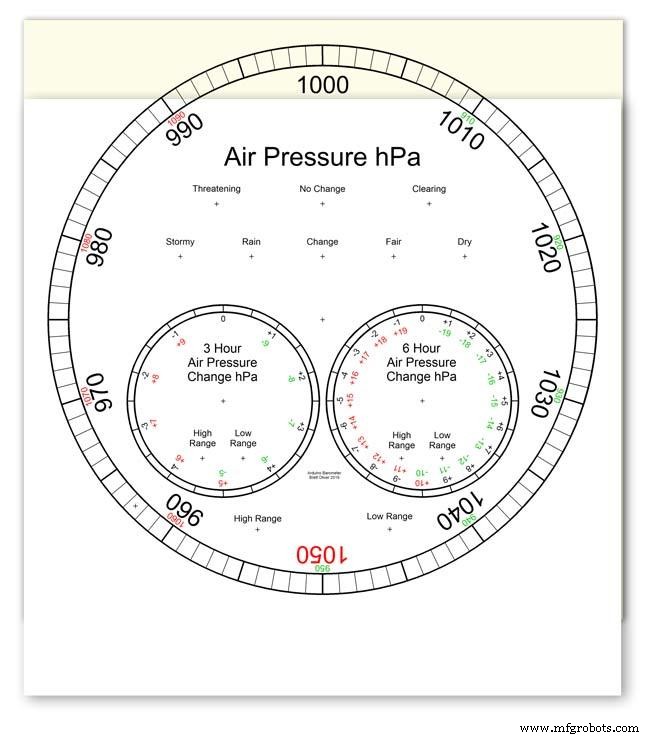
Pic.1 The dial is made from 1.5mm thick alluminium sheet and comes covered with a protective plastic film.
Pic.2 From your cad program print out the dial on A3 paper and include center marks for all the LED and stepper motor shaft holes.This will be your drill template.Lay the paper of the alluminium dial blank and tape the edges to stop it moving.Center punch all the holes through the paper.
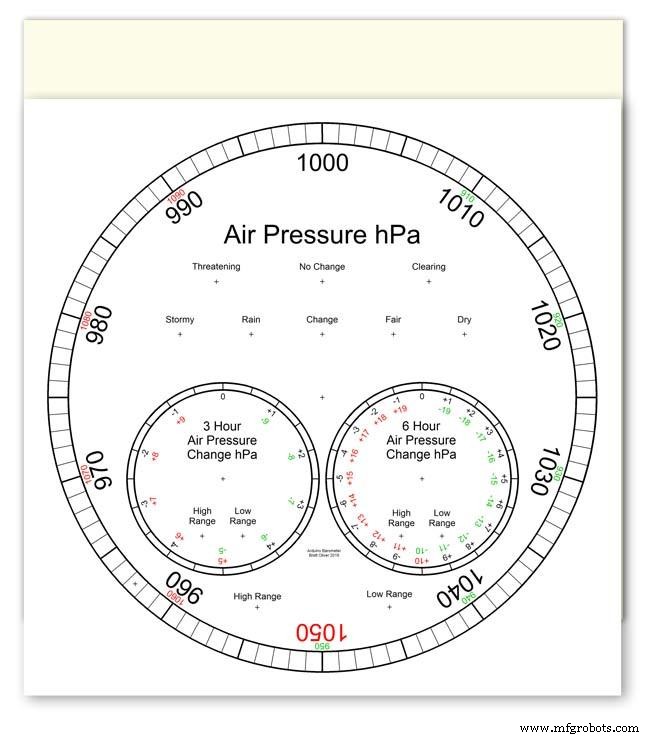
Pic.3 Remove the paper template and drill out the holes 3mm for the LEDs and 3 larger holes for your stepper motor spindle.
Start with a small pilot hole and increase the drill size in 3 stages. If you are using a round dial mark it out on the projective film with a market pen and cut it out at this stage.
Pic.4 The protective plastic film can now be removed. Rub down the dial back and front to remove any burrs and to provide a key for the paint.
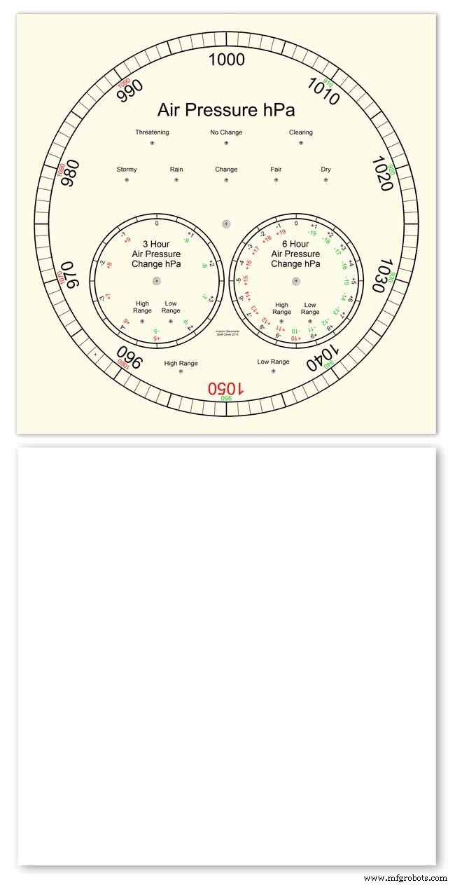
Pic.5 Spray a coat of acrylic primer and then your choice of top coat - I have used antique white.
I then give a final coat of matt clear acrylic. Leave to dry over night.
I have included a high res pic of the dial pic.6. Contact me if you need it in another format. My CAD format is TurboCad.
Step 23:Construction Dial Decal
Apply the water slide decal transfer.
I use Water Slide Decal paper from BIGBITE Studio They have some good tutorials on their site. https://www.bigbitestudio.co.uk/tutorials/water-decal-tutorials/
Pic.1 Water slide decals are printed out on an inkjet printer soaked in water then slid into place. They give a very detailed print and once given a coat of varnish are tough.
Don't forget to order transparent transfers so the dial colour can be seen through the transfer.Follow the instructions with the pack as they do vary.
Pic.2 On my transfers I print out the dial on transfer paper let it dry and then cut it out to just under the size of the dial. I then give it a coat of acrylic varnish.
I set my printer as follows:Plain Paper, Photo &High Speed Off This stops my printer from over inking the paper When the varnish is dry the transfer is soaked in water until the transparent transfer comes away from the white backing sheet.
Pic.3 Move the soaked transfer over the dial.
Pic.4 Slide the transfer into position.
Pic.5 Gently pull the white backing paper backward while holding the transfer down.
Make sure the crosses line up with the center of all the holes.
Pic.6 Get rid of any air bubbles.
Pic.7 Then leave it to dry before adding a coat of matt varnish.
After the coat of varnish break through the layer of transfer over the holes using the back of a drill bit jus smaller than the holes. Then give a final coat of varnish to seal the edges around the holes.
Step 24:Construction Hands

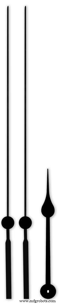


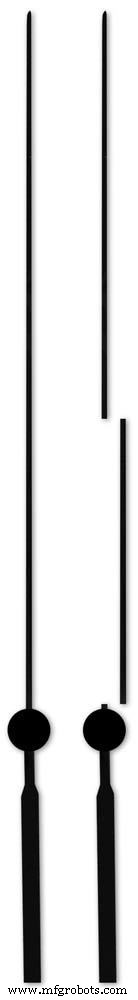
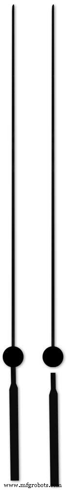
Hands are a very personnal choice and there are many diffent styles to choose from. The hardest part is finding hands that match each other. I found a perfect set of small hands but was unable to find a matching longhand for the main barometer. In the end I made my own from 3 donor hands.
All my hands were quartz second hands so I hand to file the mounting spindle off the back for mounting on the stepper motor spindle.
On some stepper motors the spindle can be drilled out to take the hand spindle but my spindles were too hard to drill.
Pic.1 my completed hands.
Pic.2 The long barometer hand was constructed from 3 different hands
Pic.3 To get the lower spade balance part of the hand I used a spade hand.
Pic.4 First I cut off the top using sharp scissors.
Pic.5 The top was then trimmed by cutting the point off.
Pic.6 The remaining part was then filed away to match the shape of the 2 smaller hands.
Pic.7 The completed balance for the hand.
Pic.8 To make the front pointer and center I cut the end off one off my donor hands.
Pic.9 To make the rear balance shaft I cut a section out of the 3rd donor hand.
Pic.10 Left the 3 parts of the new hand. Middle shows the overlap of the balance shaft to allow for bonding. Right pic shows the balance shaft bonded with impact adhesive to the underside of the balance and center shaft.
To fix the hands to the stepper motor spindle I did not want to use impact adhesive as the hands are fragile and would be damaged if I hand to remove them. In the end I went for a tiny bit of Blu Tack on each hand. Blu Tack is putty like and is non setting but seems to hold very well!
Step 25:Construction Schematic
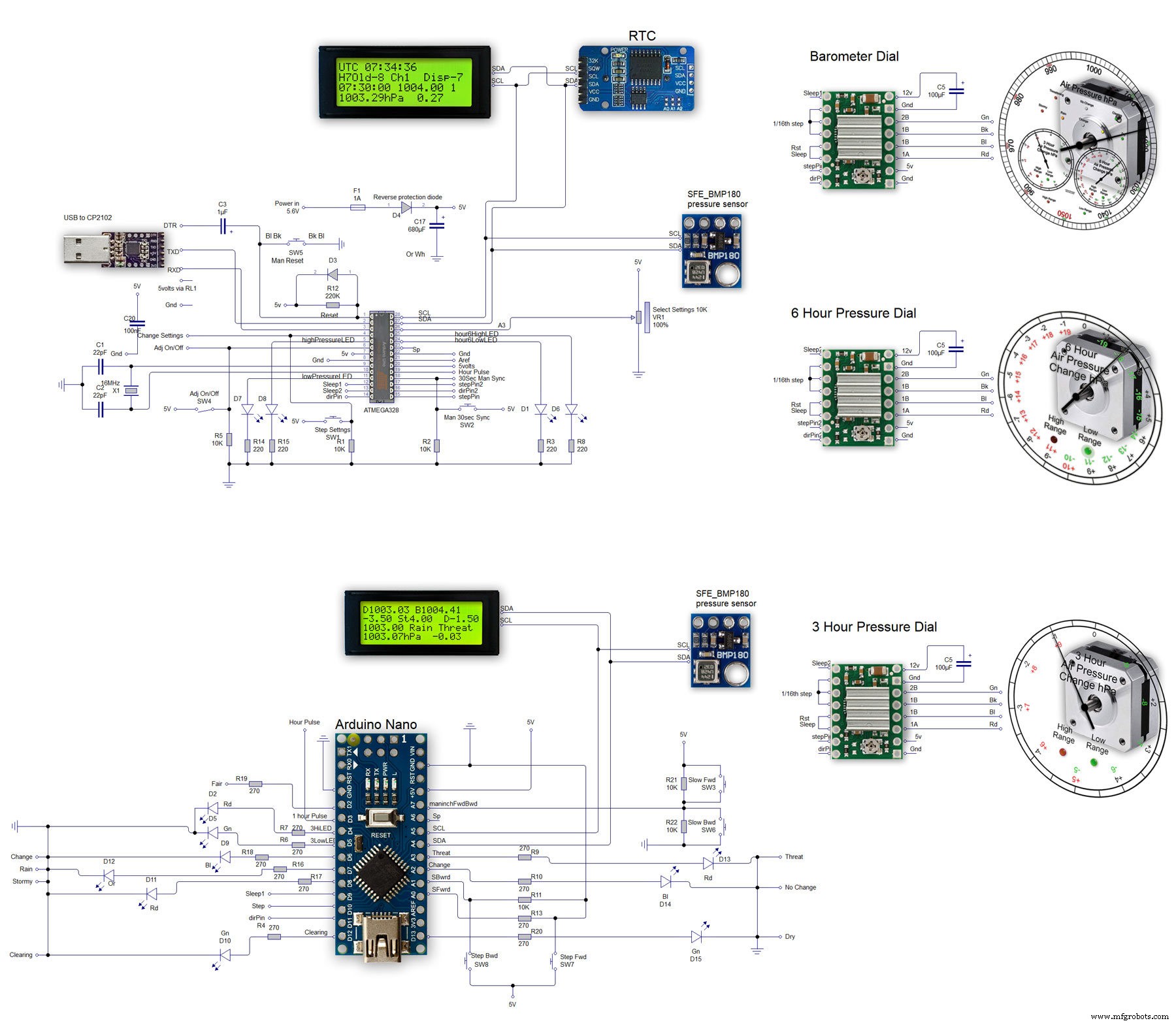
The main shematic is shown in Pic. 1 with the power supply in Pic.2.
You will also need a regulated plug in 12v supply adaptor of around 1amp.
Note I have fitted switches on the LCD displays to turn the backlight LEDs On and Off. This is optional but as the displays are not visible for 99.99% of the time it will save power.
Note larger schematics can be found on my web site here
Step 26:Construction Vero Board
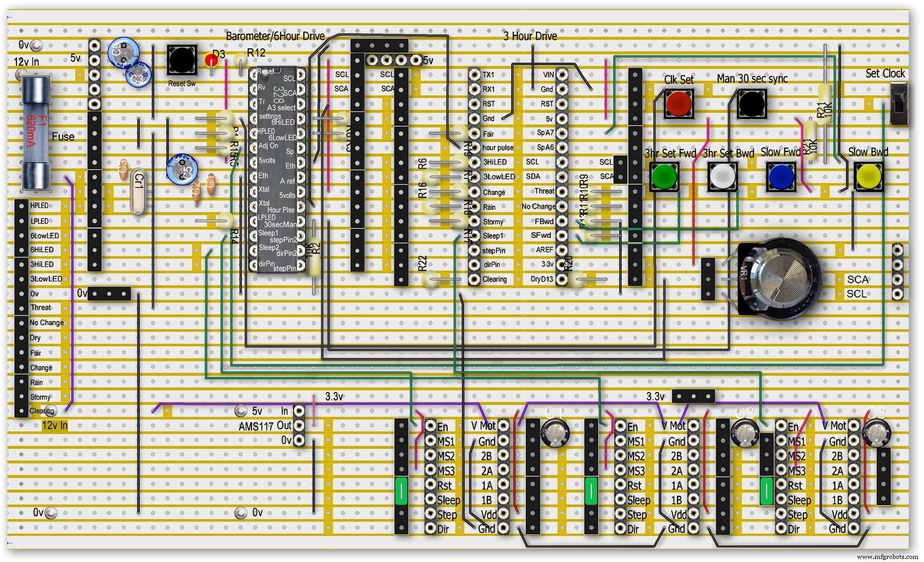
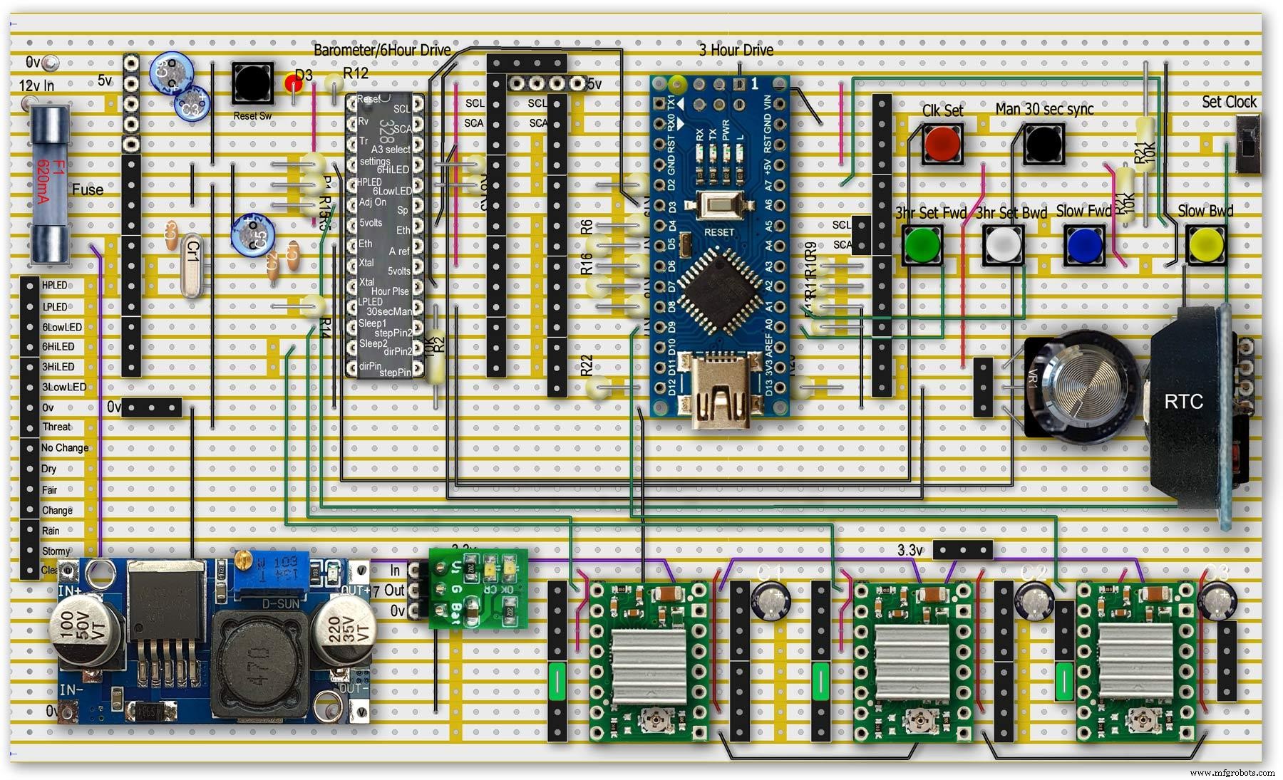
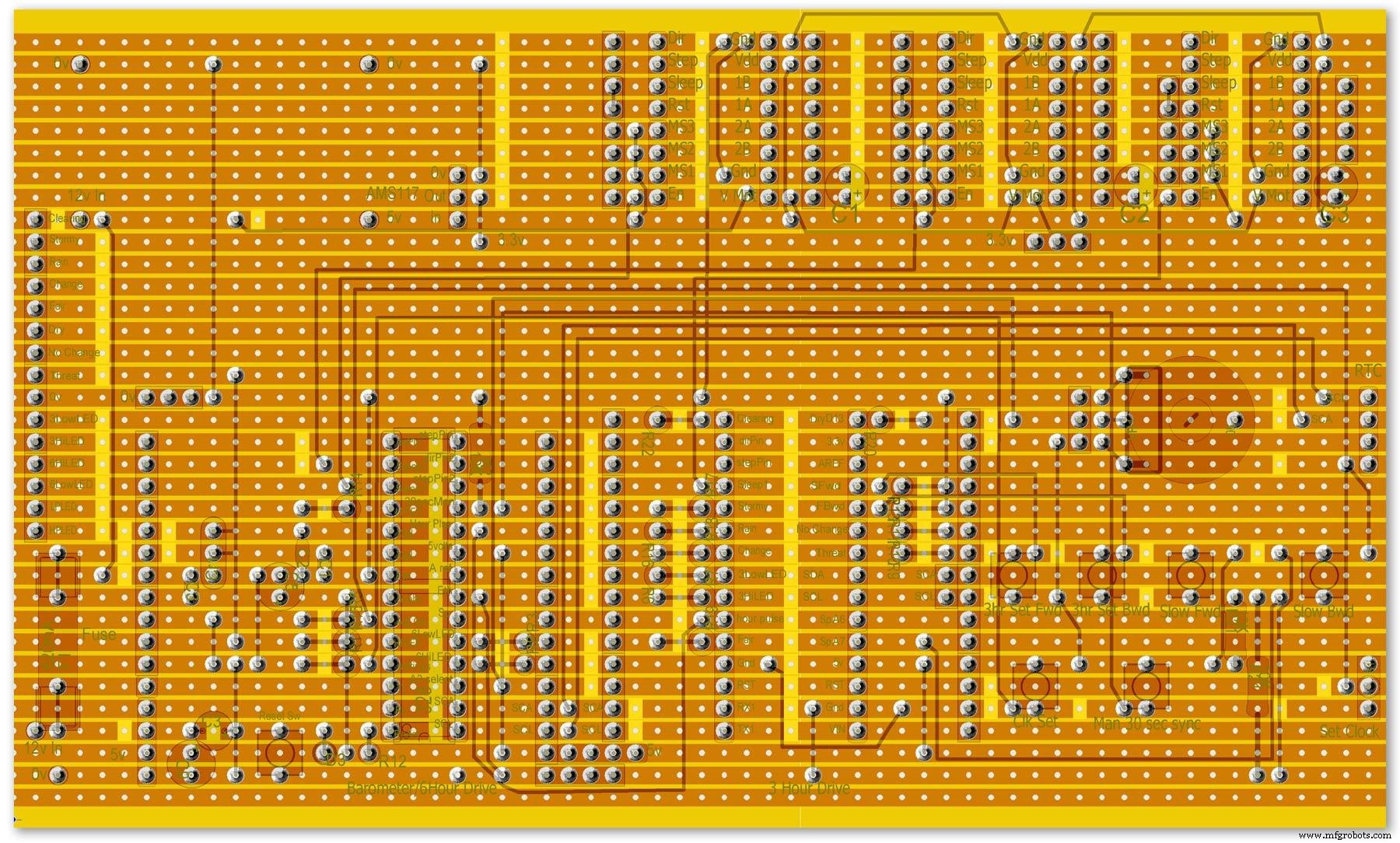
Vero Board Layouts
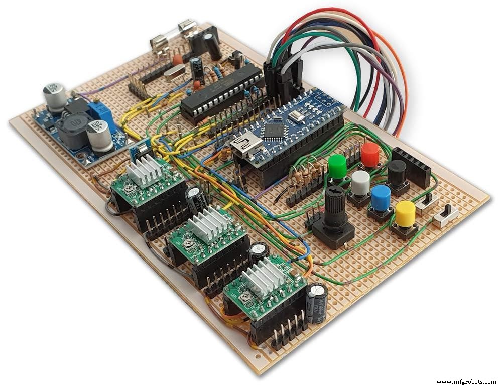
Pic.1 Vero Board with all modules removed.
Pic.2 Vero Board with modules in place.
Pic.3 Vero Board rear view (flipped down from top).
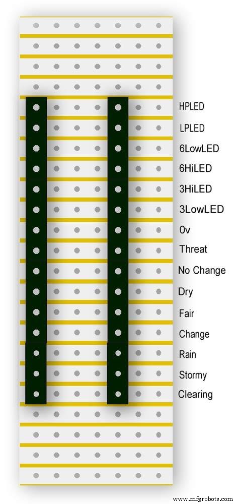
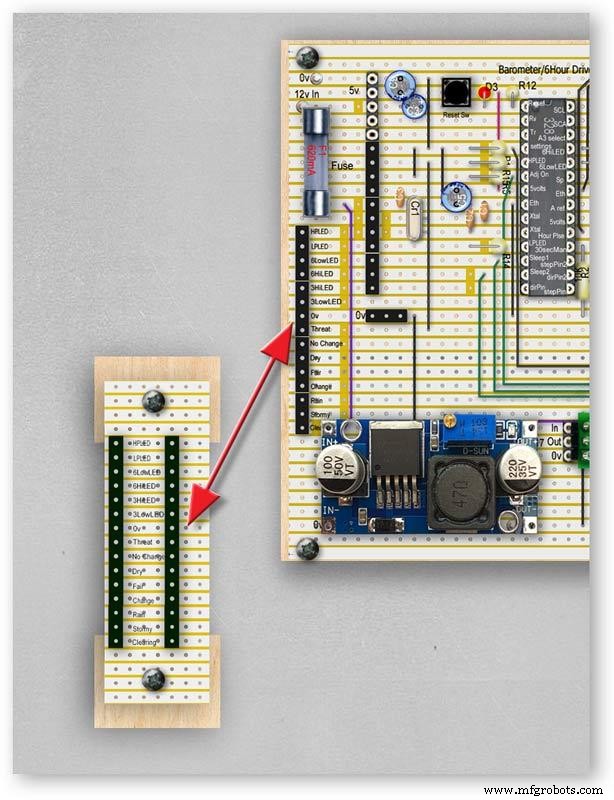
Pic.4 LED Vero Board
This board is used as a connection point for the dial LEDs. This allows the dial to be disconnected from the main board if required for maintenance.
Pic.5 The LED Vero Board connects to the main board with Dupont sockets and male Dupont cable
Pic.6 Vero Board wiring in progress.
Pic.7 Vero Boards and module location on the rear of the dial.
Step 27:Code
Code
There are 2 parts to the code 1 for the Main Barometer Code and 6 hour display and 1 for the 3 hour display and weather forecast.
Step 28:Time-Lapse Video
Time-Lapse Video showing rain radar and the Barometer predicting rain and a storm.
This is a 4K video so you should be able to see full details of the dial and forecast LEDs.
/* Example sketch to control a 28BYJ-48 stepper motor with ULN2003 driver board, AccelStepper and Arduino UNO:number of steps/revolutions. More info:https://www.makerguides.com v4 moved step 6 hour pressure step from void getpressure 1523 to main loop check every hour 365v5 remove unwamted step elementsv6 convert to diff display on 6 hr motorv8 modified hour change formula 1486v9 sleepv10 chnged high/low for EN control v11 chenge calc for hour change 1380v12 added calcCurrentDisp (); to calc current time from line 1384v13 removed 30 sec syncv14 air pressure extremes LEDsv15 add hour diff hour calc etc to row 1 when not on settingsv16 adding 16th stepsv17 errorv18 change min pulse to hour pulse on the hour + 1minv19 check enable and sleepsv20 added DAC to NANO so pins changed on 328 to match (analogue and digital swapped A6 D3 - deleted v20 also changed Low range hi range to both light above 19 or -19v21 same as 20 with serial print removedv23 notes added LCD display info added to startup */#include//SFE_BMP180 pressure sensor#include #include #include // ######## You will need to create an SFE_BMP180 object, here called "pressure":SFE_BMP180 pressure;#define ALTITUDE 118.0 // Altitude of Kenley Surrey in meters// also used to adjust/sync/calibrate to nearby weather station/3 hour display//#########//**********************// set the LCD address to 0x27 for a 20 chars 4 line display// Set the pins on the I2C chip us ed for LCD connections:// addr, en,rw,rs,d4,d5,d6,d7,bl,blpolLiquidCrystal_I2C lcd(0x27, 2, 1, 0, 4, 5, 6, 7, 3, POSITIVE); // Set the LCD I2C address#define DS3231_I2C_ADDRESS 0x68// Convert normal decimal numbers to binary coded decimalbyte decToBcd(byte val){ return( (val/10*16) + (val%10) );}// Convert binary coded decimal to normal decimal numbersbyte bcdToDec(byte val){ return( (val/16*10) + (val%16) );}// Include the AccelStepper library:#include // Define stepper motor connections and motor interface type. Motor interface type must be set to 1 when using a driver:#define dirPin 8#define stepPin 9#define dirPin2 10#define stepPin2 11#define motorInterfaceType 1// Create a new instance of the AccelStepper class:AccelStepper stepper =AccelStepper(motorInterfaceType, stepPin, dirPin);//barometer motorAccelStepper stepper2 =AccelStepper(motorInterfaceType, stepPin2, dirPin2);// 6 hour motorfloat seaPressure =0;float pressureNow =0;float pressurePrevious =0;float pressureDiff =0;int checkStop =0;int pressureRndDiff =0;int pressureRndNow =0;int pressureRndPrevious =0;int adjustOn =4; // allows adjustment of barometer// int test =0; // test mode 0 off 1 is onchar status; double T,P,a;//int h =0;//int m =0;//int j =0;int stepcount =0;int time =0;int resetmins =1;int secondNow =0;int secondPrevious=0;int minuteNow =0;int minutePrevious=0;int hourNow =0;int hourPrevious=0;int hourNow1=0;int hourPrevious1=0;int initial =0;int initial1 =0;int initial3 =0;int highPressureLED =3;int lowPressureLED =5;int hour6LowLED =15;int hour6HighLED =16;int manSync =12; // resets seconds to 30 secondsint changeSetting =2;int syncStop =0;int sync30Stop =0;int stepoffHour =0;int stepoffHourbkw =0;int stepoffMin =0;int stepoffMinbwd =0;int stepoffRTCminfwd =0;int stepoffRTCminbwd =0;int stepoffRTChourfwd =0;int stepoffRTChourbwd =0;int settingreadPin =A3; //Pin for sensing analogue value from potint settingVal =0; // Analogue value 0-1023int LCDstop =0; // stops settings on LCD display refreshing until they changeint hourPulse =13; //min pulse for seconds display was 14int adjustLock =0; // turns off adjust lockint hourcalc =0; // number from 0 to 7 representing the 8 hours of stored pressure readings int hourDiff =0; // used to check if 6hour previous motor should be stepped.int hourChange =0; // the amount of 6 hour to stepint currentDisplay =0; //current 6hour change readingint hour0 =1013; // you can set last 8 hours pressure here or leave at 0 and theint hour1 =1014; // readings will catch up over the next 8 hoursint hour2 =1015;int hour3 =1016;int hour4 =1016;int hour5 =1016;int hour6 =1012;int hour7 =1013;int sleep1 =6;int sleep2 =7;// check air pressure here https://www.meteoplug.com/cgi-bin/meteochart.cgi?draw=a3aeaaa1acbdf9f1fcfed4fedbc2c094c0d6d6d1d2c5edcebbfee9ffeff1fbf9//int Disp3hrIn =A3;//int Disp3hrVal =0;void setup() { pinMode(adjustOn, INPUT); pinMode(hourPulse, OUTPUT); pinMode(highPressureLED, OUTPUT); pinMode(lowPressureLED, OUTPUT); pinMode(hour6LowLED, OUTPUT); pinMode(hour6HighLED, OUTPUT); pinMode(manSync, INPUT); pinMode(sleep1, OUTPUT); pinMode(sleep2, OUTPUT); pinMode(settingreadPin, INPUT); // Set the maximum steps per second:stepper.setMaxSpeed(1000); stepper2.setMaxSpeed(1000); lcd.begin(20,4); // initialize the lcd for 20 chars 4 lines, turn on backlight lcd.backlight(); // backlight on not needed as man controlled lcd.setCursor(0,0); //Start at character 0 on line 0 lcd.print("Barometer A988"); //@@@@@@@@@@@@@@@@@@@@@@@@@@@@@@@@@@@@@@@@@@@@@@@@@@@@@@@@@@@@@@@@@@@@@@@@@@@@@@@@@@@@@@@@@@@@@@@@@@@@@@@@@@@@@@@@@@@@@@@@@@@@@@@@ lcd.setCursor(0,1); //Start at character 0 on line 1 lcd.print(" Version 23"); //@@@@@@@@@@@@@@@@@@@@@@@@@@@@@@@@@@@@@@@@@@@@@@@@@@@@@@@@@@@@@@@@@@@@@@@@@@@@@@@@@@@@@@@@@@@@@@@@@@@@@@@@@@@@@@@@@@@@@@@@@@@@@@@@ { Wire.begin(); Serial.begin(9600); // set the initial time here:// DS3231 seconds, minutes, hours, day, date, month, year // setDS3231time(10,42,9,5,18,12,19);//delay(2000);lcd.clear();}Serial.println("REBOOT");// serial removed // Initialize the sensor (it is important to get calibration values stored on the device). if (pressure.begin()) Serial.println("BMP180 init success");// serial removed else { // Oops, something went wrong, this is usually a connection problem, // see the comments at the top of this sketch for the proper connections. Serial.println("BMP180 init fail\n\n");// serial removed while(1); // Pause forever. } //LED TestdigitalWrite(hour6HighLED, HIGH);delay (500);digitalWrite(hour6HighLED, LOW);digitalWrite(hour6LowLED, HIGH);delay (500);digitalWrite(hour6LowLED, LOW);digitalWrite(highPressureLED, HIGH);delay (500);digitalWrite(highPressureLED, LOW);digitalWrite(lowPressureLED, HIGH);delay (500);digitalWrite(lowPressureLED, LOW);delay (500);lcd.clear();getPressure ();// gets all pressure readings// Disp readings on startup so hands can be set lcd.setCursor(0,1); lcd.print(""); lcd.setCursor(0,1); lcd.print("H"); lcd.print(hourcalc); lcd.setCursor(2,1); lcd.print(""); lcd.setCursor(2,1); lcd.print("Old"); lcd.print(currentDisplay); lcd.setCursor(13,1); lcd.print(""); lcd.setCursor(13,1); lcd.print("Disp"); lcd.print(hourDiff); //disable motors on startupdigitalWrite(sleep1, HIGH);digitalWrite(sleep2, HIGH);stepper.disableOutputs();stepper2.disableOutputs();// test =1; // test set to 0 off 1 on}void loop() { if( digitalRead(adjustOn) ==HIGH || adjustLock ==1)// only alow settings when change settings switch is ON{ //digitalWrite(sleep1, LOW);//enable on //digitalWrite(sleep2, LOW);//enable on only enable outputs for 2 mins Settings(); //set what function the setiing switches have adjustLock =1; //hold on adjustment if( digitalRead(adjustOn) ==LOW){//digitalWrite(sleep1, HIGH);//disable on//digitalWrite(sleep2, HIGH);//enable on only enable outputs for 2 minsadjustLock =0; //hold on adjustment } }// only allow settings change when setting switch is on // displayTime(); // display the real-time clock data on the Serial Monitor, byte second, minute, hour, dayOfWeek, dayOfMonth, month, year; // retrieve data from DS3231 readDS3231time(&second, &minute, &hour, &dayOfWeek, &dayOfMonth, &month, &year);//@@@@@@@@@@@@@@@@@@@@@@@@@@@@@@@@@@@@@@@@@@@@@@@@@@@@@@@@@@@@@@@@@@@@@@@@@@@@@@@@@@@@@@@@@@@@@@@@@@@@@@@@@@@@@@@@@ //enable air pressure readings if (minute ==9 || minute ==19 || minute ==29 || minute ==39 || minute ==49 || minute ==59 &&second ==59) { checkStop =0;// resets checkstop to allow air pressure readings every 10 mins }//check air pressure every 10 mins if (checkStop ==0) { if ( minute ==0 || minute ==10 || minute ==20 || minute ==30 || minute ==40 || minute ==50 ) { //digitalWrite(sleep1, LOW);//enable on -only enable outputs for 1 min // only sleep1 needs activation getPressure ();// gets all pressure readings checkStop =1;// stops multiple readings of air pressure }// else //digitalWrite(sleep1, HIGH);//enable off // Serial.print("Sleep 1 HIGH (off) "); // Serial.println(hourChange); } //@@@@@@@@@@@@@@@@@@@@@@@@@@@@@@@@@@@@@@@@@@@@@@@@@@@@@@@@@@@@@@@@@@@@@@@@@@@@@@@@@@@@@@@@@@@@@@@@@@@@@@@@@@@@@@@@if(digitalRead(manSync)==HIGH)// resets seconds to 30{ setDS3231time(30, minute, hour, dayOfWeek, dayOfMonth, month, year); //Set seconds to 30 on RTC } // counts seconds secondNow =second; if(secondNow!=secondPrevious || initial) { lcd.setCursor(0,0); lcd.print("UTC "); if(hour<10) { lcd.print(0); } lcd.print(hour); lcd.print(":"); if(minute<10) { lcd.print(0); } lcd.print(minute); lcd.print(":"); if(second<10) { lcd.print(0); } lcd.print(second); lcd.print(""); // Serial.print("-1*0 ");// Serial.println(-1*0); initial =0; secondPrevious =secondNow; } // count minutes minuteNow =minute; if(minuteNow!=minutePrevious || initial) //settingVal <690 stops clock motors operating when setting RTC { initial =0; minutePrevious =minuteNow; // digitalWrite(minPulse,HIGH);//1 min pulse for seconds display sync syncStop =0;// clock will not sync again untill a new minute has started. // digitalWrite(minPulse,LOW);//1 min pulse for seconds display sync } // counts hours + 1min for hourPulse at 15 seconds past the hour this allows barometer and 6 hour dial to step first if ( minute ==0 &&second ==15) // send hour pulse 15 seconds past the hour to 3 hour circuit allows other motors to stop { digitalWrite(hourPulse,HIGH); digitalWrite(highPressureLED,HIGH); // Serial.println("hourPulse Hi "); } else if (minute !=1 || second !=0) { digitalWrite(hourPulse,LOW);digitalWrite(highPressureLED,LOW); }// counts hours hourNow =hour; if ((minute ==59 &&second> 50) || (minute ==0 &&second <10) )// allows change on the hour only {// digitalWrite(sleep2, LOW);// enable 6hr motor if(hourNow!=hourPrevious || initial) //settingVal <690 stops clock motors operating when setting RTC { initial =0; hourPrevious =hourNow;//print hour stores every hour // serial removed /* Serial.print("hour0 "); Serial.println(hour0); Serial.print("hour1 "); Serial.println(hour1); Serial.print("hour2 "); Serial.println(hour2); Serial.print("hour3 "); Serial.println(hour3); Serial.print("hour4 "); Serial.println(hour4); Serial.print("hour5 "); Serial.println(hour5); Serial.print("hour6 "); Serial.println(hour6); Serial.print("hour7 "); Serial.println(hour7); */ //##############################################################################//step 6 hour motorif (hourChange> 0 &&hourChange <40) // 6 hour motor will not step if diff> 10 { stephourFwd(); //Serial.print("Step 6 hour Forward ");// serial removed // Serial.println(hourChange);// serial removed hourChange =0; } else if (hourChange <0 &&hourChange> -40) // else if (hourDiff ==-1 || test ==1) { stephourBwd(); // Serial.print("Step 6 Hour Backward ");// serial removed // Serial.println(hourChange);// serial removed hourChange =0; } // hourChange =0; //############################################################################## } // digitalWrite(sleep2, HIGH);// disable 6hr motor// add LCD stop if(second==0) { // lcd.setCursor(0,1); //lcd.print(" "); lcd.setCursor(0,1); lcd.print(""); lcd.setCursor(0,1); lcd.print("H"); lcd.print(hourcalc); lcd.setCursor(2,1); lcd.print(""); lcd.setCursor(2,1); lcd.print("Old"); lcd.print(currentDisplay); lcd.setCursor(13,1); lcd.print(""); lcd.setCursor(13,1); lcd.print("Disp"); lcd.print(hourDiff); } } } // Set Clock/Motors###################################################################################################//gets advance retard settings from potvoid Settings(){ settingVal =analogRead(settingreadPin); // read the value from the pot if ( settingVal>=0 &&settingVal <85 ) { setMinsfwd(); } if ( settingVal>=85 &&settingVal <170 ) { setMinsbwd(); } if ( settingVal>=170 &&settingVal <255 ) { setMinsslowfwd(); } if ( settingVal>=255 &&settingVal <340 ) { setMinsslowbkd(); } if ( settingVal>=340 &&settingVal <425 ) { setHoursfwd(); } if ( settingVal>=425 &&settingVal <510 ) { setHoursbwd(); } if ( settingVal>=510 &&settingVal <595 ) { setHoursslowfwd(); } if ( settingVal>=595 &&settingVal <690 ) { setHourslowbkd(); } if ( settingVal>=690 &&settingVal <765 ) { setRTCfwdmin(); } if ( settingVal>=765 &&settingVal <850 ) { setRTCbwdmin(); } if ( settingVal>=850 &&settingVal <900 ) { setRTCfwd(); } if ( settingVal>=900 &&settingVal <970 ) { setRTCbwd(); }if ( settingVal>=970 &&settingVal <1025 ) { } if ( settingVal>=0 &&settingVal <85 &&LCDstop==0)// LCDstop prevents the LCD from freshing until another item is selected { lcd.setCursor(0,1); lcd.print(""); lcd.setCursor(0,1); lcd.print("Barometer Advance"); LCDstop=1; } if ( settingVal>=85 &&settingVal <170 &&LCDstop==1) { lcd.setCursor(0,1); lcd.print(""); lcd.setCursor(0,1); lcd.print("Barometer Retard"); LCDstop=0; } if ( settingVal>=170 &&settingVal <255 &&LCDstop==0 ) { lcd.setCursor(0,1); lcd.print(""); lcd.setCursor(0,1); lcd.print("Baro Inch Advance"); LCDstop=1; } if ( settingVal>=255 &&settingVal <340 &&LCDstop==1 ) { lcd.setCursor(0,1); lcd.print(""); lcd.setCursor(0,1); lcd.print("Baro Inch Retard"); LCDstop=0; } if ( settingVal>=340 &&settingVal <425 &&LCDstop==0 ) { lcd.setCursor(0,1); lcd.print(""); lcd.setCursor(0,1); lcd.print("6Hr Baro Advance"); LCDstop=1; } if ( settingVal>=425 &&settingVal <510 &&LCDstop==1 ) { lcd.setCursor(0,1); lcd.print(""); lcd.setCursor(0,1); lcd.print("6Hr Baro Retard"); LCDstop=0; } if ( settingVal>=510 &&settingVal <595 &&LCDstop==0 ) { lcd.setCursor(0,1); lcd.print(""); lcd.setCursor(0,1); lcd.print("6Hr Baro Inch Advn"); LCDstop=1; } if ( settingVal>=595 &&settingVal <690 &&LCDstop==1 ) { lcd.setCursor(0,1); lcd.print(""); lcd.setCursor(0,1); lcd.print("6Hr Baro Inch Retard"); LCDstop=0; } if ( settingVal>=690 &&settingVal <765 &&LCDstop==0) { lcd.setCursor(0,1); lcd.print(""); lcd.setCursor(0,1); lcd.print("RTC Min Advance"); LCDstop=1; } if ( settingVal>=765 &&settingVal <850 &&LCDstop==1 ) { lcd.setCursor(0,1); lcd.print(""); lcd.setCursor(0,1); lcd.print("RTC Min Retard"); LCDstop=0; } if ( settingVal>=850 &&settingVal <900 &&LCDstop==0 ) { lcd.setCursor(0,1); lcd.print(""); lcd.setCursor(0,1); lcd.print("RTC Hour Advance"); LCDstop=1; } if ( settingVal>=900 &&settingVal <970 &&LCDstop==1 ) { lcd.setCursor(0,1); lcd.print(""); lcd.setCursor(0,1); lcd.print("RTC Hour Retard"); LCDstop=0; } if ( settingVal>=970 &&settingVal <1025 &&LCDstop==0 ) { lcd.setCursor(0,1); lcd.print(""); lcd.setCursor(0,1); lcd.print("OFF"); LCDstop=1; } }// END of Loop// set RTC min forward 1 min per press ##################################################################################void setRTCfwdmin(){ if( digitalRead(changeSetting) ==HIGH &&stepoffRTCminfwd ==0 ) { byte second, minute, hour, dayOfWeek, dayOfMonth, month, year; // retrieve data from DS3231 readDS3231time(&second, &minute, &hour, &dayOfWeek, &dayOfMonth, &month, &year); minute =minute+1; if (minute ==60) { minute =0; } setDS3231time(second, minute, hour, dayOfWeek, dayOfMonth, month, year); //Set seconds to 30 on RTC stepoffRTCminfwd =1; } if( digitalRead(changeSetting) ==LOW ) { stepoffRTCminfwd =0; }}//##################################################################################// set RTC min backward 1 min per press ##################################################################################void setRTCbwdmin(){ if( digitalRead(changeSetting) ==HIGH &&stepoffRTCminbwd ==0 ) { byte second, minute, hour, dayOfWeek, dayOfMonth, month, year; // retrieve data from DS3231 readDS3231time(&second, &minute, &hour, &dayOfWeek, &dayOfMonth, &month, &year); minute =minute-1; if (minute <1) { minute =59; } setDS3231time(second, minute, hour, dayOfWeek, dayOfMonth, month, year); //Set seconds to 30 on RTC stepoffRTCminbwd =1; } if( digitalRead(changeSetting) ==LOW ) { stepoffRTCminbwd =0; }}//##################################################################################//###################################################################################################// set RTC hour forward 1 hour per press ##################################################################################void setRTCfwd(){ if( digitalRead(changeSetting) ==HIGH &&stepoffRTChourfwd ==0 ) { byte second, minute, hour, dayOfWeek, dayOfMonth, month, year; // retrieve data from DS3231 readDS3231time(&second, &minute, &hour, &dayOfWeek, &dayOfMonth, &month, &year); hour =hour+1; setDS3231time(second, minute, hour, dayOfWeek, dayOfMonth, month, year); //Set seconds to 30 on RTC stepoffRTChourfwd =1; } if( digitalRead(changeSetting) ==LOW ) { stepoffRTChourfwd =0; }}//##################################################################################// set RTC hour backward 1 hour per press ##################################################################################void setRTCbwd(){ if( digitalRead(changeSetting) ==HIGH &&stepoffRTChourbwd ==0 ) { byte second, minute, hour, dayOfWeek, dayOfMonth, month, year; // retrieve data from DS3231 readDS3231time(&second, &minute, &hour, &dayOfWeek, &dayOfMonth, &month, &year); hour =hour-1; setDS3231time(second, minute, hour, dayOfWeek, dayOfMonth, month, year); //Set seconds to 30 on RTC stepoffRTChourbwd =1; } if( digitalRead(changeSetting) ==LOW ) { stepoffRTChourbwd =0; }}//##################################################################################// set Minutes Motor forward 1 min per press ##################################################################################void setMinsfwd(){ //digitalWrite(sleep1, LOW); //stepper.enableOutputs();// step minutes 1 min per press if( digitalRead(changeSetting) ==HIGH &&stepoffMin ==0 ) { //Serial.println("Step Forward Man");// serial removed stepoffMin =1; stepminsFwd(); } if( digitalRead(changeSetting) ==LOW ) { stepoffMin =0; }//digitalWrite(sleep1, HIGH); //stepper.disableOutputs();}//##################################################################################// set Minutes Motor backward 1 min per press ##################################################################################void setMinsbwd(){ //digitalWrite(sleep1, LOW); // stepper.enableOutputs(); if( digitalRead(changeSetting) ==HIGH &&stepoffMinbwd ==0 ) { // Serial.println("Step Backward Man");// serial removed stepoffMinbwd =1; stepminsBwd(); } if( digitalRead(changeSetting) ==LOW ) { stepoffMinbwd =0; }//digitalWrite(sleep1, HIGH); // stepper.disableOutputs();}//##################################################################################// step minutes slow forward const press ##################################################################################void setMinsslowfwd(){ stepper.enableOutputs(); digitalWrite(sleep1, LOW); if( digitalRead(changeSetting) ==HIGH ) { // Serial.println("Step Baro Inch Forward Man");// serial removed stepper.setCurrentPosition(0); // Run the motor forward at 500 steps/second until the motor reaches 4096 steps (1 revolution):while (stepper.currentPosition() !=1) { //was 52 52x60 =3120 stepper.setSpeed(50); stepper.runSpeed(); } /* digitalWrite(motorPin1, LOW); digitalWrite(motorPin2, LOW); digitalWrite(motorPin3, LOW); digitalWrite(motorPin4, LOW);*/ } digitalWrite(sleep1, HIGH); stepper.disableOutputs();}//##################################################################################// step minutes slow backward const press ##################################################################################void setMinsslowbkd(){ stepper.enableOutputs(); digitalWrite(sleep1, LOW); if( digitalRead(changeSetting) ==HIGH ) { // Serial.println("Step Baro Inch Backward Man");// serial removed stepper.setCurrentPosition(0); // Run the motor forward at 500 steps/second until the motor reaches 4096 steps (1 revolution):while (stepper.currentPosition() !=-1) { //was 52 52x60 =3120 stepper.setSpeed(-50); stepper.runSpeed(); } /* digitalWrite(motorPin1, LOW); digitalWrite(motorPin2, LOW); digitalWrite(motorPin3, LOW); digitalWrite(motorPin4, LOW);*/ } digitalWrite(sleep1, HIGH); stepper.disableOutputs();}//##################################################################################// set Hour Motor forward 1 hour per press ##################################################################################void setHoursfwd(){ // stepper2.enableOutputs(); // digitalWrite(sleep2, LOW); // step hours 1 hour per press if( digitalRead(changeSetting) ==HIGH &&stepoffHour ==0 ) { // Serial.println("Step 6hr Forward Man");// serial removed stepoffHour =1; stephourmanFwd(); } // stepper2.disableOutputs(); // digitalWrite(sleep2, HIGH);if( digitalRead(changeSetting) ==LOW ) { stepoffHour =0; }...This file has been truncated, please download it to see its full contents.
/* Example sketch to control a 28BYJ-48 stepper motor with ULN2003 driver board, AccelStepper and Arduino UNO:number of steps/revolutions. More info:https://www.makerguides.com v4 added presure extreme LEDsv5 add forcast LEDs and calcv6 sorted enable and sleep orderv7 remove adjust on and test replace it with Clearing and threatening LEDs PIN 12 and 13 v8 add dac driver-deletedv9 added LCDv10 added weather forecast usingLEDs v12 LEds test addedv13 add 1 dp point to 3 hour displayv14 void 1026 add slow set buttonsv18 voided v19last reading not included in number of stepsv20 change led test orderv20a serial.print removed indicated by // serial removedv21 as 20a identical to v20 that includes serial print*/#include//SFE_BMP180 pressure sensor#include #include // ######## You will need to create an SFE_BMP180 object, here called "pressure":SFE_BMP180 pressure;#define ALTITUDE 125.0 // Altitude of Kenley Surrey in meters//#########//**********************// set the LCD address to 0x27 for a 20 chars 4 line display// Set the pins on the I2C chip used for LCD connections:// addr, en,r w,rs,d4,d5,d6,d7,bl,blpolLiquidCrystal_I2C lcd(0x27, 2, 1, 0, 4, 5, 6, 7, 3, POSITIVE); // Set the LCD I2C address//#define DS3231_I2C_ADDRESS 0x68// Convert normal decimal numbers to binary coded decimalbyte decToBcd(byte val){ return( (val/10*16) + (val%10) );}// Convert binary coded decimal to normal decimal numbersbyte bcdToDec(byte val){ return( (val/16*10) + (val%16) );}// Include the AccelStepper library:#include // Define stepper motor connections and motor interface type. Motor interface type must be set to 1 when using a driver:#define dirPin 11#define stepPin 10#define motorInterfaceType 1// Create a new instance of the AccelStepper class:AccelStepper stepper =AccelStepper(motorInterfaceType, stepPin, dirPin);float seaPressure =0;float pressureNow =0;float pressurePrevious =0;float pressureDiff =0;int checkStop =0;//int pressureRndDiff =0;int pressureRndNow =0;int pressureRndPrevious =0;int adjustOn =12; // allows adjustment of barometer// int test =0; // test mode 0 off 1 is onchar status; double T,P,a;//int h =0;//int m =0;//int j =0;int stepcount =0;//int time =0;//int resetmins =1;//int secondNow =0;//int secondPrevious=0;//int minuteNow =0;//int minutePrevious=0;//int hourNow =0;//int hourPrevious=0;int initial =0;int initial1 =0;int initial3 =0;//int sync30 =3;//30sec sync on pin18//int syncLED =15;//int manSync =12;//int adjustOn =12;//int syncStop =0;//int sync30Stop =0;int stepoffHour =0;int stepoffHourbkw =0;int stepoffMin =0;int stepoffMinbwd =0;//int stepoffRTCminfwd =0;//int stepoffRTCminbwd =0;//int stepoffRTChourfwd =0;//int stepoffRTChourbwd =0;//int settingreadPin =A3; //Pin for sensing analogue value from pot//int settingVal =0; // Analogue value 0-1023int LCDstop =0; // stops settings on LCD display refreshing until they changeint hourPulse =3; //hour pulse from main Barometer Arduinoint adjustLock =0; // turns off adjust lockint hourcalc =0;float hourDiff =0.50; // used to check if 3hour previous motor should be stepped.float hourChange =0.00; // the amount of 3 hour to step float valueint hourStep =0; //the amount of 3 hour to stepint hourStepdigit1 =0; // gets the 1st digit from hourstepint hourStepdigit2 =0; // gets the 2nd digit from hourstepint stepTotal =0; // tptal amount of steps for 3 hour motorint hourChangeNeg =0;// if hour change is -ve this stores the value to chenge stepTotal laterfloat currentDisplay =0.50; //current 3hour change readingfloat hour0 =1036.00; // you can set last 3 hours pressure here or leave at 0 and thefloat hour1 =1036.00; // readings will catch up over the next 4 hoursfloat hour2 =1036.00;float hour3 =1036.00;float hour4 =1036.00;//check readings https://www.meteoplug.com/cgi-bin/meteochart.cgi?draw=a3aeaaa1acbdf9f1fcfed4fedbc2c094c0d6d6d1d2c5edcebbfee9ffeff1fbf9int sleep =9;int hourPulseOff =0;//int testinput =17;int testpulse =0;int hourPlus1min =0;int stepFwd1 =14;int manstepFwd1 =0;int maninchFwdBwd =A7;int stepBwd1 =15;int manstepBwd1 =0;int hour3LowLED =5;// Green low range LEDint hour3HighLED =4;//Red high range LEDint ledStormy =8;int ledRain =7;int ledChange =6;int ledFair =2;int ledDry =13;int ledClear =12;int ledThreat =17;int ledNoChange =16;//Testint n =0;int n1 =0;int n2 =0;void setup() { pinMode(ledStormy, OUTPUT); pinMode(ledRain, OUTPUT); pinMode(ledChange, OUTPUT); pinMode(ledFair, OUTPUT); pinMode(ledDry, OUTPUT); pinMode(ledClear, OUTPUT); pinMode(ledThreat, OUTPUT); pinMode(ledNoChange, OUTPUT); pinMode(stepFwd1, INPUT); pinMode(stepBwd1, INPUT); // pinMode(adjustOn, INPUT); pinMode(hourPulse, INPUT); pinMode(hour3LowLED, OUTPUT); pinMode(hour3HighLED, OUTPUT); pinMode(sleep, OUTPUT); // pinMode(settingreadPin, INPUT); // Set the maximum steps per second:stepper.setMaxSpeed(1000); lcd.begin(20,4); // initialize the lcd for 20 chars 4 lines, turn on backlight lcd.backlight(); // backlight on not needed as controlled by 7 MAX2719 lcd.setCursor(0,0); //Start at character 0 on line 0 lcd.print("Barometer A988 3 Hr"); //@@@@@@@@@@@@@@@@@@@@@@@@@@@@@@@@@@@@@@@@@@@@@@@@@@@@@@@@@@@@@@@@@@@@@@@@@@@@@@@@@@@@@@@@@@@@@@@@@@@@@@@@@@@@@@@@@@@@@@@@@@@@@@@@ lcd.setCursor(0,1); //Start at character 0 on line 0 lcd.print(" Version 20"); //@@@@@@@@@@@@@@@@@@@@@@@@@@@@@@@@@@@@@@@@@@@@@@@@@@@@@@@@@@@@@@@@@@@@@@@@@@@@@@@@@@@@@@@@@@@@@@@@@@@@@@@@@@@@@@@@@@@@@@@@@@@@@@@@ { // Wire.begin(); Serial.begin(9600); delay(2000);lcd.setCursor(0,2); //Start at character 0 on line 0 lcd.print("##### LED TEST #####"); //@@@@@@@@}//#############################################################Serial.println("REBOOT v08");//############################################################ // Initialize the sensor (it is important to get calibration values stored on the device). if (pressure.begin()) Serial.println("BMP180 init success"); else { // Oops, something went wrong, this is usually a connection problem, // see the comments at the top of this sketch for the proper connections. Serial.println("BMP180 init fail\n\n"); while(1); // Pause forever. }// test =1; // test set to 0 off 1 on//LED Testdelay (2000);digitalWrite(ledThreat, HIGH);delay (500);digitalWrite(ledThreat, LOW);digitalWrite(ledNoChange, HIGH);delay (500);digitalWrite(ledNoChange, LOW);digitalWrite(ledClear, HIGH);delay (500);digitalWrite(ledClear, LOW);digitalWrite(ledStormy, HIGH);delay (500);digitalWrite(ledStormy, LOW);digitalWrite(ledRain, HIGH);delay (500);digitalWrite(ledRain, LOW);digitalWrite(ledChange, HIGH);delay (500);digitalWrite(ledChange, LOW);digitalWrite(ledFair, HIGH);delay (500);digitalWrite(ledFair, LOW);digitalWrite(ledDry, HIGH);delay (500);digitalWrite(ledDry, LOW);digitalWrite(hour3HighLED, HIGH);delay (500);digitalWrite(hour3HighLED, LOW);digitalWrite(hour3LowLED, HIGH);delay (500);digitalWrite(hour3LowLED, LOW); lcd.clear(); getPressure ();// gets all pressure readings showLCD(); // load display to LCD getForecast(); //get forcast and set LEDs for weather //disable motors on startupdigitalWrite(sleep, HIGH);stepper.disableOutputs(); }void loop() { hourPlus1min =(digitalRead(hourPulse));//checks for pulse at 1min past the hour from the barometer if (hourPlus1min ==HIGH &&hourPulseOff ==0 || initial1 ) { initial1 =0; hourcalc++; if (hourcalc> 4) { hourcalc =0; } //Serial.print("hourcalc ");// serial removed // Serial.println(hourcalc);// serial removed getPressure ();// gets all pressure readings getForecast(); //get forcast and set LEDs for weather showLCD(); // load display to LCD hourPulseOff =1; //turns off } else if (hourPlus1min ==LOW) { hourPulseOff =0; } adjustLock =0; //hold on adjustment// Step forward/back man~~~~~~~~~~~~~~~~~~~~~~~~~~~~~~~ // step hours 1 hour per press manstepFwd1 =digitalRead(stepFwd1); if( manstepFwd1 ==HIGH &&stepoffHour ==0 ) { stepoffHour =1; stephourmanFwd(); } manstepFwd1 =digitalRead(stepFwd1);if( manstepFwd1 ==LOW ) { stepoffHour =0; } // step hours 1 hour per press manstepBwd1 =digitalRead(stepBwd1); if( manstepBwd1 ==HIGH &&stepoffHour ==0 ) { stepoffHour =1; stephourmanBwd(); } manstepBwd1 =digitalRead(stepBwd1); if( manstepBwd1 ==LOW) { stepoffHour =0; } //~~~~~~~~~~~~~~~~~~~~~~~~~~~~~~~~~~~~~~~~~~~~~~~~ //Inch 3hr forward/backwardsmaninchFwdBwd=analogRead(A7);if (maninchFwdBwd>800 ){// Serial.print(" maninchFwdBwd=");// serial removed // Serial.println(maninchFwdBwd);// serial removed maninchFwd(); } else if (maninchFwdBwd <200) { // Serial.print(" maninchFwdBwd=");// serial removed// Serial.println(maninchFwdBwd);// serial removed maninchBwd(); } //##############################################################################//step 3 hour motorif (hourChange> 0 &&hourChange <20) // 3 hour motor will not step if diff> 40 { stephourFwd(); // Serial.print("Step 3 hour Forward ");// serial removed // Serial.println(hourChange);// serial removed hourChange =0; } else if(hourChange <0 &&hourChange> -20) { stephourBwd(); // Serial.print("Step 3 Hour Backward ");// serial removed // Serial.println(hourChange);// serial removed hourChange =0; } //############################################################################## } //##################################################################################// set Hour Motor backward 1 hour per press ##################################################################################void setHoursbwd(){ // digitalWrite(sleep, LOW);// stepper.enableOutputs(); // step hours 1 hour per press if( digitalRead(adjustOn) ==HIGH &&stepoffHourbkw ==0 ) { // Serial.println("Step 3hr Backward Man"); stepoffHourbkw =1; stephourmanBwd(); }// stepper.disableOutputs();// digitalWrite(sleep, HIGH);if( digitalRead(adjustOn) ==LOW ) { stepoffHourbkw =0; }// End step hours 1 hour per press}//##################################################################################// step hours slow forward const press ##################################################################################void maninchFwd(){ stepper.enableOutputs(); digitalWrite(sleep, LOW); if( digitalRead(adjustOn) ==HIGH ) { // Serial.println("Step 3hr Inch Forward Man");// serial removed stepper.setCurrentPosition(0); // Run the motor forward at 500 steps/second until the motor reaches 8 steps (1 revolution):while (stepper.currentPosition() !=1) { //was 52 52x60 =3120 stepper.setSpeed(10); stepper.runSpeed(); } } digitalWrite(sleep, HIGH);stepper.disableOutputs();}//##################################################################################// step hours slow backward const press ##################################################################################void maninchBwd(){ stepper.enableOutputs(); digitalWrite(sleep, LOW); if( digitalRead(adjustOn) ==HIGH ) { // Serial.println("Step 3hr Inch backward Man");// serial removed stepper.setCurrentPosition(0); // Run the motor forward at 500 steps/second until the motor reaches 8 steps (1 revolution):while (stepper.currentPosition() !=-1) { //was 52 52x60 =3120 stepper.setSpeed(-10); stepper.runSpeed(); } } digitalWrite(sleep, HIGH);stepper.disableOutputs();}//################################################################################## //Hour Motor #####################################################################################################void stephourFwd() // steps hour hand forward 1 hour{ stepper.enableOutputs(); // Serial.println("Step 3 hrs forward auto");// serial removed digitalWrite(sleep, LOW); stepper.setCurrentPosition(0); // Run the motor forward at 500 steps/second until the motor reaches 4096 steps (1 revolution):while (stepper.currentPosition() !=hourChange*160) { //hourDiff gives the nuber of steps to take stepper.setSpeed(400); stepper.runSpeed(); } digitalWrite(sleep, HIGH); stepper.disableOutputs(); }//###############################################################################################################//Hour Motor #####################################################################################################void stephourBwd() // steps hour hand backward 1 hour{ stepper.enableOutputs(); //Serial.println("Step 3hrs backward auto");// serial removed digitalWrite(sleep, LOW); stepper.setCurrentPosition(0);while ( stepper.currentPosition() !=hourChange*160) { stepper.setSpeed(-400); stepper.runSpeed(); }digitalWrite(sleep, HIGH); stepper.disableOutputs(); }//###############################################################################################################//Hour Motor Man Step forward#####################################################################################################void stephourmanFwd() // steps hour hand forward 1 hour{ stepper.enableOutputs(); digitalWrite(sleep, LOW); //Serial.println("Step 3hr forward man");// serial removed stepper.setCurrentPosition(0); // Run the motor forward at 500 steps/second until the motor reaches 4096 steps (1 revolution):while ( stepper.currentPosition() !=160) { stepper.setSpeed(400); stepper.runSpeed(); } digitalWrite(sleep, HIGH); stepper.disableOutputs(); }//###############################################################################################################//Hour Motor Man Step back ward #####################################################################################################void stephourmanBwd() // steps hour hand backward 1 hour{ stepper.enableOutputs(); digitalWrite(sleep, LOW); // Serial.println("Step 3hr backward man");// serial removed stepper.setCurrentPosition(0);while ( stepper.currentPosition() !=-160) { stepper.setSpeed(-400); stepper.runSpeed(); }digitalWrite(sleep, HIGH); stepper.disableOutputs(); }//###############################################################################################################void getPressure ()//get all pressure readings checked every 10 mins eg 0 10 20 etc{ if (checkStop ==0){ // If you want sea-level-compensated pressure, as used in weather reports, // you will need to know the altitude at which your measurements are taken. // We're using a constant called ALTITUDE in this sketch:// Serial.println(); // Serial.print("provided altitude:"); // Serial.print(ALTITUDE,0);// Serial.print(" meters, "); // Serial.print(ALTITUDE*3.28084,0);// Serial.println(" feet"); // If you want to measure altitude, and not pressure, you will instead need // to provide a known baseline pressure. This is shown at the end of the sketch. // You must first get a temperature measurement to perform a pressure reading. // Start a temperature measurement:// If request is successful, the number of ms to wait is returned. // If request is unsuccessful, 0 is returned. status =pressure.startTemperature(); if (status !=0) { // Wait for the measurement to complete:delay(status); // Retrieve the completed temperature measurement:// Note that the measurement is stored in the variable T. // Function returns 1 if successful, 0 if failure. status =pressure.getTemperature(T); if (status !=0) { // Print out the measurement:// Serial.print("temperature:"); // Serial.print(T,2); // Serial.print(" deg C, "); // Serial.print((9.0/5.0)*T+32.0,2); // Serial.println(" deg F"); // Start a pressure measurement:// The parameter is the oversampling setting, from 0 to 3 (highest res, longest wait). // If request is successful, the number of ms to wait is returned. // If request is unsuccessful, 0 is returned. status =pressure.startPressure(3); if (status !=0) { // Wait for the measurement to complete:delay(status); // Retrieve the completed pressure measurement:// Note that the measurement is stored in the variable P. // Note also that the function requires the previous temperature measurement (T). // (If temperature is stable, you can do one temperature measurement for a number of pressure measurements.) // Function returns 1 if successful, 0 if failure. status =pressure.getPressure(P,T); if (status !=0) { // Print out the measurement:// Serial.print("absolute pressure:"); // Serial.print(P,2); // Serial.print(" mb, "); // Serial.print(P*0.0295333727,2); // Serial.println(" inHg"); // The pressure sensor returns abolute pressure, which varies with altitude. // To remove the effects of altitude, use the sealevel function and your current altitude. // This number is commonly used in weather reports. // Parameters:P =absolute pressure in mb, ALTITUDE =current altitude in m. // Result:p0 =sea-level compensated pressure in mb seaPressure =pressure.sealevel(P,ALTITUDE); // we're at 160 meters (Kenley, Surrey UK) // serial removed /* Serial.print("relative (sea-level) pressure:"); Serial.print(seaPressure,2); Serial.print(" mb, "); Serial.print(seaPressure*0.0295333727,2); Serial.println(" inHg"); */ // On the other hand, if you want to determine your altitude from the pressure reading, // use the altitude function along with a baseline pressure (sea-level or other). // Parameters:P =absolute pressure in mb, p0 =baseline pressure in mb. // Result:a =altitude in m. a =pressure.altitude(P,seaPressure); // Serial.print("computed altitude:"); // Serial.print(a,0); // Serial.print(" meters, "); // Serial.print(a*3.28084,0); // Serial.println(" feet"); } else Serial.println("error retrieving pressure measurement\n"); } else Serial.println("error starting pressure measurement\n"); } else Serial.println("error retrieving temperature measurement\n"); } else Serial.println("error starting temperature measurement\n");}//Serial.print("hourscalc "); // Serial.println(hourcalc);if (hourcalc ==0){ hour0 =seaPressure;//was rnd sea pressure currentDisplay =hourDiff; // the last display reading becomes the old reading called currentDisplay hourDiff =hour0 - hour3; // this is the air pressure difference from now to the reading 3 hours ago and wil be displayed onthe 3 hour dial calcCurrentDisp (); // calculates 3 hour Air pressure display }else if (hourcalc ==1){ hour1 =seaPressure; currentDisplay =hourDiff; hourDiff =hour1 - hour4; calcCurrentDisp (); }else if (hourcalc ==2 ){ hour2 =seaPressure; currentDisplay =hourDiff;hourDiff =hour2 - hour0; calcCurrentDisp (); }else if (hourcalc ==3 ){ hour3 =seaPressure; currentDisplay =hourDiff; hourDiff =hour3 - hour1; calcCurrentDisp (); }else if (hourcalc ==4 ){ hour4 =seaPressure; currentDisplay =hourDiff; hourDiff =hour4 - hour2; calcCurrentDisp (); }//show 3 hour pressure scale hi/low LEDsif(hourDiff> 9 || hourDiff <-9) // if 3 hour pressure is outside of extended range both hi and low range leds light{digitalWrite( hour3HighLED, HIGH); digitalWrite( hour3LowLED, HIGH);}else if(hourDiff>=4.80) { digitalWrite( hour3HighLED, HIGH); digitalWrite( hour3LowLED, LOW); } else if (hourDiff <=-4.80) { digitalWrite( hour3LowLED, HIGH); digitalWrite( hour3HighLED, LOW); } else if ( hourDiff <4.80 &&hourDiff>-4.80 ) { digitalWrite( hour3LowLED, LOW); digitalWrite( hour3HighLED, LOW); } // Serial.print("currentDisplay (old) ");// serial removed // Serial.println(currentDisplay);// serial removed// Serial.print("3 hour display to show ");// serial removed// Serial.println(hourDiff);// serial removed//Serial.print("RND seaPressure ");//Serial.println(round(seaPressure));//get pressure change and show change over 1 hour on LCD bottom row pressureNow =seaPressure; if ( pressureNow !=pressurePrevious || initial ) { initial =0; pressureDiff =pressureNow - pressurePrevious; //Print pressure and diff on LCD lcd.setCursor(0,3); if (pressurePrevious ==0.00) { pressurePrevious =pressureNow;// shows previous pressure at startup } if(pressurePrevious<1000) { lcd.print(0); } lcd.print(pressurePrevious);// shows previous pressure until 1hPa change lcd.print("hPa "); // pressurePrevious =pressureNow; lcd.setCursor(12,3); lcd.print(" ");//blank section lcd.setCursor(12,3); lcd.print(pressureDiff); // show rounded pressure reading on display updayes every hour lcd.setCursor(0,2); lcd.print(""); // show rounded pressure on lcd lcd.setCursor(0,2); if(pressureNow<1000) { lcd.print(0); } lcd.print(round(pressureNow)); } pressureRndPrevious =pressureRndNow; pressurePrevious =pressureNow;//resets pressure change//################################################################################# } //####################################################################// show forecast on LEDs/* Predicting the Weather With the BarometerMore specifically, a barometer with readings in hPa can be interpreted in this manner:If the reading is over 1022 hPa Rising or steady pressure means continued fair weather.Slowly falling pressure means fair weather.Rapidly falling pressure means cloudy and warmer conditions.If it falls between 1009–1022 hPa Rising or steady pressure means present conditions will continue.Slowly falling pressure means little change in the weather.Rapidly falling pressure means that rain is likely, or snow if it is cold enough.If the reading is under (1009 hPaRising or steady pressure indicates clearing and cooler weather.Slowly falling pressure indicates rainRapidly falling pressure indicates a storm is coming.Rising or Fallin g slowlyPressure change of 0.1 to 1 mb in the preceding three hoursRising or FallingPressure change of 1 to 3 mb in the preceding three hoursRising or Falling quicklyPressure change of 3 to 6 mb in the preceding three hoursRising or Falling very rapidlyPressure change of more than 6.0 mb in the preceding three hours */void getForecast(){ //reading is under (1009 hPa //Rising or steady pressure indicates clearing and cooler weather if(seaPressure <1009.00 &&hourDiff>=0 ) { ClearforecastLED();// clear all forecast LEDs before changing digitalWrite( ledChange, HIGH); digitalWrite( ledClear, HIGH); lcd.setCursor(8,2); lcd.print(""); lcd.setCursor(8,2); lcd.print("Chg Clearing"); } //reading is under (1009 hPa //Slowly falling pressure indicates rain else if(seaPressure <1009.00 &&hourDiff <0 &&hourDiff>=-1.5 ) { ClearforecastLED(); digitalWrite( ledRain, HIGH); digitalWrite( ledThreat, HIGH); lcd.setCursor(8,2); lcd.print(" "); lcd.setCursor(8,2); lcd.print("Rain Threat"); } //reading is under (1009 hPa //Rapidly falling pressure indicates a storm is coming. else if(seaPressure <1009.00 &&hourDiff <-1.5 ) { ClearforecastLED(); digitalWrite( ledStormy, HIGH); digitalWrite( ledThreat, HIGH); lcd.setCursor(8,2); lcd.print(" "); lcd.setCursor(8,2); lcd.print("Storm Threat"); } //1009–1022 hPa //Rising or steady pressure means present conditions will continue. //Slowly falling pressure means little change in the weather. else if(seaPressure>=1009.00 &&seaPressure <=1022.00 &&hourDiff>=-1.5 &&hourDiff <=1.5 ) { ClearforecastLED(); digitalWrite( ledNoChange, HIGH); digitalWrite( ledFair, HIGH); lcd.setCursor(8,2); lcd.print(" "); lcd.setCursor(8 ,2); lcd.print("Fair No Chge"); }//1009–1022 hPa //Rising rapidly //Clearing else if(seaPressure>=1009.00 &&seaPressure <=1022.00 &&hourDiff>1.5 )...This file has been truncated, please download it to see its full contents.

Proses manufaktur
Komponen dan persediaan Kabel jumper (generik) × 1 Arduino Yun × 1 Resistor 221 ohm × 1 Sakelar Tombol Tekan SparkFun 12mm × 1 Breadboard (generik) × 1 Aplikasi dan layanan online Editor Web Arduino Blynk Tent
Komponen dan persediaan Arduino UNO × 1 Resistor 10k ohm × 1 Adafruit LCD Standar - 16x2 Putih di Atas Biru × 1 Breadboard (generik) × 1 Kabel jumper (generik) × 1 Tentang proyek ini Jadi, saya hanya bosan dan sedang menjelajahi hala
Komponen dan persediaan Arduino Nano R3 × 1 GY-521 MPU-6050 3 Sumbu Giroskop + Modul Akselerometer Untuk Arduino × 1 Tentang proyek ini Ini bukan hanya quadcopter... ini adalah mesin open source! Sekarang muncul pertanyaan, di mana dan bagaimana saya mendapatkan
Komponen dan persediaan Arduino UNO × 1 Delkin Commercial MLC SD × 1 sensor tekanan SKU237545 × 1 data logger rtc × 1 i2c lcd × 1 Kotak Proyek Elektronik Plastik Penutup Bening Tahan Air 158 x 90 x 60mm × 1 HALJIA 300Pcs M3 Nylon Black