Tentang proyek ini
Pendahuluan
Saya sangat terinspirasi setelah menonton TED Talk tentang Pertanian Digital, yang disampaikan oleh direktur Inisiatif Pertanian Terbuka MIT, Caleb Harper, yang mengangkat topik:Komputer Ini Akan Menumbuhkan Makanan Anda di Masa Depan . Pertanyaan terpenting yang dibahas dalam ceramahnya yang benar-benar menginspirasi saya adalah Bagaimana jika kita bisa menanam makanan yang lezat dan padat nutrisi, di dalam ruangan di mana saja di dunia? Dan di sinilah ide itu lahir!
Jadi, apa yang saya coba lakukan adalah sesuatu seperti kotak atau inkubator, yang mampu menciptakan kondisi iklim ideal yang diperlukan untuk pertumbuhan, menyediakan jumlah cahaya dan nutrisi yang tepat yang dibutuhkan tanaman. Saya ingin membuat emulator sinar matahari, sistem irigasi, dan pengontrol iklim yang dikemas dalam satu desain yang elegan dan modern.

Saya berencana untuk mencapai hasil yang diinginkan dengan menerapkan teknologi berikut:
Menumbuhkan lampu LED - Klorofil pada tumbuhan terutama merespons hanya dua panjang gelombang, diwakili oleh 450nm &650nm. Sistem LED yang saya rencanakan akan menggunakan kombinasi lampu LED merah dan biru untuk memberikan perpaduan sempurna untuk membantu pertumbuhan vegetatif dan pembungaan.
Alat Penyemprot Ultrasonik (pembuat kabut) - Saya ingin menggunakan metode irigasi baru, yang saya temukan sendiri baru-baru ini, yang disebut aeroponik (FogPonics) yang menyirami tanaman melalui kabut yang diresapi pupuk.
Dosis Nutrisi Otomatis - Sistem ini akan secara otomatis memberi dosis nutrisi untuk tanaman tepat pada saat mereka membutuhkannya.
Sistem Penginderaan Air - Saya ingin melengkapi sistem saya dengan sensor pH dan TDS (Total Dissolved Solids) untuk membantu menjaga keseimbangan nilai pH dalam penampung air yang paling sesuai untuk tanaman serta mengetahui dan memperingatkan kapan harus memberi dosis nutrisi.
Sistem Pertukaran Air - sistem harus dilengkapi dengan pengait untuk penggantian air otomatis. Saya ingin membuat proses ini mudah, dan dikendalikan hanya dengan mengklik tombol.
Sistem Kontrol Udara - Ini memungkinkan kontrol yang tepat atas suhu dan kelembaban di dalam sistem, hingga satu derajat. Teknologi di baliknya melibatkan penggunaan sensor Suhu/Kelembaban seperti DHT22 atau DHT11 untuk menerima data, dan kipas dengan kumparan untuk mengaturnya.
Aplikasi Seluler - Saya benar-benar ingin membuat Aplikasi untuk pertama kalinya dalam hidup saya! Aplikasi ini harus mencakup informasi waktu nyata tentang tingkat pH, suhu, kelembaban, nutrisi, ppm, dll. Dan representasi grafik dari waktu ke waktu untuk melacak statistik dan membagikan kemajuan pertumbuhan di media sosial. Saya juga ingin menerapkan peringatan cerdas yang akan memberi tahu saya ketika sistem membutuhkan implikasi saya. Saya juga ingin tidak hanya menerima representasi data di ponsel saya, tetapi juga dapat mengatur kondisi iklim di dalam sistem!
Sayangnya, saya bukan orang pertama yang menemukan ide seperti ini, tapi cara terbaik untuk memunculkan ide kreatif adalah dengan mengembangkan ide yang sudah ada!
Ada beberapa proyek serupa di pasar yang tersedia, namun, terlepas dari semua keuntungan individu, mereka juga memiliki beberapa kelemahan seperti mengambil terlalu banyak ruang atau terlalu kecil, terlalu mahal, hanya menanam satu tanaman pada satu waktu dll. Saya melakukan banyak meneliti dan menganalisis dengan cermat kekuatan dan kelemahan proyek yang tersedia, dan mempertimbangkan respons pasar, saya ingin membuat sistem open source baru yang canggih, yang akan mengurangi kerugian dan hanya akan menerapkan fitur terbaik.
Sangat ambisius, bukan? Tapi mari kita coba
Eksperimen
Berurusan dengan tanaman sangat memakan waktu! Mereka biasanya membutuhkan beberapa minggu hingga beberapa bulan untuk tumbuh, dan saya harus siap untuk itu!
Karena saya sudah tahu apa yang ingin saya bangun untuk tugas akhir saya, saya harus mengurusnya terlebih dahulu dan tidak meninggalkan semuanya untuk saat-saat terakhir. Itu sebabnya, saya akan mulai menguji dan bereksperimen sesegera mungkin!
Hal pertama yang ingin saya ketahui, adalah fakta bahwa menanam tanaman menggunakan kabut kaya nutrisi dan menumbuhkan lampu LED lebih baik daripada sistem konvensional di tanah dan sinar matahari alami! Secara teori, seharusnya memang begitu, tapi saya tidak percaya apa pun sampai saya mencobanya!
Jadi saya memutuskan untuk memulai eksperimen saya sendiri, yang akan membutuhkan waktu, dan terdiri dari membagi tanaman menjadi beberapa kelompok:
- (Tanah + Sinar Matahari) - kelompok ini akan tumbuh dalam kondisi yang benar-benar alami, ditanam di tanah, dan ditempatkan di ambang jendela.
- (Kabut + Sinar Matahari) - kelompok ini akan ditempatkan dalam sebuah wadah, yang akan memiliki kabut kaya nutrisi di dalamnya, dan juga ditempatkan di ambang jendela yang sama
- (Lampu LED Tanah + Tumbuh) - grup ini akan berada di dalam tanah, tetapi akan menggunakan lampu Grow LED buatan sebagai pengganti sinar matahari
- (Lampu LED Kabut + Tumbuh) - ini seharusnya menjadi PAHLAWAN group) Karena sistem masa depan saya akan menerapkan dua fitur ini, lampu LED yang tumbuh dan awan kabut yang kaya nutrisi, saya berharap untuk mengetahui bahwa kombinasi ini akan menunjukkan hasil terbaik!
Di toko Jerman lokal Kaufland, di departemen tanaman, saya membeli benih herbal campuran. Ini akan menjadi bayi percobaan saya :p
Ini adalah pertama kalinya dalam hidup saya ketika saya menanam sesuatu :D jangan menilai saya jika saya melakukan sesuatu yang salah!)
Saya telah memeriksa beberapa tutorial sebelumnya, dan saya belajar bahwa saya harus berkecambah terlebih dahulu. Saya mendapat wadah plastik, tempat saya meletakkan benih, dan menutupinya dengan handuk kertas. Pada tahap ini, mereka membutuhkan kelembaban hampir 100%, itulah sebabnya saya menggunakan semprotan untuk menyirami handuk kertas, dan menutup wadah dengan kantong plastik, sehingga air tidak menguap.
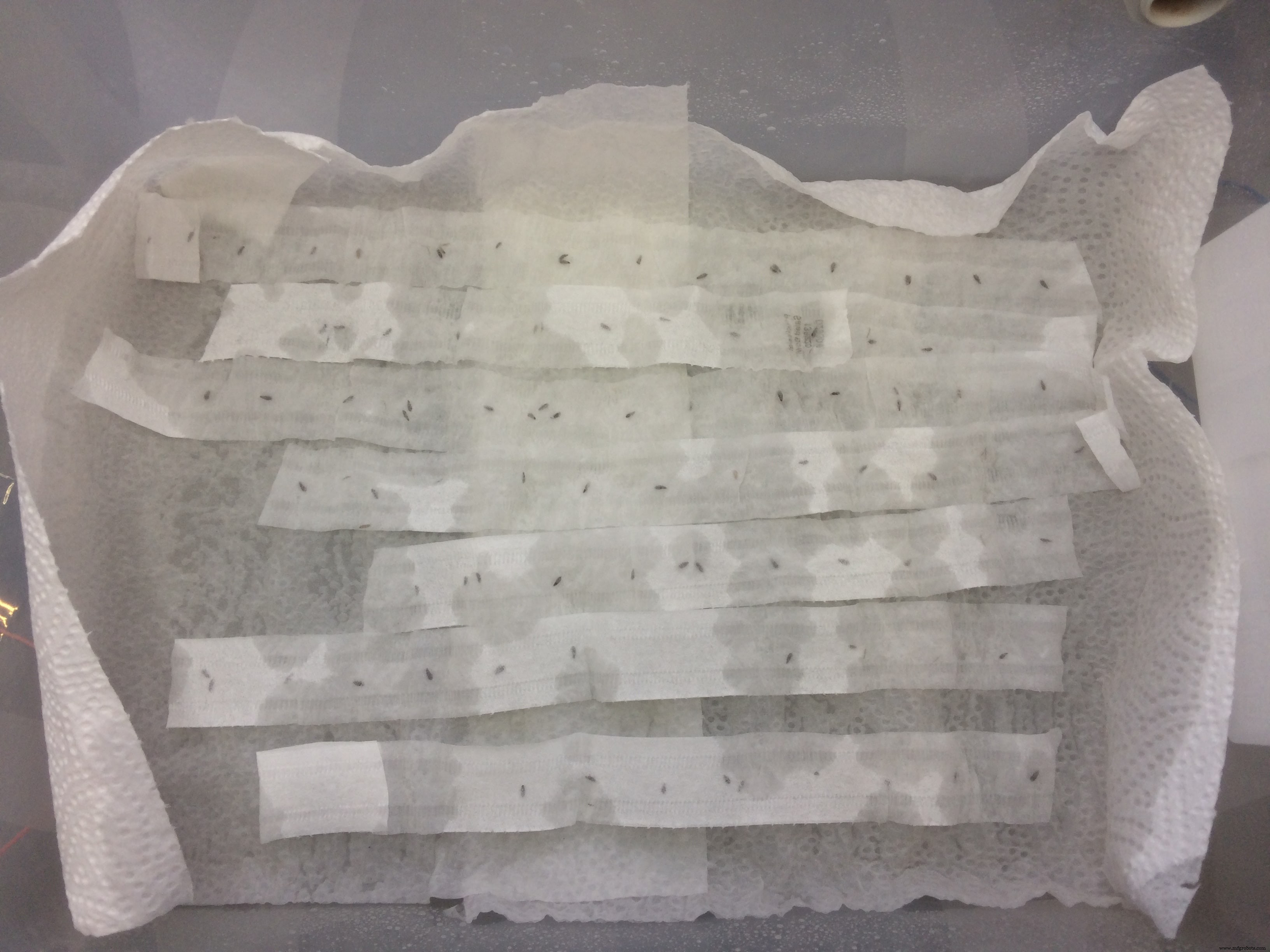
Saya meninggalkan benih selama 1,5 minggu, dan ketika saya membuka wadah, saya benar-benar terkejut!
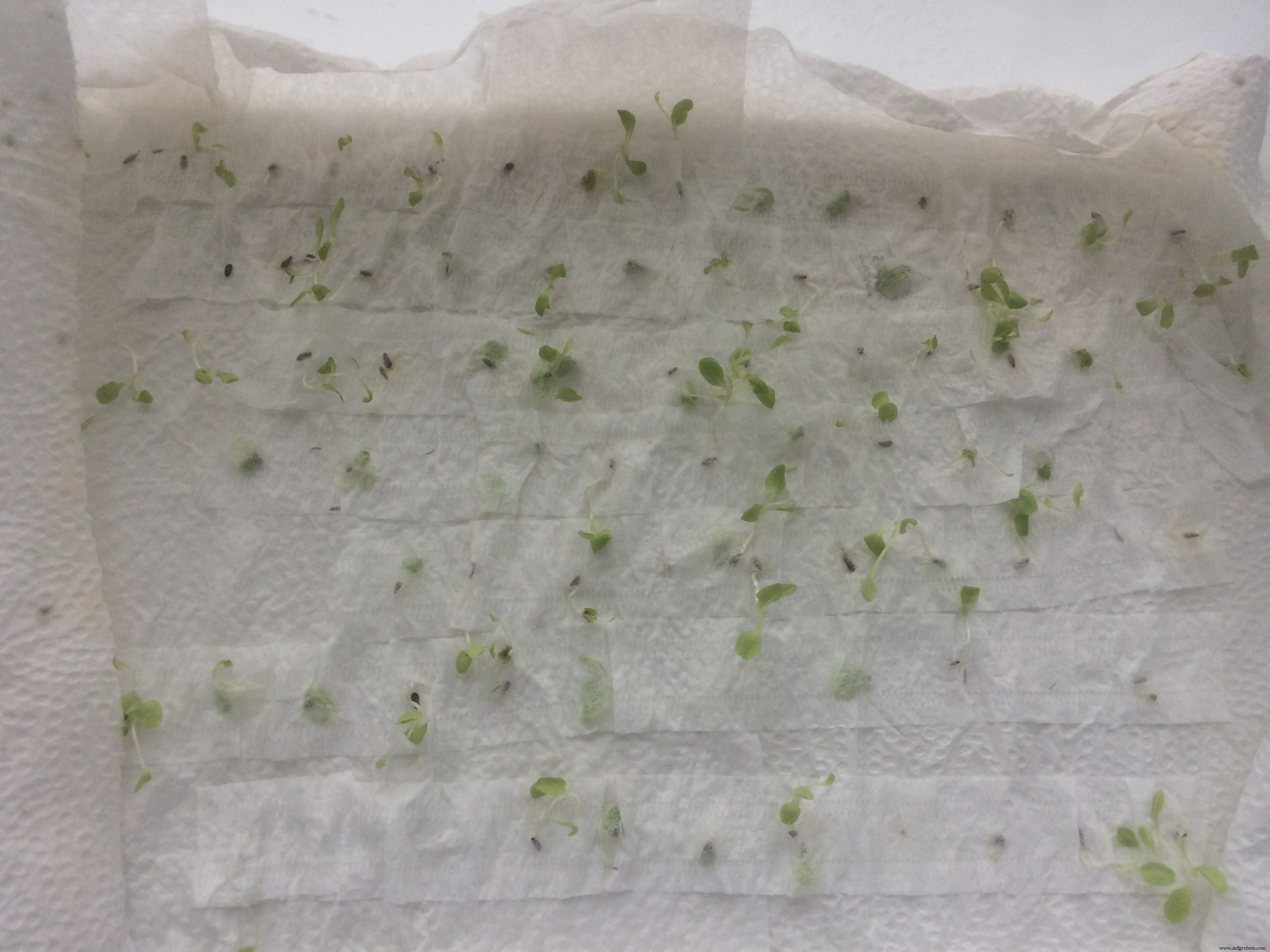
Hampir semua benih berkecambah! Saya senang seperti anak kecil)
Selanjutnya saya harus memilih tanaman kecil terbaik, yang memiliki batang paling tebal, dan hanya terlihat lebih besar dan lebih baik secara keseluruhan.
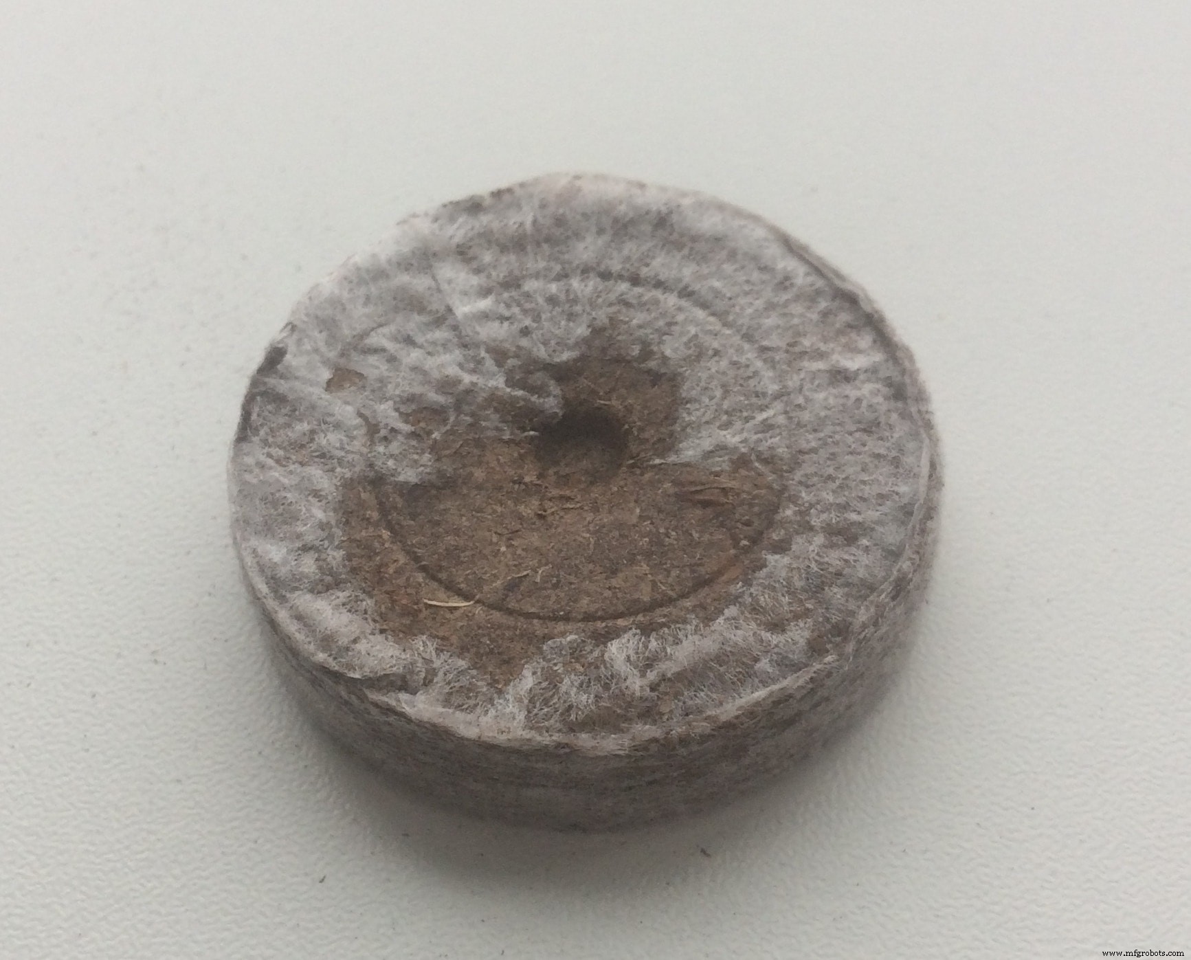
Dalam tutorial yang saya ikuti (YouTube blogger), orang tersebut merekomendasikan untuk menanam tanaman kecil ke media apa pun, sampai mereka memberi apa yang disebut "daun kedua". Di Amazon saya memesan pelet sabut kelapa . Mereka organik, memiliki sifat yang mirip dengan tanah, dan yang keren adalah ketika pelet disiram, ukurannya menjadi x6 kali lebih besar.
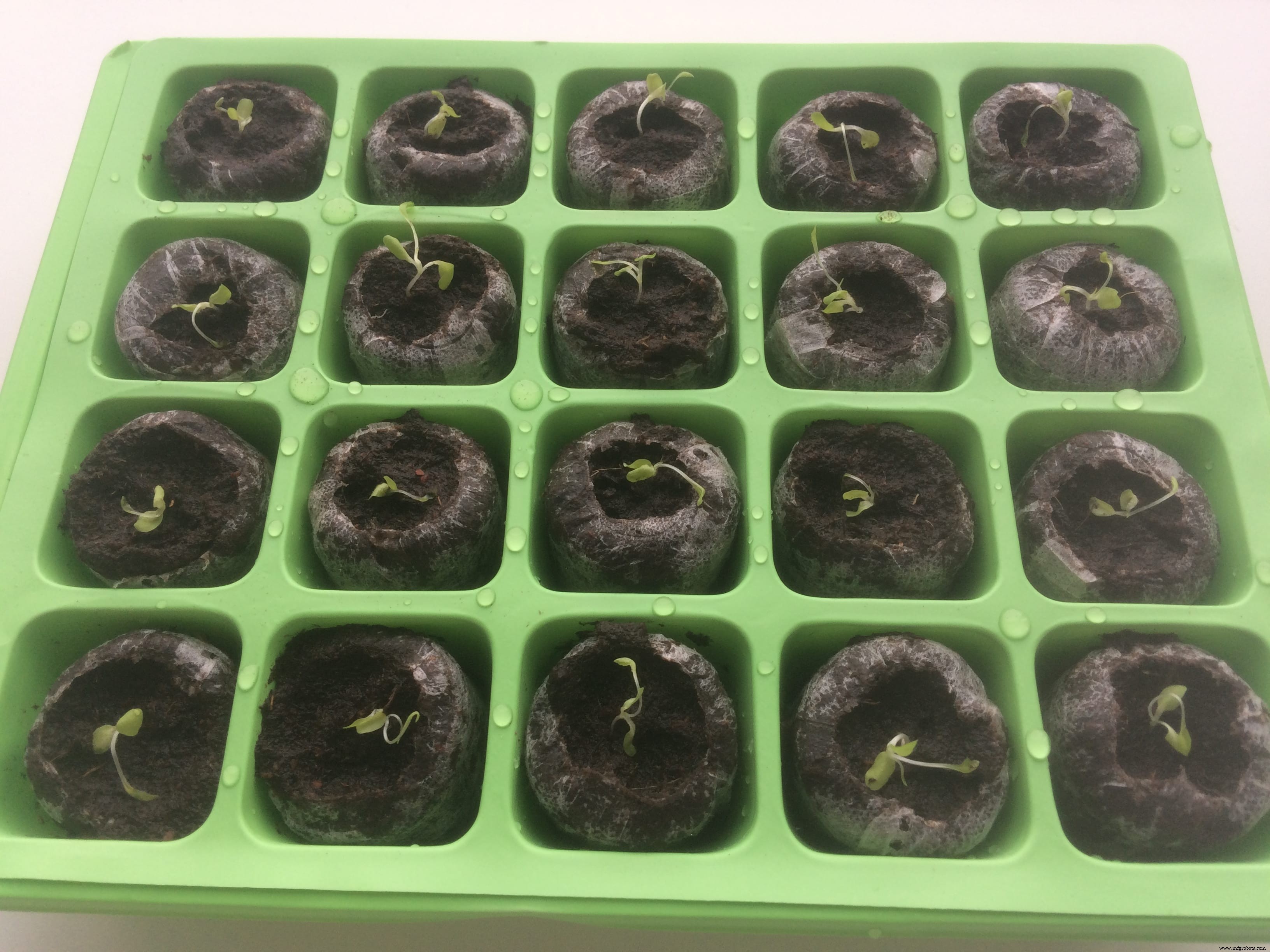
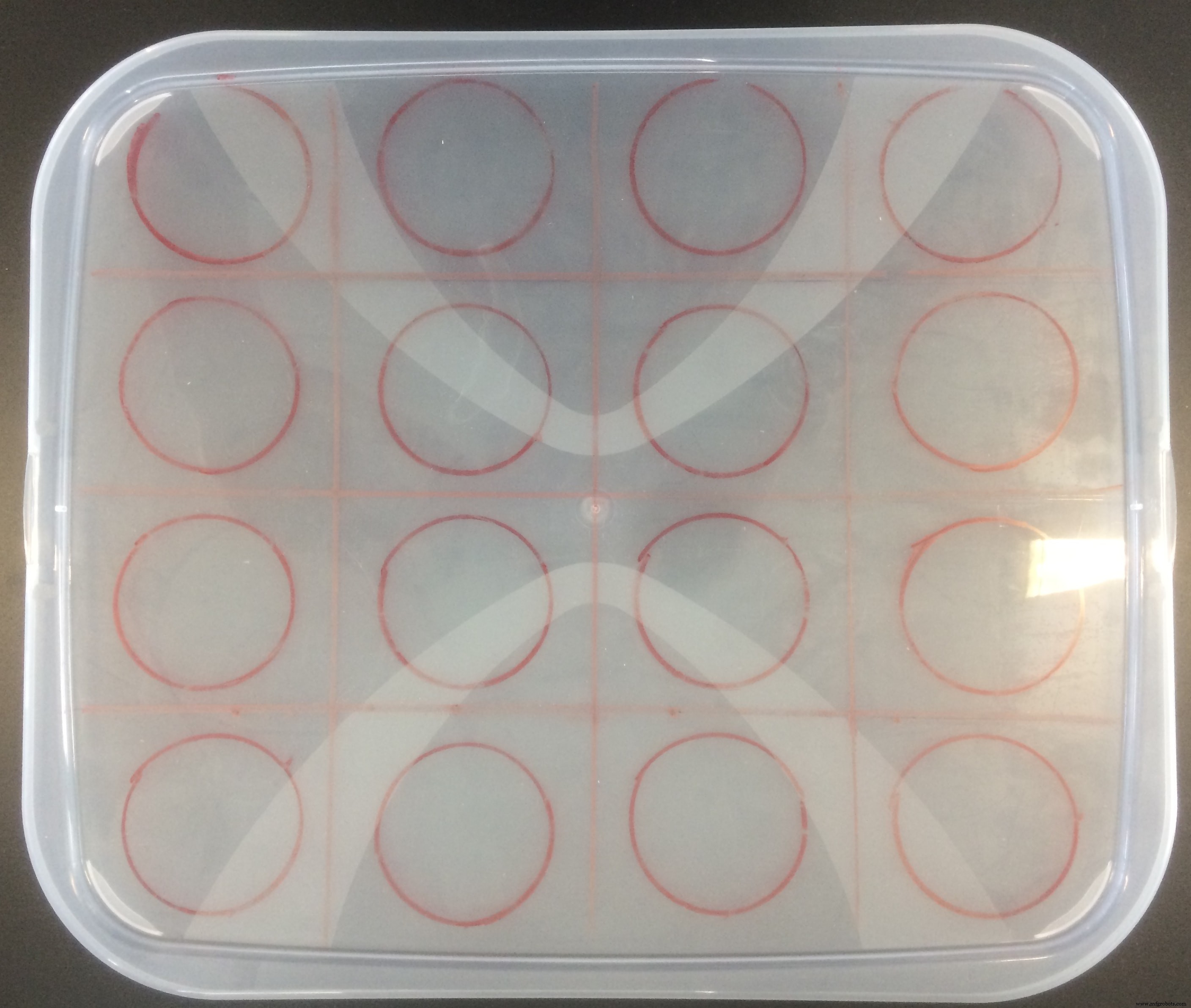
Saya juga membeli sebuah kotak, yang memiliki pemisah khusus untuk penanaman! Saya mendapatkannya hanya dengan 2 euro, dan ini membuat segalanya lebih teratur. Saya menempatkan pelet kelapa di dalam pemisah kotak, menyiramnya sampai benar-benar terhidrasi, meletakkan tanaman kecil di tengah, dan menutupi kotak dengan plastik transparan yang disertakan dengan kotak kit.
Rumah kaca kecil saya terlihat seperti ini:
Saya menutup kotaknya, dan meninggalkannya selama satu minggu!
Dan lagi ketika saya membukanya, saya terkejut! Mereka benar-benar menjadi lebih besar! Saya tidak pernah bisa membayangkan bahwa saya bisa menanam beberapa tanaman, saya hampir tidak bisa mengurus diri sendiri :D
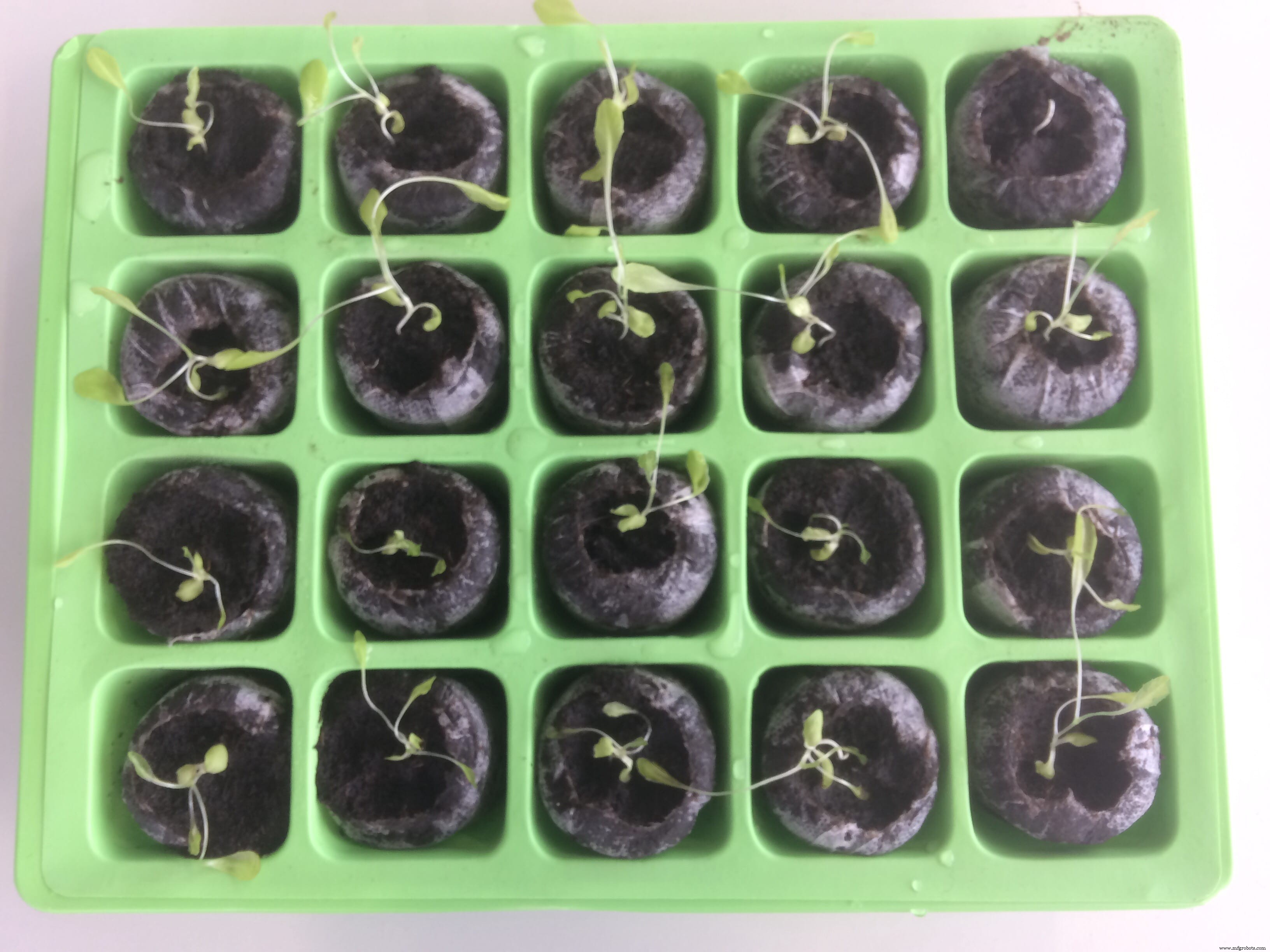
Setelah satu minggu, perbedaannya terlihat!
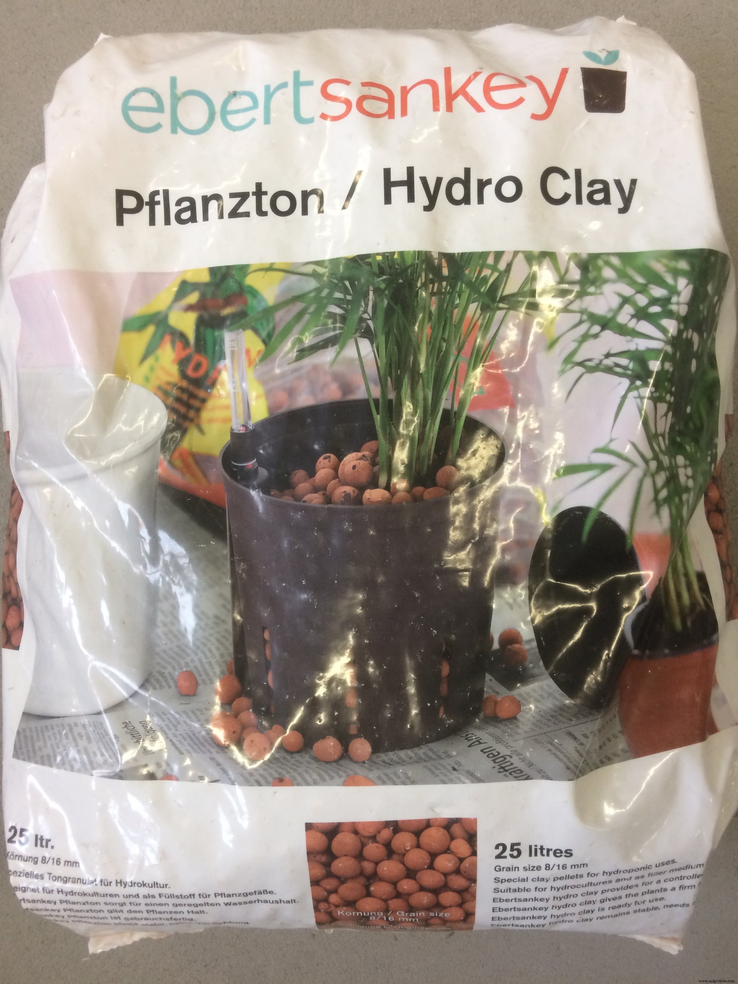
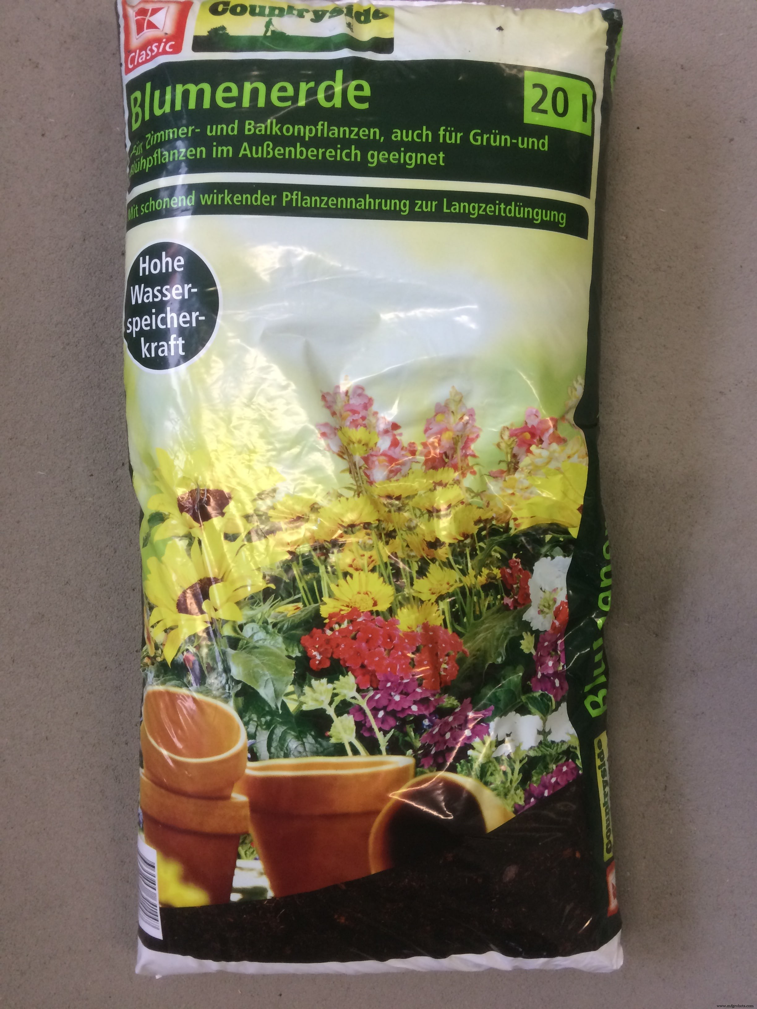
Sekarang ketika saya melihat akar pertama, saya dapat menempatkannya di tanah dan bola tanah liat, dan mulai bereksperimen dengan kabut!
Selama minggu Computer-Aided Design, saya mendesain cangkir jaring, yang saya gunakan untuk meletakkan tanaman
Saya juga membeli di toko lokal wadah plastik dengan ukuran perkiraan yang saya butuhkan, dan membuat sketsa lubang untuk dibor!
Dan inilah sistem pengujian saya, dengan tanaman di dalam pelet kelapa, dan bola tanah liat, serta tanah!
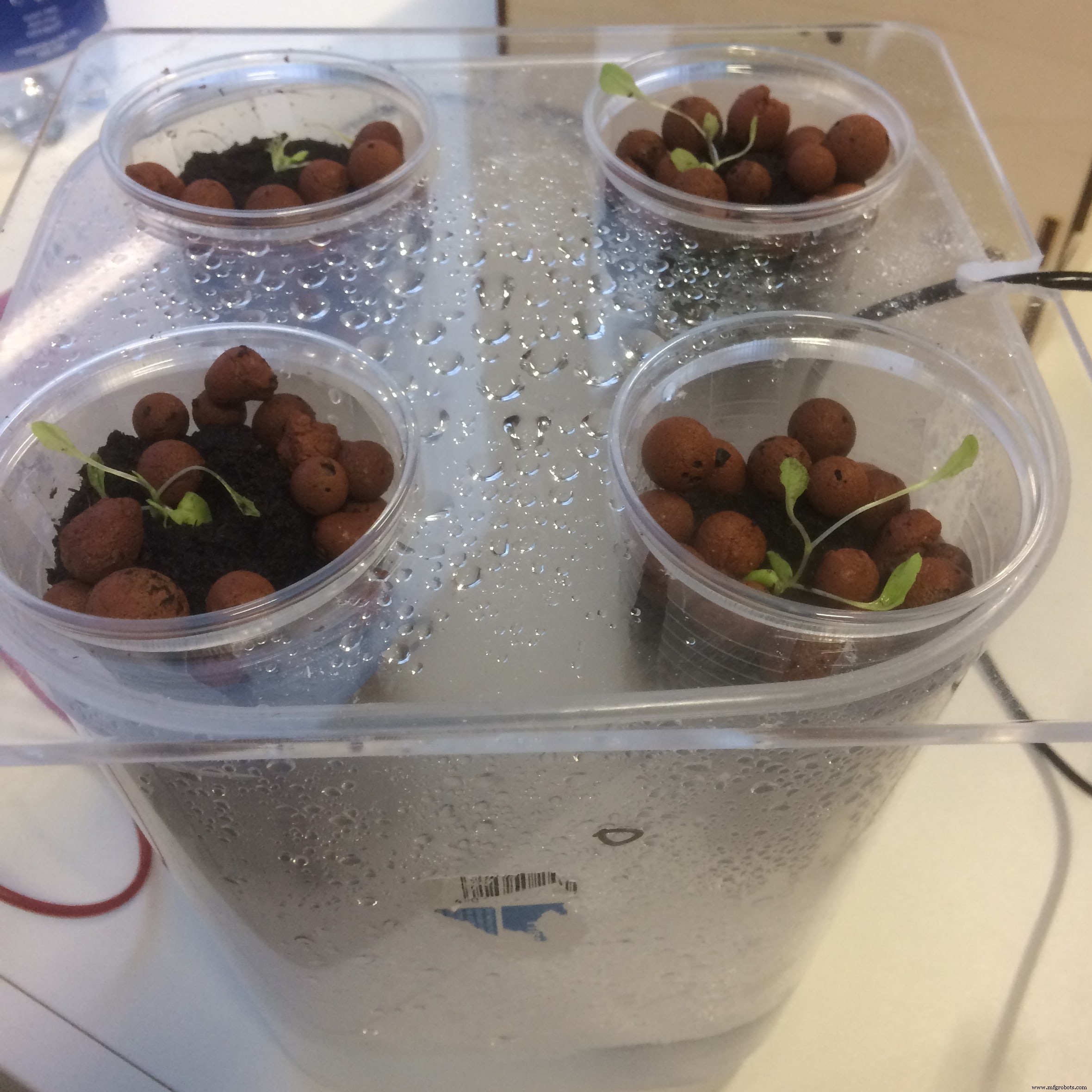
Sejujurnya, hasilnya bisa lebih baik :D
Hanya sedikit tanaman yang bertahan dalam sistem kabut saya. Dugaan saya adalah karena media tanamnya! Kabut tidak cukup kuat untuk membuat bola tanah liat tetap basah, begitu juga dengan tanah.
Liburan Paskah!
Selama liburan Paskah saya tidak melakukan apa-apa, dan karena lab ditutup, semua sistem juga mati. Jadi tanaman saya mati semua
Dengan pikiran yang segar, saya memutuskan untuk membuat sistem lain, tetapi kali ini menggunakan media tanam lain berdasarkan pengamatan sebelumnya
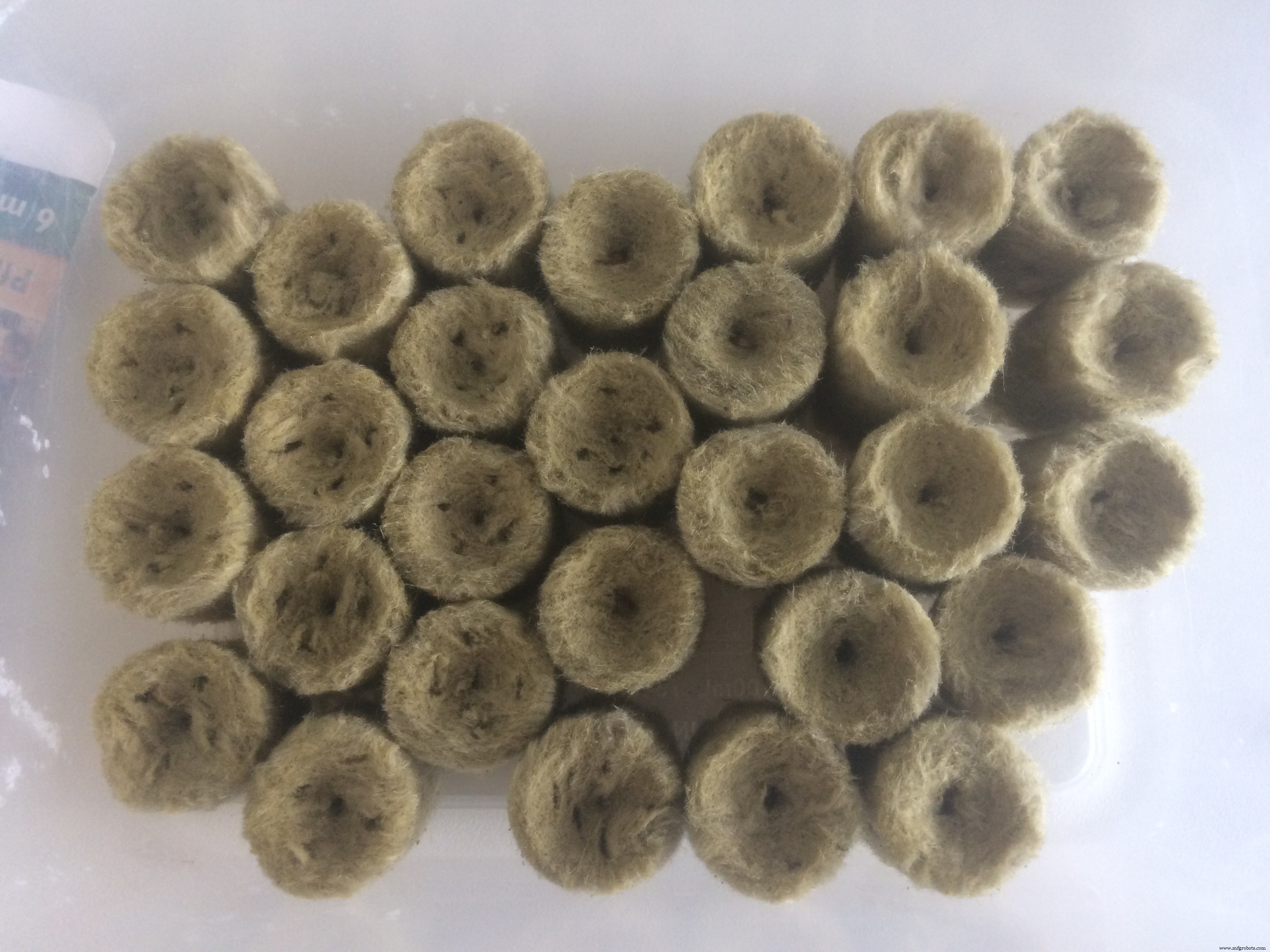
Media tanam yang saya pilih untuk sistem ini adalah Rock Wool . Saya membelinya di toko IKEA lokal kami. Saya juga membeli beberapa benih dari departemen mereka

Dan saya menempatkan benih baru ke wol batu untuk berkecambah selama satu minggu!
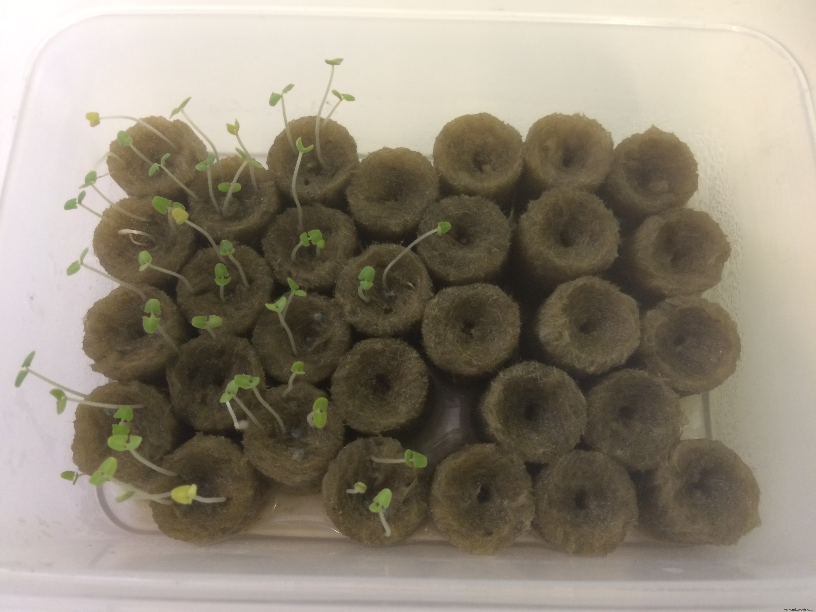
Setelah satu minggu saya memeriksa kotak saya, dan melihat bahwa satu jenis benih berhasil, yang lain gagal! Karena kurangnya waktu, saya melanjutkan dengan benih yang berkecambah
Sementara itu, saya menyiapkan sistem kabut lain, dan akan mencoba meningkatkan waktu kerjanya, untuk melihat apakah saya bisa berkecambah benih menggunakan kabut, HANYA KABUT!
Saya akan terus bereksperimen dengan parameter dan pengaturan yang berbeda, dan melihat seberapa jauh saya dapat mencapai!)
Desain &Produksi Elektronik
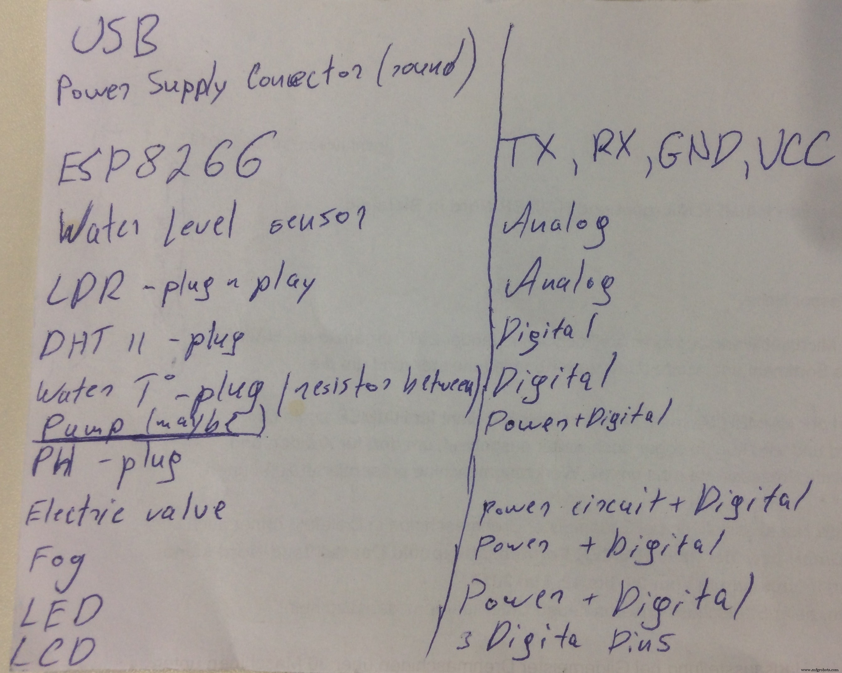
Sebelum mulai mendesain papan akhir, saya duduk untuk menggambar di selembar kertas semua fitur dan persyaratan yang harus diterapkan dan dipenuhi oleh papan! Saya juga melacak berapa banyak pin yang akan digunakan, untuk memperkirakan lebih baik dan memutuskan mana yang akan menjadi mikroprosesor akhir
Berikut adalah sketsa apa yang harus ada di papan tulis:
Pilihan terakhir di papan mana yang akan digunakan adalah antara satshakit dari Daniele Ingrassia dan FABLEO oleh Jonathan Grinham
satshakit adalah 100% Arduino IDE dan library yang kompatibel, fabbable dan open source board, dan juga versi Fabkit yang ditingkatkan.
Peningkatan dan fitur utama dari Fabkit adalah:
- lebih murah (7-9 euro vs 13 euro)
- 100% kompatibel dengan IDE Arduino default (satshakit dikenali sebagai Arduino UNO)
- ADC6/7 terhubung bukannya ADC6/7 tidak terhubung (laser satshakit dan cnc)
- ruang yang lebih besar untuk menyolder dengan mudah (laser satshakit dan cnc)
Di sisi lain, FabLeo memiliki fitur yang sangat mirip, ditambah perangkat keras USB! Karena saya sudah menggunakan ATmega328p sebelumnya, saya ingin mencoba sesuatu yang baru, dan memutuskan untuk menggunakan desain FabLeo sebagai titik awal saya
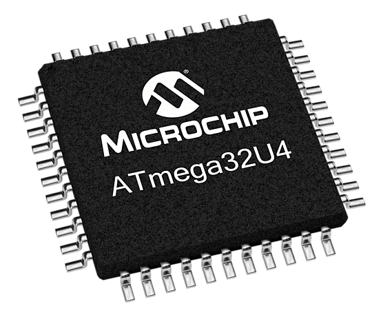
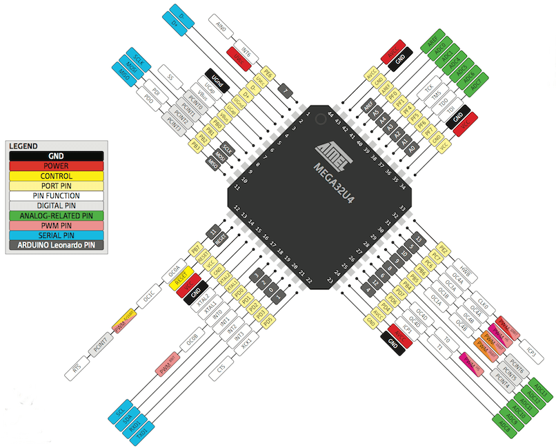
Alkitab My saya dan panduan #1 untuk tugas ini adalah pinout ATmega32u4
Untuk mendesain papan, perangkat lunak yang akan saya gunakan untuk ini adalah EAGLE (Easily Applicable Graphical Layout Editor) adalah tangkapan skema EDA yang fleksibel dan dapat diperluas, tata letak PCB, autorouter, dan program CAM. EAGLE populer di kalangan penggemar karena lisensi freeware dan ketersediaan perpustakaan komponen yang kaya di web.
Eagle memiliki dua jendela yang digunakan secara bersamaan untuk mendesain papan:
- Skematis (.sch) - komponen logika
- Tata Letak Papan (.brd) untuk papan sebenarnya yang kami giling
Setelah saya menginstal EAGLE, hal pertama yang ingin saya lakukan adalah Buat Skema Baru . Skema dalam elektronika adalah gambar yang mewakili rangkaian. Ini menggunakan simbol untuk mewakili komponen elektronik dunia nyata. Simbol paling dasar adalah konduktor sederhana (jejak), ditampilkan hanya sebagai garis. Jika kabel terhubung dalam diagram, mereka ditunjukkan dengan titik di persimpangan.
Untuk menempatkan komponen saya pada skema, saya harus mengunduh dan menggunakan Perpustakaan special khusus . Eagle memiliki banyak perpustakaan komponen bawaan yang dapat kita gunakan. Jaringan fab juga memelihara perpustakaan yang terus diperbarui:
fab.lbr
Untuk menginstal perpustakaan, di lingkungan EAGLE, buka bilah alat atas dan pilih Perpustakaan Tidak bisa. Kemudian pilih gunakan dan buka .lbr file yang baru saja saya unduh.
Sekarang saya bisa pergi ke Add component dan memilih perpustakaan, saya memilih komponen yang ingin saya tempatkan.
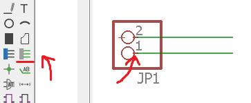
Ketika saya memiliki semua komponen yang ditempatkan pada skema saya, saya harus menghubungkan masing-masing ke pin mikroprosesor. Di menu sebelah kiri EAGLE, saya klik Net , perintah yang memungkinkan saya menggambar garis hijau dan menghubungkan pin. Yang penting adalah memulai koneksi dari garis kecil pada pin (saya menandainya pada gambar)
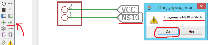
Untuk menghindari banyak koneksi, saya akan menggunakan Label. . Di menu sebelah kiri EAGLE, saya tekan Add Label dan menambahkannya ke akhir jalur koneksi saya. Jika saya menekan klik kanan lalu pilih nama , saya dapat menghubungkan label dengan nama yang sama yang saya gunakan untuk pin mikroprosesor, dan menghubungkannya dengan cara ini!
Jika saya melakukan semuanya dengan benar, sebuah pesan akan muncul yang menyatakan:Apakah Anda yakin ingin menghubungkan label Anda (N$10) dengan GND?
Pada tahap ini, dalam kimia, yang penting adalah Logika dari semua koneksi, bukan seperti yang terlihat. Setelah saya selesai menempatkan semua komponen, dan menghubungkannya secara logis, beginilah tampilannya:
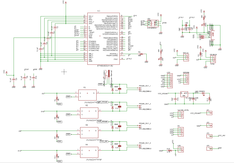
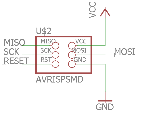
Saya menambahkan AVRISP kepala peniti, dan menempatkannya sesuai urutan konektor. Pin ini akan digunakan untuk memprogram papan saya.
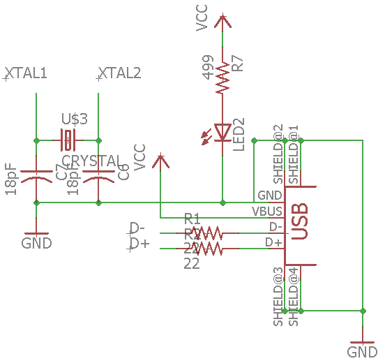
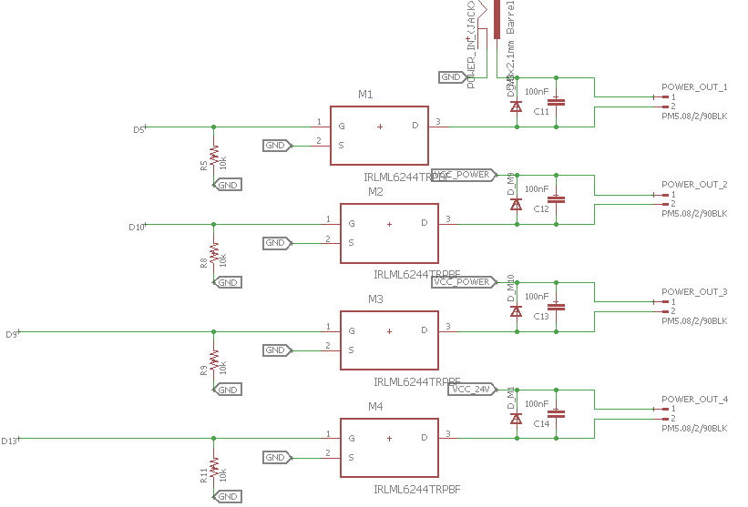
Berikut adalah skema USB sirkuit bersama dengan kristal
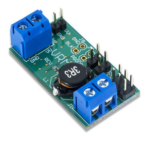
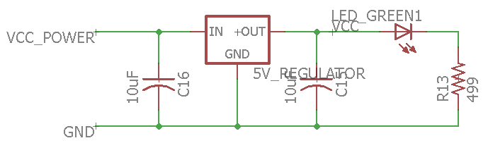
Saya juga menambahkan Pengatur Tegangan sirkuit yang akan memberi daya pada seluruh papan dengan mengubah input 12V menjadi 5V
Salah satu fitur penting dari papan ini adalah MOSFET sirkuit, saya menambahkan 4 di antaranya, 3 terhubung langsung ke input (12V), dan satu akan terhubung ke regulator tegangan step-up. Yang terakhir akan digunakan untuk menyalakan kabut yang bekerja pada 24V
Setelah saya mengecek kembali semua koneksi, saya bisa melanjutkan ke langkah berikutnya, yaitu Board Layout . Di menu atas, saya tekan Generate/Switch to Board .
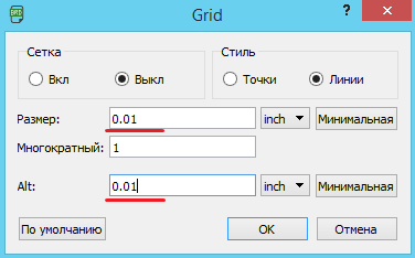
Hal pertama yang saya lakukan adalah meningkatkan Grid resolusi. Saya pergi ke View menu, dan tekan Grid , dan ubah nilainya menjadi 0.01 . Ini akan membuat saya lebih tepat saat menggambar garis rute.
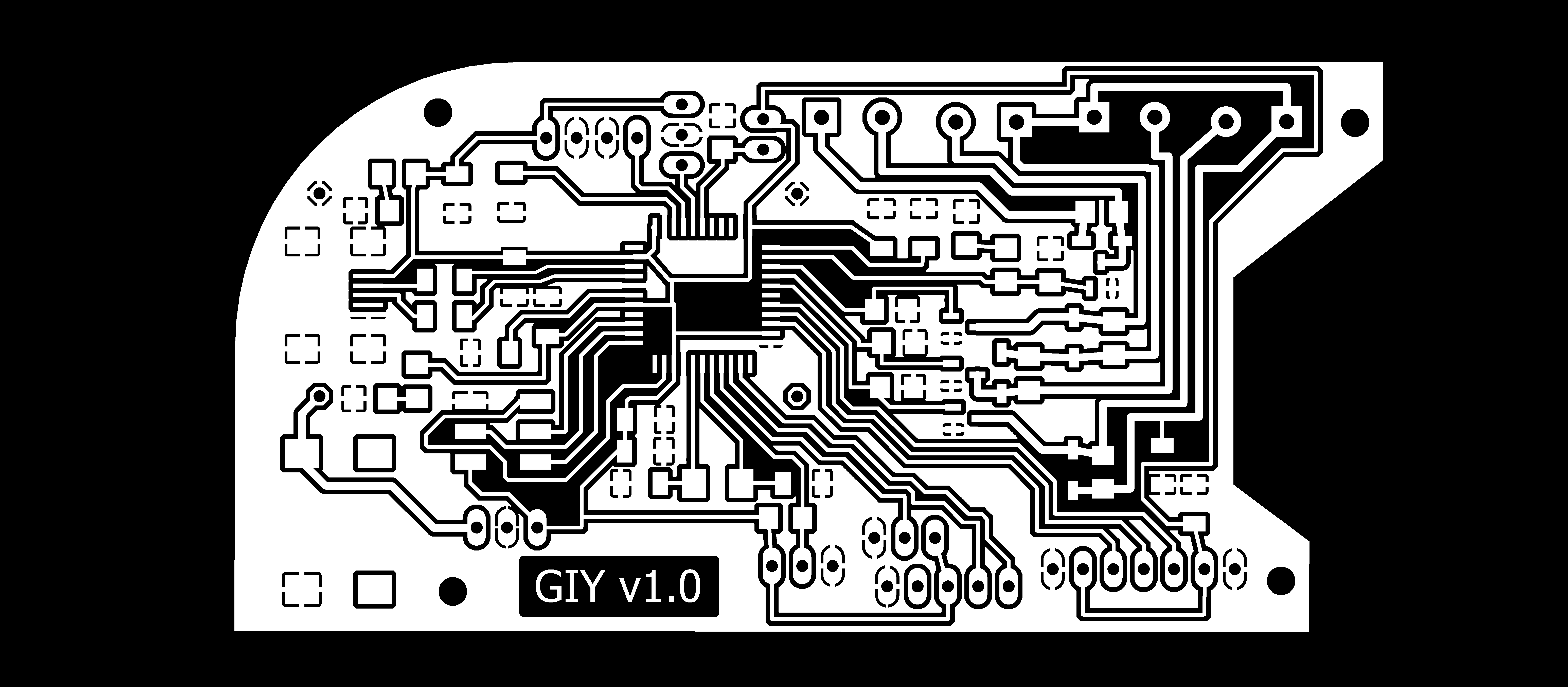
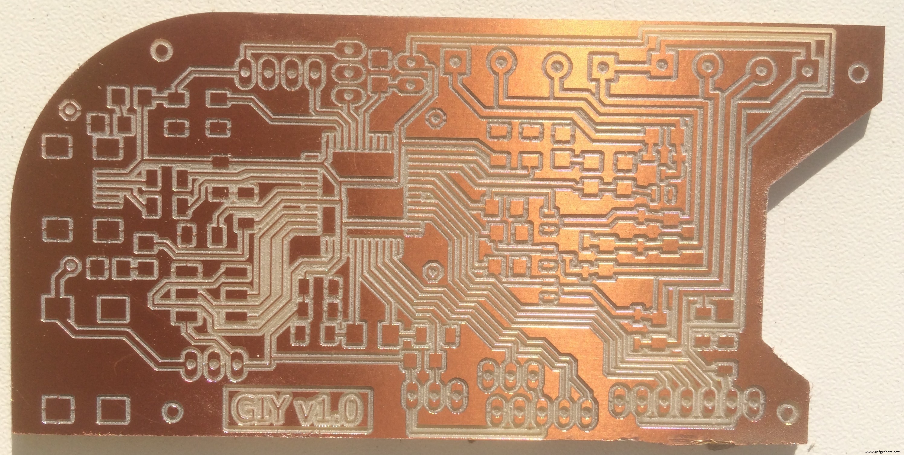
Anehnya, perutean papan paling kompleks yang saya buat sejauh ini juga yang tercepat!) Saya bangga pada diri saya sendiri. Pengalaman membuat papan memiliki pengaruh yang baik dalam meningkatkan kecepatan. Setelah saya selesai melakukan routing, beginilah penampakan binatang kecil itu:
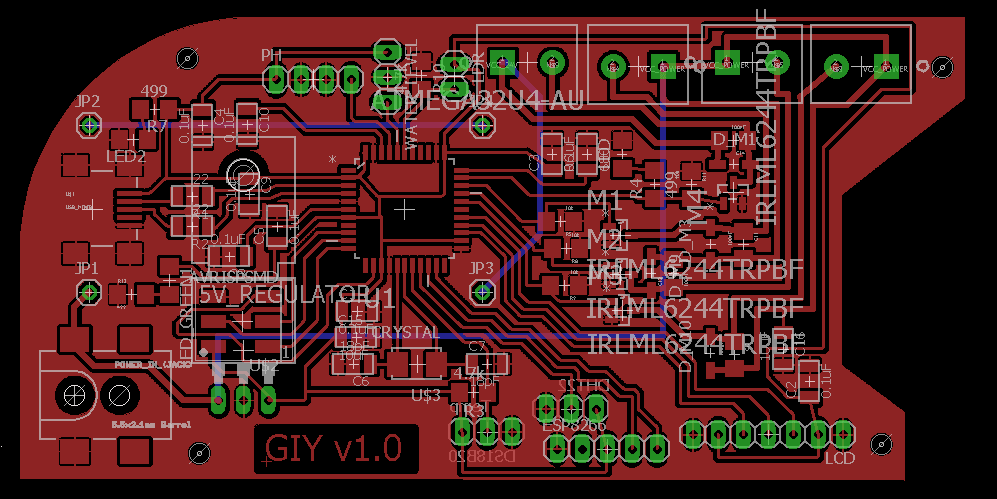
Untuk papan ini saya juga menggunakan trik yang saya pelajari sebelumnya. Saya menggambar poligon di sekitar komponen saya, dan dengan menekan klik kanan pada garis poligon, saya mengubah nama menjadi GND. Ini akan mengisi seluruh area di dalam poligon, dan membuatnya menjadi GND.
Ini akan menghemat banyak waktu, ruang, dan tenaga
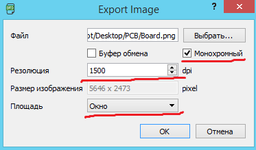
Saat saya memeriksa ulang semuanya, saya dapat Ekspor file saya sebagai .png gambar.
Di jendela yang muncul, saya meningkatkan resolusi menjadi 1500 dpi , klik monokrom , dan pilih window modus.
Untuk mengedit gambar .png, saya akan menggunakan saya membuka gambar saya di GIMP , dan menggunakan alat pilih persegi panjang , saya memilih gambar dengan menyisakan ruang dari semua sisi. Setelah saya tekan File dan Salin daerah yang dipilih. Untuk melanjutkan bekerja dengan gambar yang dipilih, saya klik lagi pada File , dan Buat dari Clipboard
Inilah yang saya dapatkan setelah semua pengeditan:
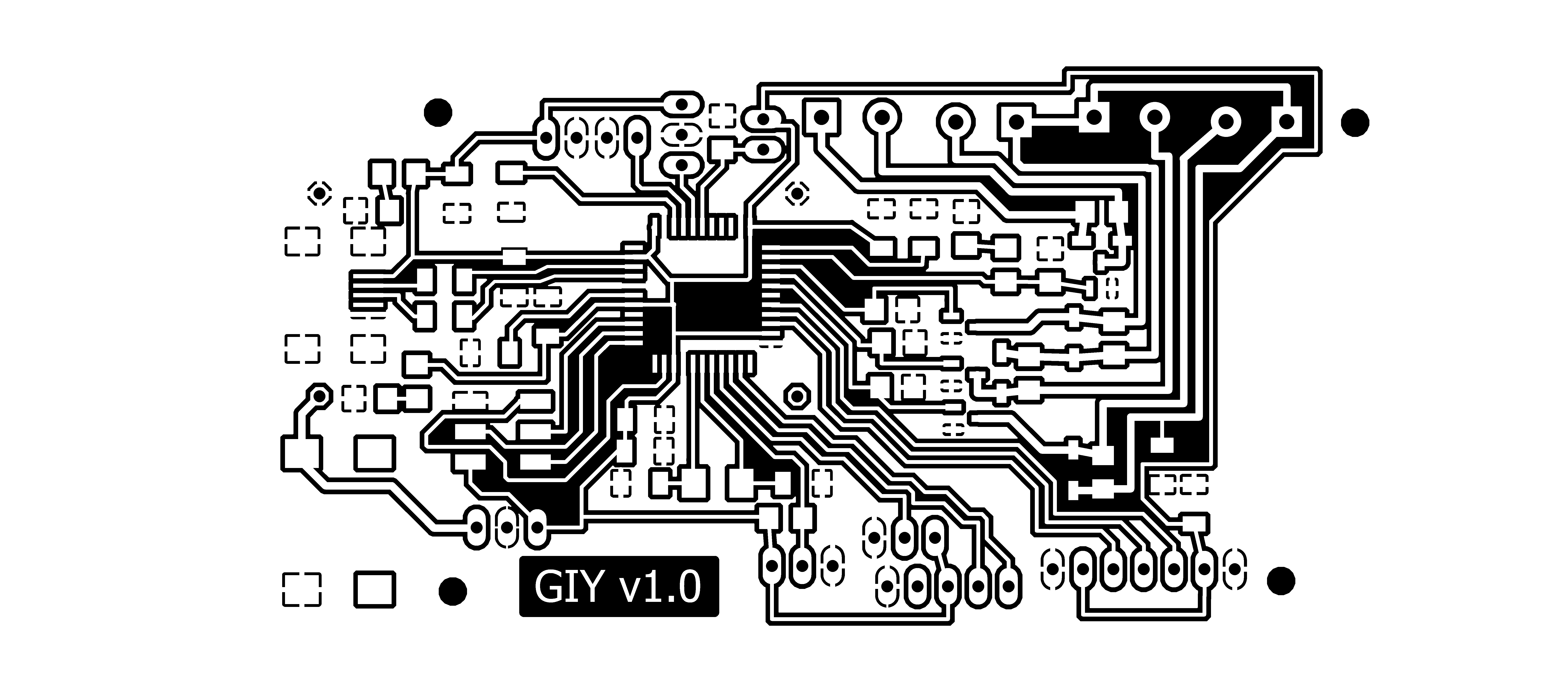
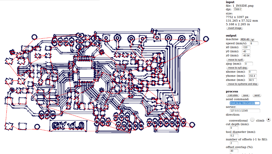
Gambar ini siap dicetak, dan saya akan menyebutnya Inside_Cut
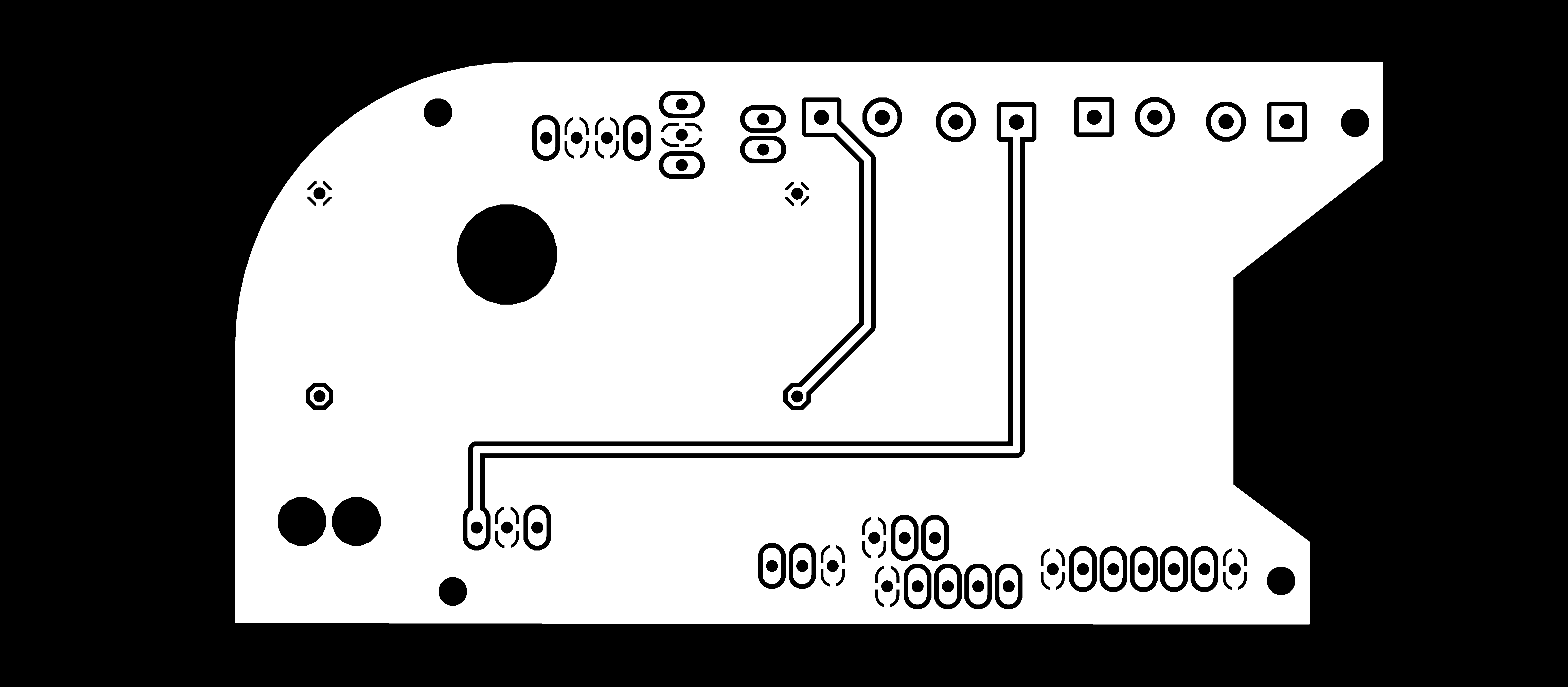
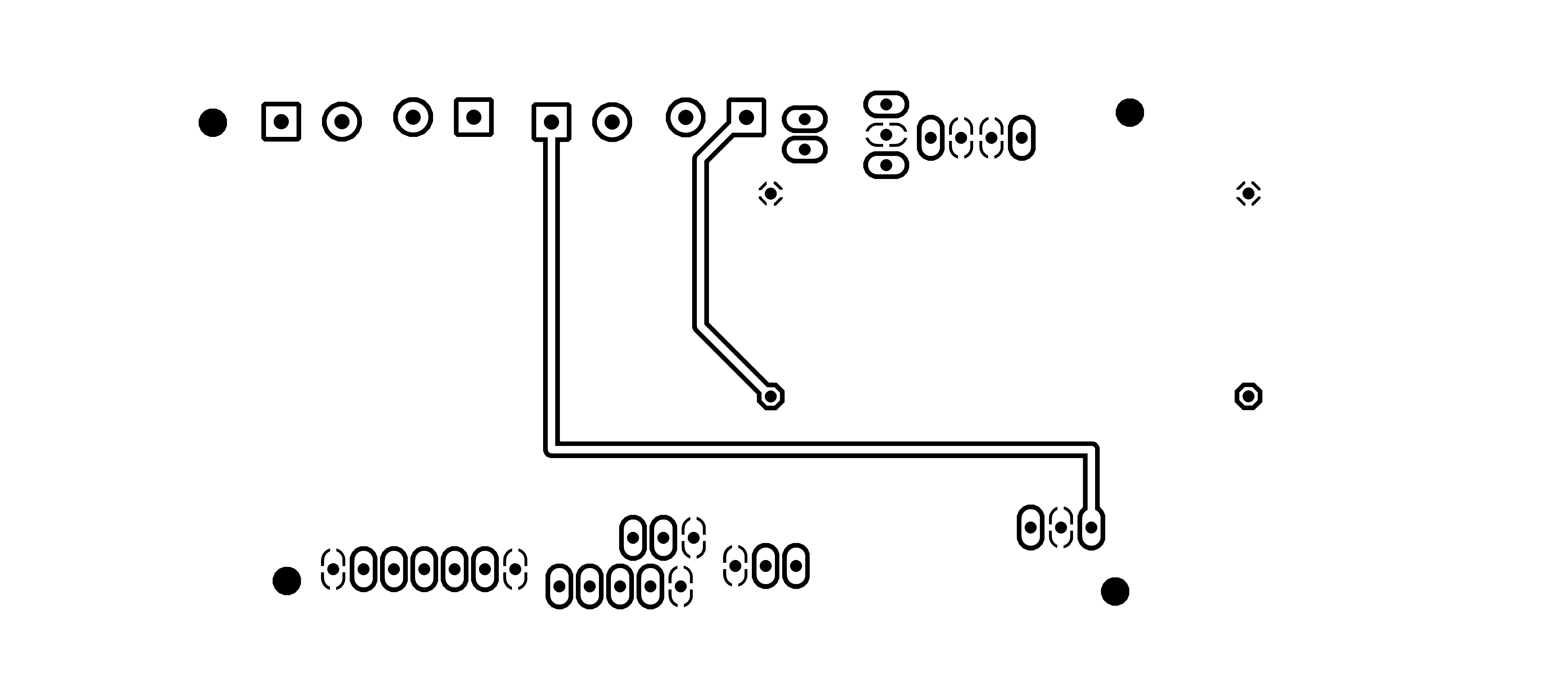
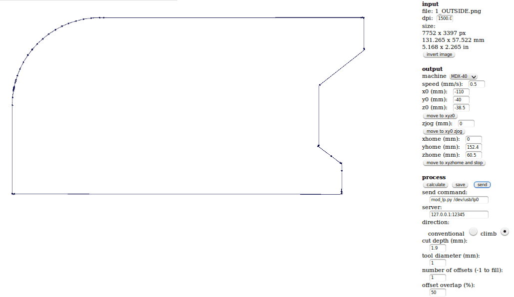
Saya mempersiapkan proses untuk Outside Cut , dan inilah yang saya dapatkan:

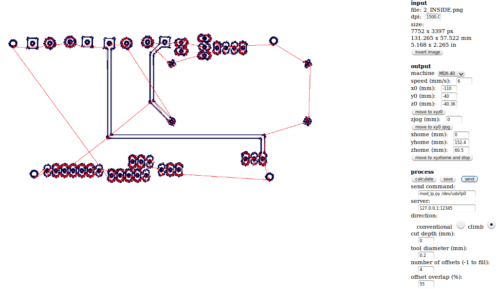
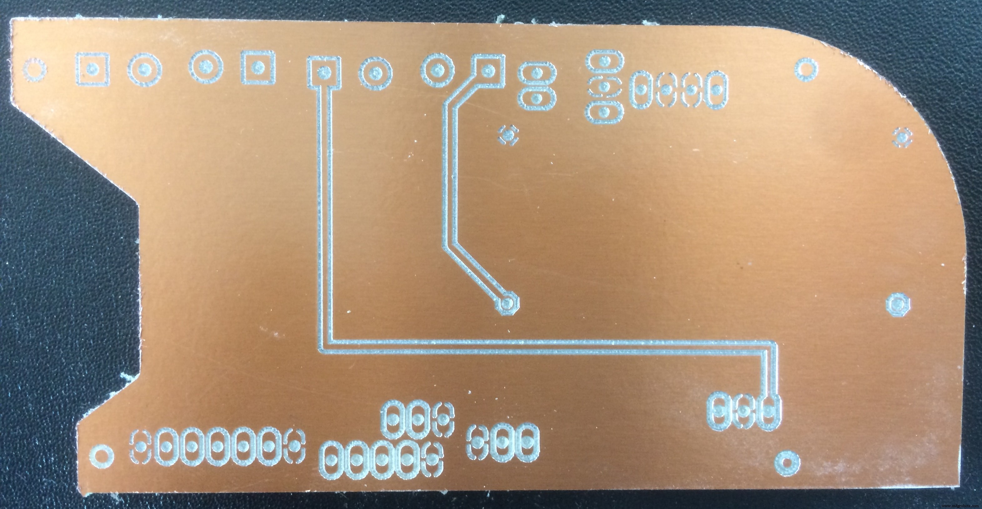
Karena papan saya bersisi dua, saya harus menggiling dua bagian, lalu merekatkannya. Satu-satunya hal yang perlu diingat adalah bahwa bagian bawah, harus dicerminkan secara horizontal
Bagian bawah Inside_Cut

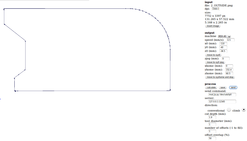
Bagian bawah Outside_Cut
Sekarang saya dapat melanjutkan ke mesin penggilingan CNC. Jadi, sekali lagi saya menggunakan FabModules untuk mengonversi file .PNG menjadi Gcodes untuk mesin Roland.
Mari mulai bekerja dengan Modul Fab. Saat saya memasukkan alamat ip ke jendela browser, antarmuka pertama yang akan muncul adalah:

Setelah saya menekan tombol abu-abu format input , menu baru akan muncul dengan opsi untuk memuat gambar .PNG. Di sini saya mengunggah gambar pertama, yang merupakan ukiran bagian dalam. Setelah melakukan itu, pratinjau gambar akan muncul di Modul Fab dan juga bidang lain dan parameter lainnya akan muncul
Di sisi kanan jendela, kami memiliki banyak parameter input. Untuk dapat menggerakkan mesin, kita harus memasukkan parameter berikut:
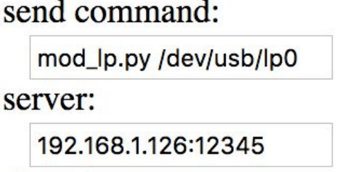
mod_lp.py /dev/usb/lp0 ke dalam perintah kirim bidang
hostname_of_your_machine ke server field (hanya alamat tanpa http atau /)
Untuk memindahkan mesin, saya cukup memasukkan koordinat posisi x, y, dan z di bidang masing-masing. Sebelum memindahkan mesin saya harus memastikan bahwa zjog parameter selalu diatur ke 0, bahkan jika itu akan berubah secara otomatis. Untuk memindahkan mesin saya harus menekan tombol move to xyz0 tombol.
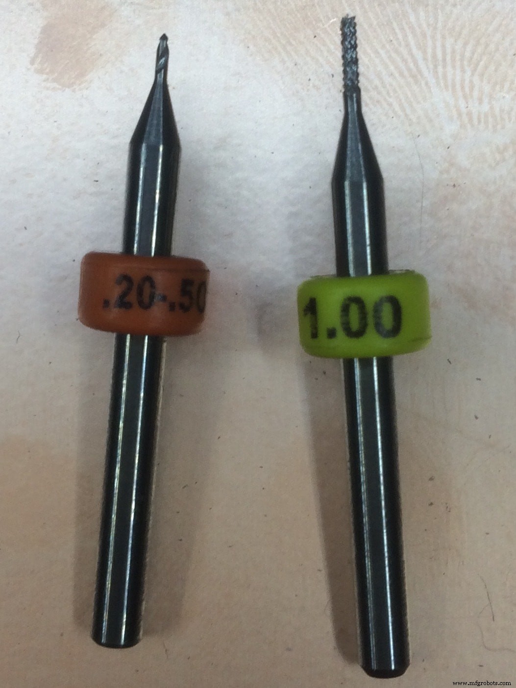
* Sebuah peretasan kehidupan kecil adalah dengan menggunakan multimeter dan memeriksa apakah ada hubungan antara alat dan permukaan. Sebagai alat untuk mengukir PCB disarankan menggunakan diameter 0.2 mm dan dibawahnya, sedangkan untuk pemotongan kita bisa menggunakan 1 mm alat.
Jadi pengaturan akhir saya terlihat seperti ini:
Untuk outer cut settingnya tetap sama dengan pengecualian nilai Z-Axis, karena saya mengganti tool 0.2mm dengan tool 1mm. Begini tampilannya:
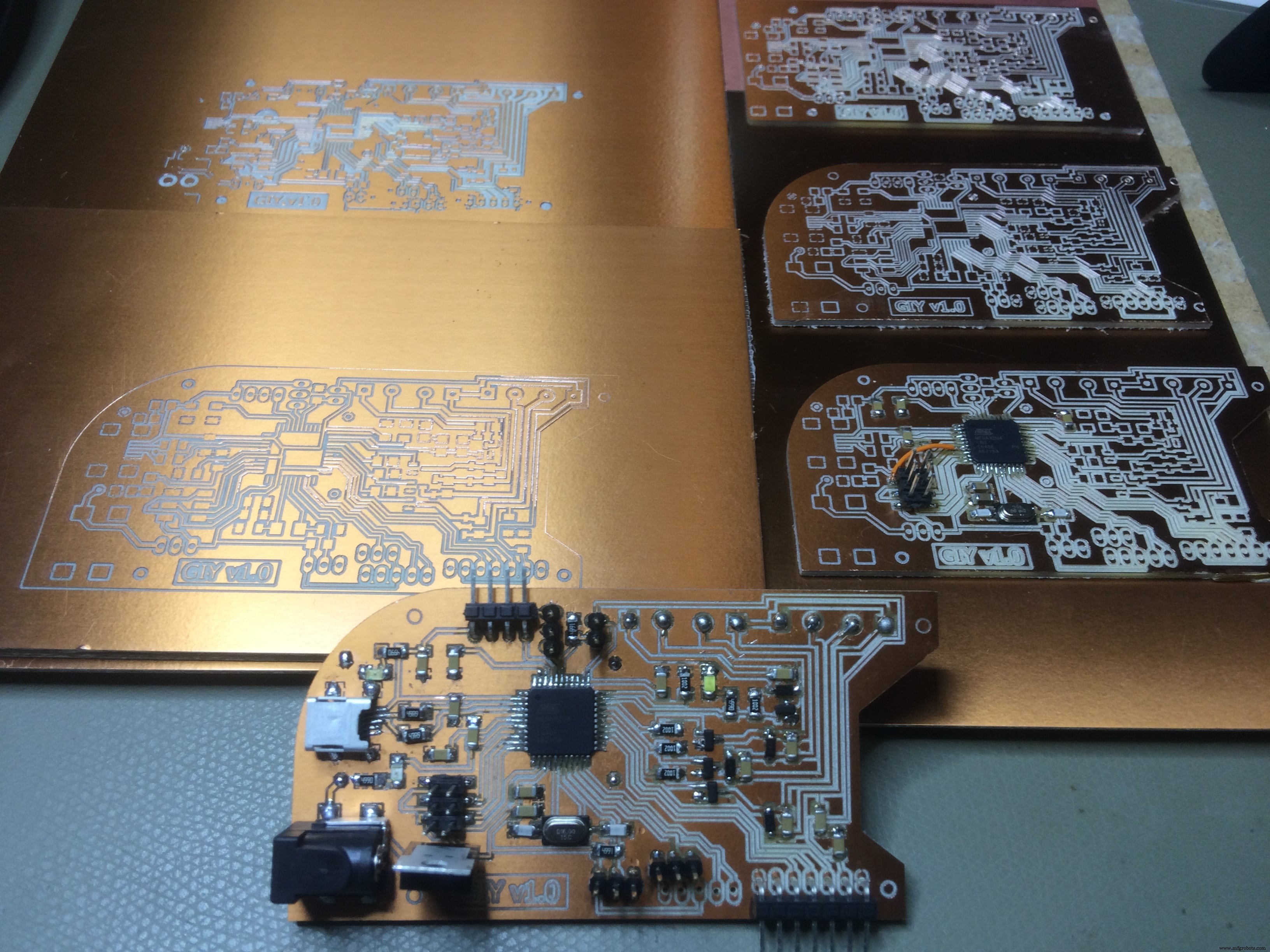
Ulangi proses yang sama untuk Bagian bawah dan giling bagian Dalam dan Luar:
Ini adalah hasil akhir untuk Atas bagian:
Dan bagian Bawah bagian:
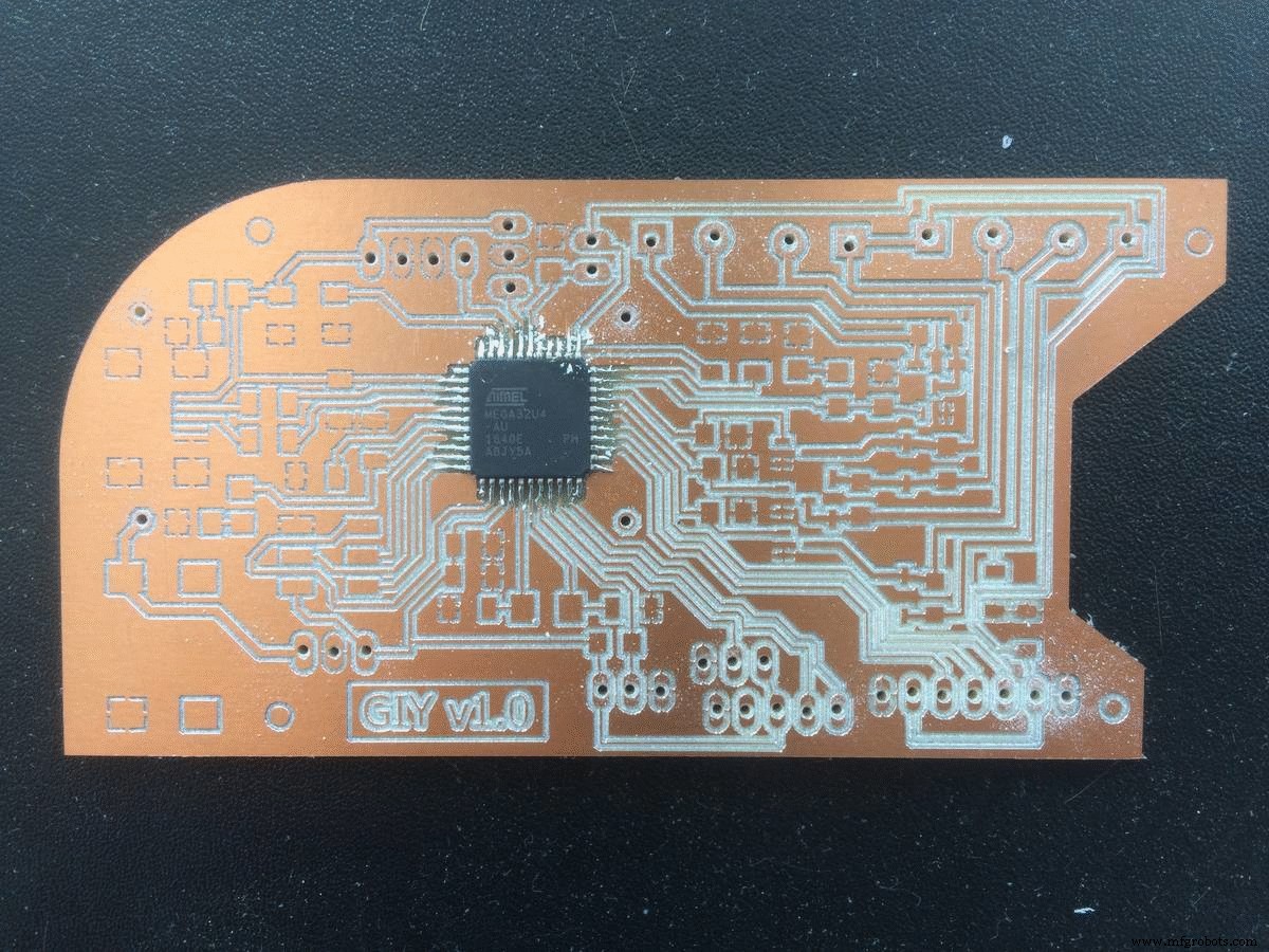
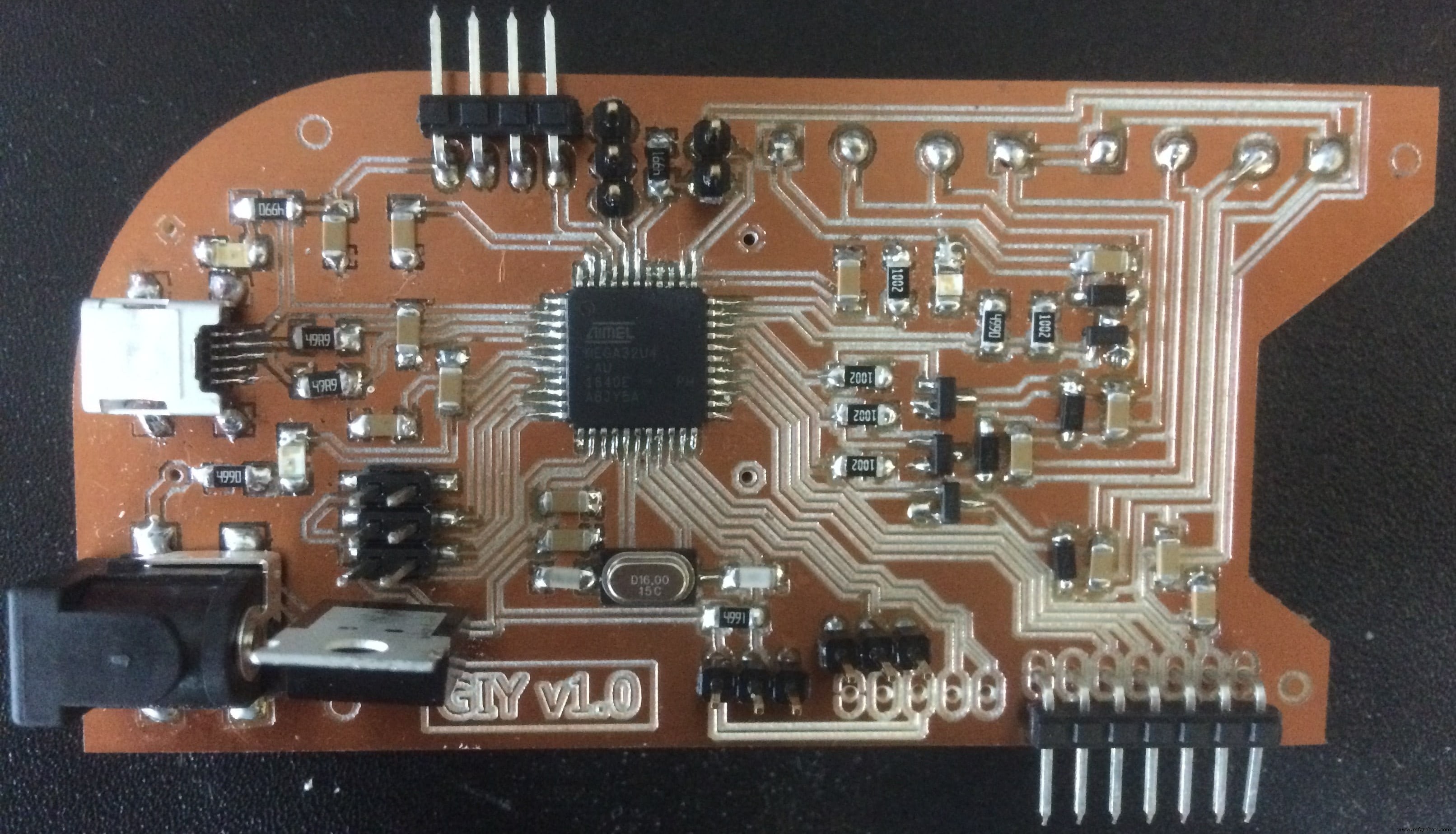
And now Let's solder this!
In order to make sure that I soldered everything in a right way, after each component soldered, I used the multimeter to check if there is conductivity between the component and the traces.
Short animation of the process:
When I plugged in the PCB board to check if everything is fine, I noticed an error. From experience, I know that the error was from a short circuit, because the computer was disconecting the Arduino all the time I connect the VCC and GND to it. So my guess was that somewhere on the board VCC and GND are connected, and using the multimeter, I confirmed that I was right.
It was late, and I got so f*ckin' mad because of that, took me one hour under the microscope to find that little mistake. Here it is:
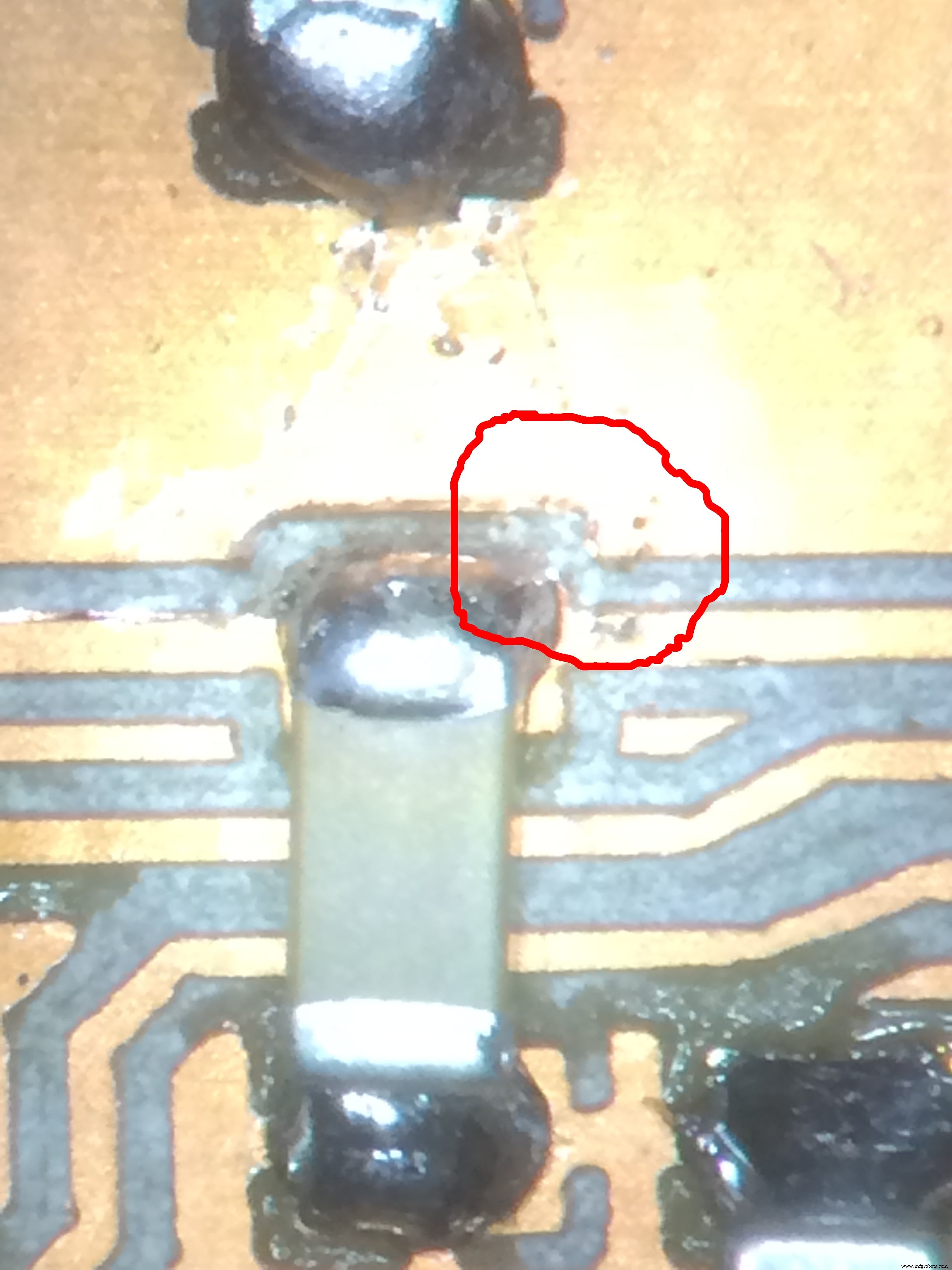
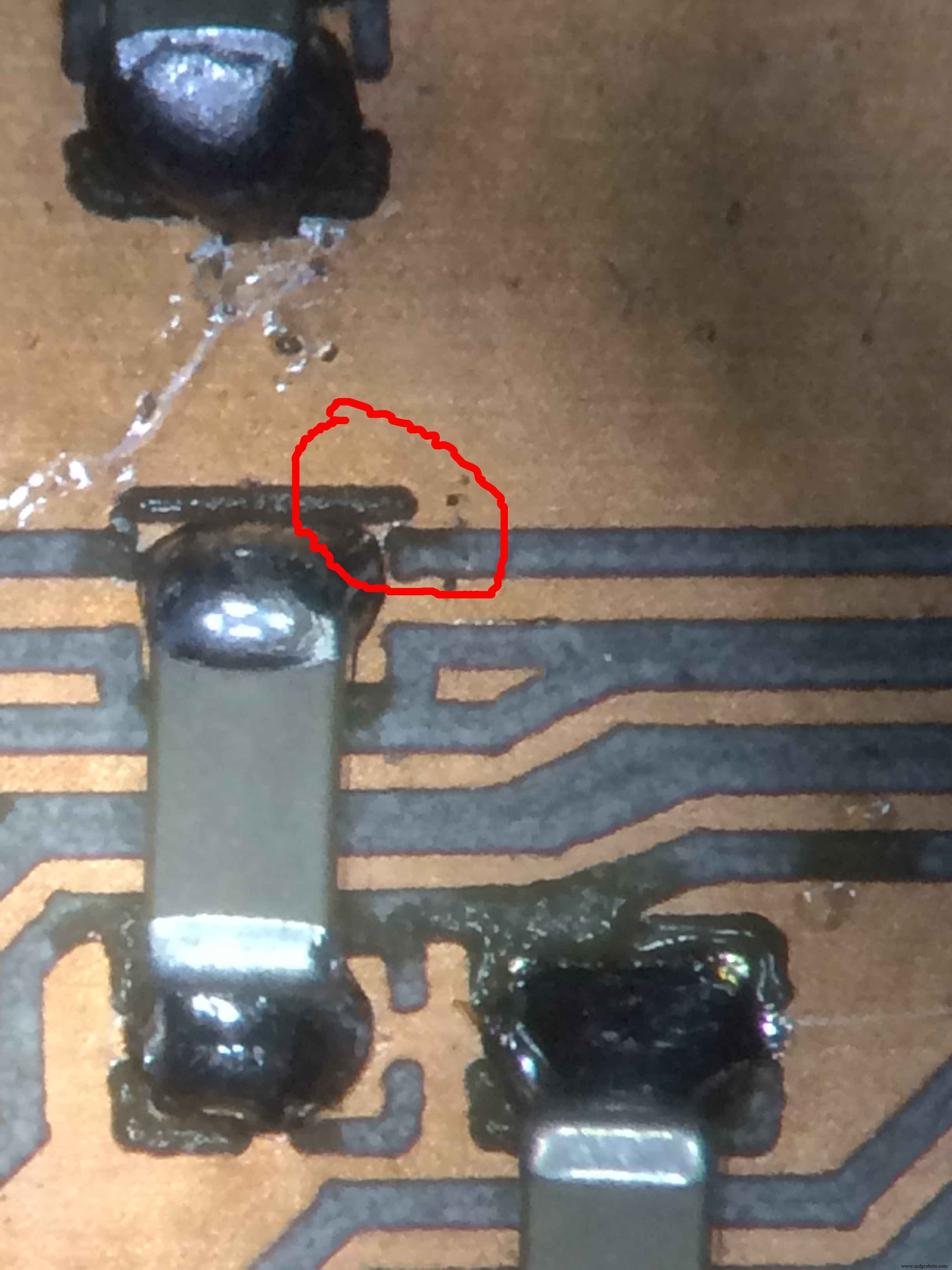
I fixed it by scratching with a knife, and increasing the isolation!
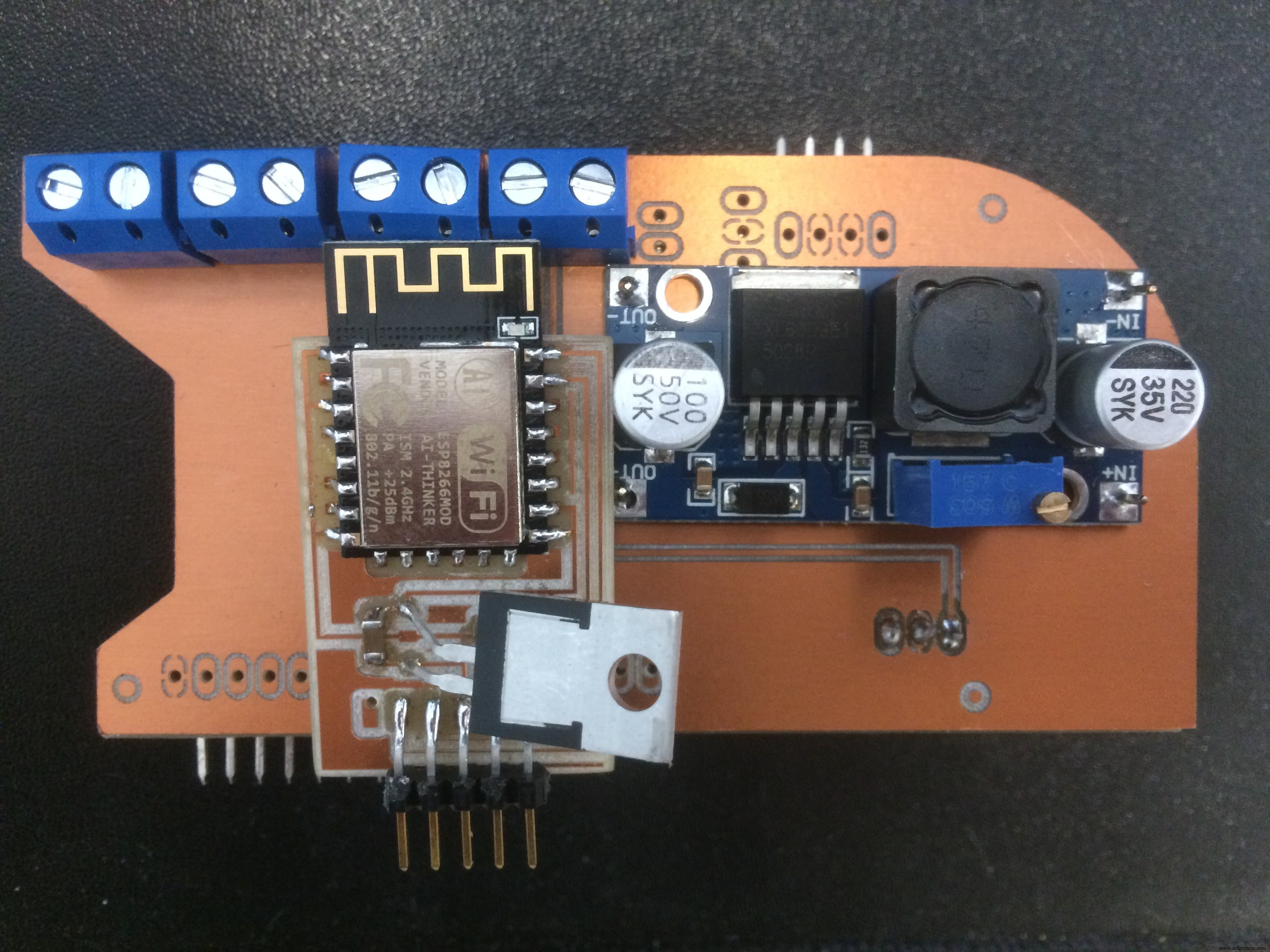
Another thing is placing the Step Up Voltage Reguator on the back side of my board.
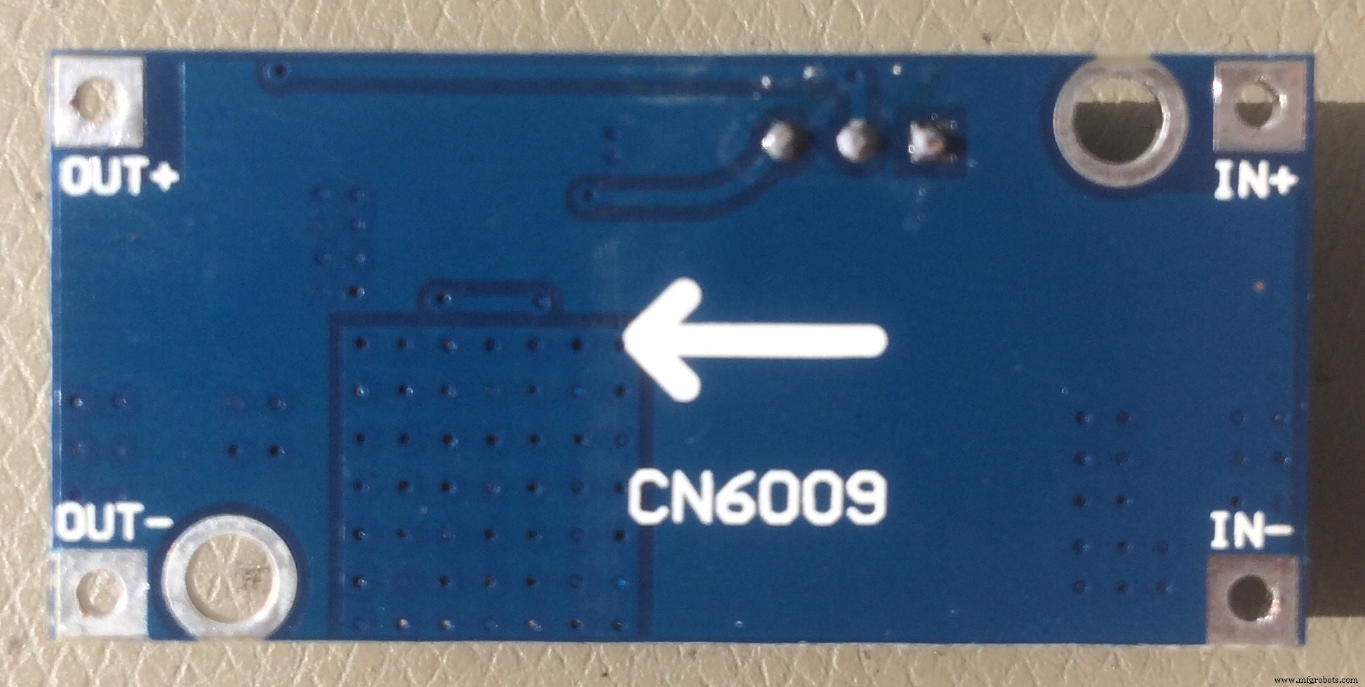
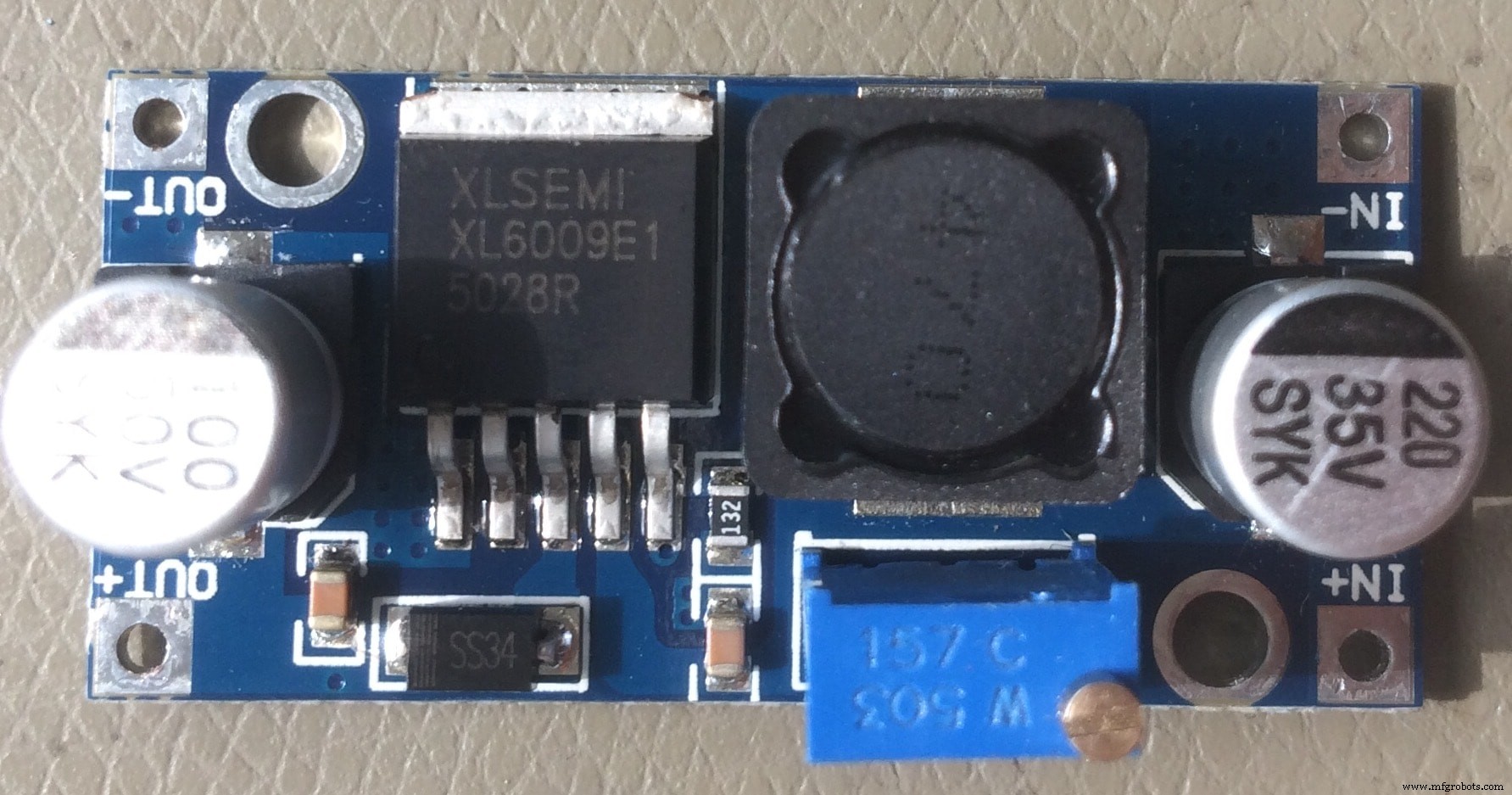
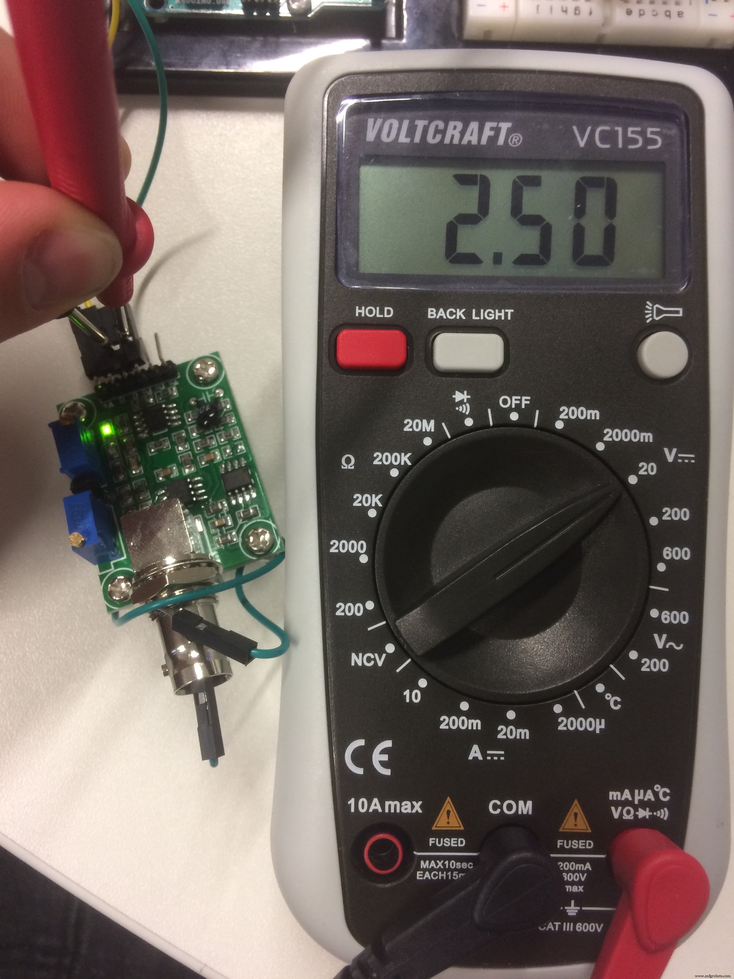
I measured the dimensions in advance, and designed predrilled holes to fix it with the pinheaders. But before soldering it on the back side, I have to calibrate it.
The idea is that when I power the board with 12V, the step up will output 24V necessary for the Ultrasonic Atomizer, which is connected to the MOSFET circuit
I used the bench power supply, with a fixed 12V, to measure the output voltage using a multimeter.
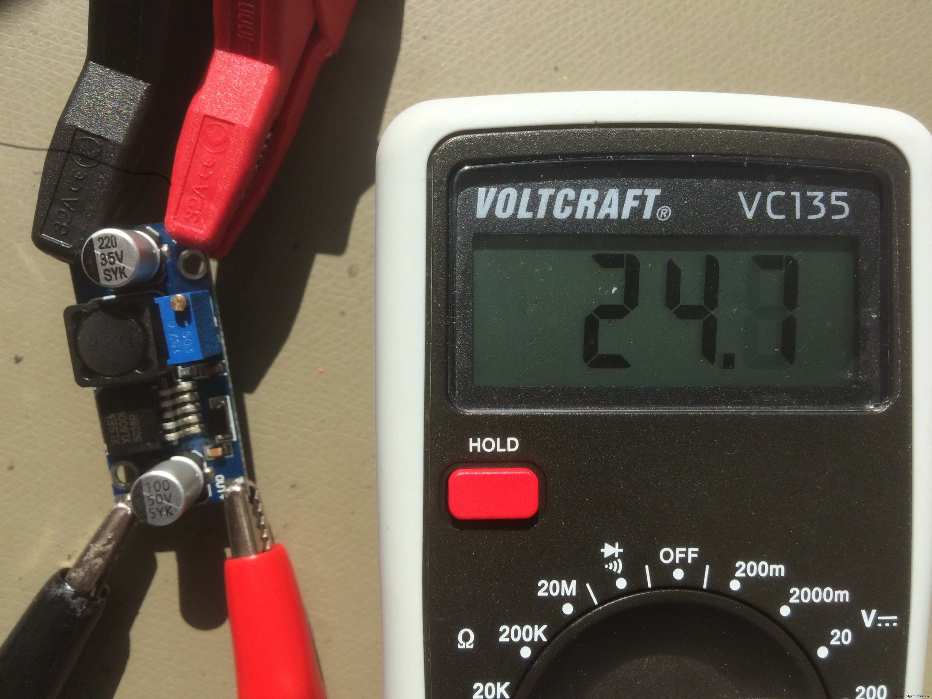
After I adjust the output to the one that I need, 24V in my case, I can solder it to the back side of my board!
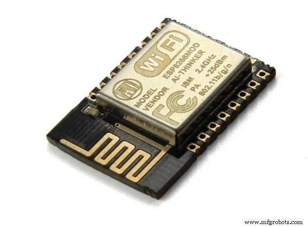
Also on the back side, I placed the WiFi board which I made during the Networking and Communications week!
So, here is The BEAST :
A HERO picture for those who may think that it was easy, and everything went smooth :D
Download Files:
GIY Schematics (.sch)
GIY Layout (.brd)
Board#1 Internal Cut(.png)
Board#1 External Cut (.png)
Board#2 Internal Cut (.png)
Board#2 External Cut (.png)
Wiring &Embedded programming (I/O Devices)
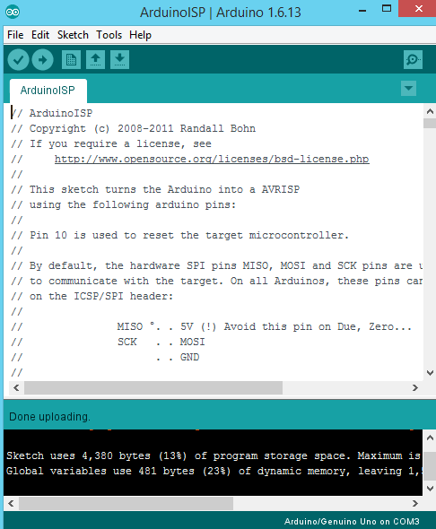
To program my board I used Arduino IDE . I connect the arduino board to the USB hub, in the tools menu select the right board (Arduino Leonardo) and the port, after go to File --> examples and open the Arduino as ISP sketch. Unggah kodenya.
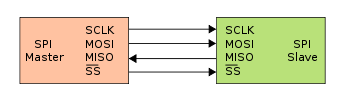
After I see done uploading, which means that the code is uploaded to the board, I disconnect the arduino from the PC. The next step is to connect my PCB board to Arduino using some wires. The connection scheme is this one:
- SCLK:Serial Clock (output from master) ----------> Arduino Pin 13
- MOSI:Master Output Slave Input ----------> Arduino Pin 11
- MISO:Master Input Slave Output ----------> Arduino Pin 12
- VCC:Positive supply voltage ----------> Arduino VCC
- GND:Ground ----------> Arduino GND
- RST:----------> Arduino Pin 10
I connect the arduino board to the USB hub. Under Tools select the right board, select Arduino as ISP programmer, double check the parameters, and press the Burn Bootloader button.
And I see Done Uploading! Good sign)
To test the board, I upload the basic Blink example code:
Ohh, I LOVE that BLINK :D Now let's go to sensors!
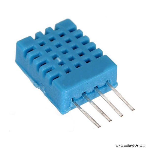
First sensor that I want to use is DHT11 - Temperature &Humidity Sensor
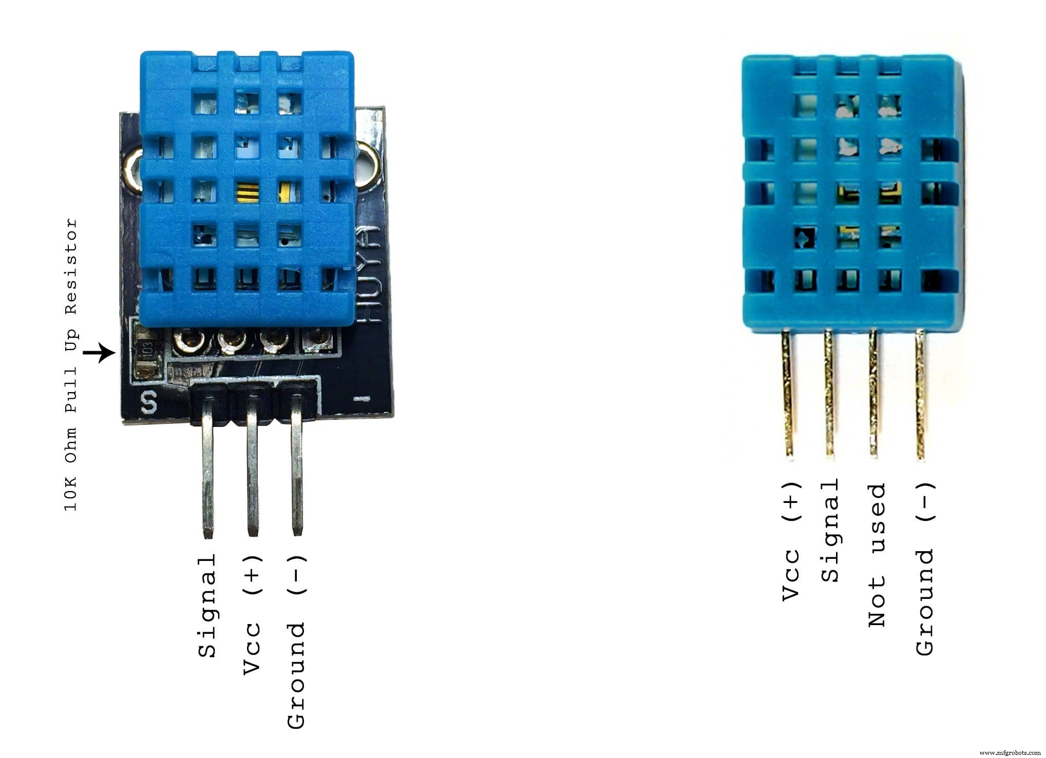
These sensors are very basic and slow, but are great for hobbyists who want to do some basic data logging. The DHT sensors are made of two parts, a capacitive humidity sensor and a thermistor. There is also a very basic chip inside that does some analog to digital conversion and spits out a digital signal with the temperature and humidity. The digital signal is fairly easy to read using any microcontroller.
Some characteristics:
- 2.5mA max current use during conversion (while requesting data)
- Good for 20-80% humidity readings with 5% accuracy
- Good for 0-50°C temperature readings ±2°C accuracy
- No more than 1 Hz sampling rate (once every second)
- Body size 15.5mm x 12mm x 5.5mm
The wiring is pretty easy, just VCC, GND, and any Digital Pin! In my case, I designed in advance the connection for this sensor.
To test it, I will upload a simple sketch. The sketch includes the library DHT.h
So here is the code:
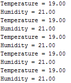
// DHT11 Temperature and Humidity Sensors Example#include "DHT.h" //include DHT library#define DHTPIN 2 //define as DHTPIN the Pin 2 used to connect the Sensor#define DHTTYPE DHT11 //define the sensor used(DHT11)DHT dht(DHTPIN, DHTTYPE); //create an instance of DHTvoid setup() { Serial.begin(9600); //initialize the Serial communication dht.begin(); //initialize the Serial communication}void loop() { float h =dht.readHumidity(); // reading Humidity float t =dht.readTemperature(); // read Temperature as Celsius (the default) Serial.print("Temperature ="); Serial.println(t, 2); //print the temperature Serial.print("Humidity =");; Serial.println(h, 2); //print the humidity delay(2000); //wait 2 seconds }
When I open the Serial Monitor, this is what I get:
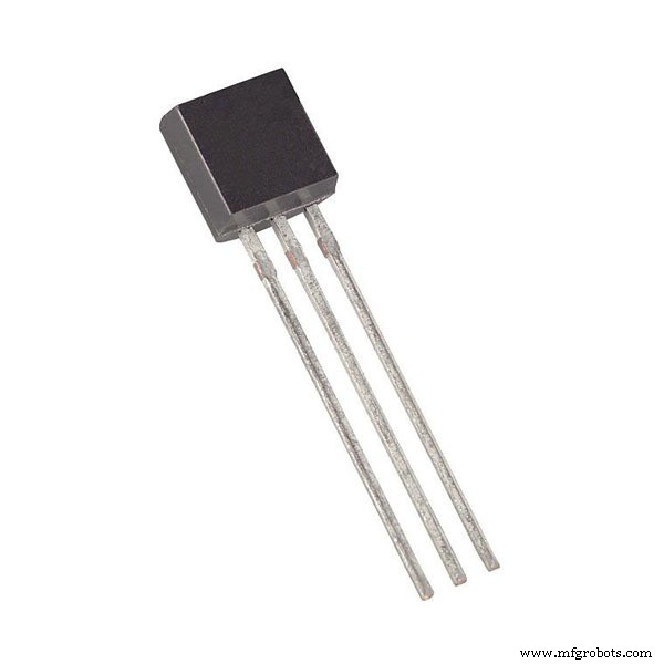
Another sensor which I want to use is DS18B20 - One Wire Digital Temperature Sensor
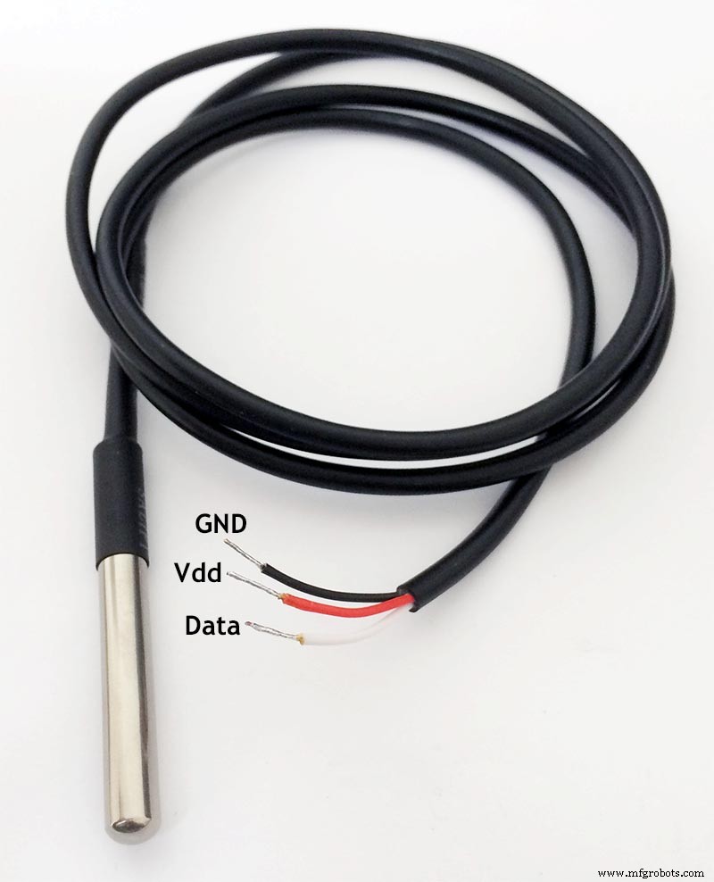
DS18B20 is 1-Wire digital temperature sensor from Maxim IC. Reports degrees in Celsius with 9 to 12-bit precision, from -55 to 125 (+/-0.5). Each sensor has a unique 64-Bit Serial number etched into it - allows for a huge number of sensors to be used on one data bus.
This is by far one of the most simple digital sensors to hookup. Aside from power and ground, it has a single digital signal pin that I will be connecting to digital pin which I designed in advance. It also requires a 4.7k pull-up resistor between the signal and power pin, which unfortunately I forgot to place on my PCB. That is why, I will solder it manually directly to the sensor cables.
Before I start, I have to download the libraries:OneWire.h and DallasTemperature.h
Upload the following sketch:
// First we include the libraries#include #include #define ONE_WIRE_BUS 3 // Setup a oneWire instance to communicate with any OneWire devices, (not just Maxim/Dallas temperature ICs) OneWire oneWire(ONE_WIRE_BUS); // Berikan referensi oneWire kami ke Suhu Dallas. DallasTemperature sensors(&oneWire);void setup(void) { // start serial port Serial.begin(9600); sensor.mulai(); } void loop(void) { // call sensors.requestTemperatures() to issue a global temperature (request to all devices on the bus)sensors.requestTemperatures(); // Send the command to get temperature readings Serial.print("Temperature is:"); Serial.print(sensors.getTempCByIndex(0)); //You can have more than one DS18B20 on the same bus. 0 refers to the first IC on the wire delay(1000); }
The funny thing is that after I successfully programmed the sensor, It stopped working while I was integrating all the sensors together! I spend quite a long time trying to figure out why it does not work, but due to the limited time, I decided to use another DS18B20 sensor which was available in our FabLab stock, and waterproof it by myself!
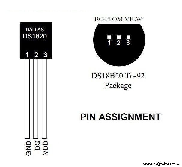
So I took the sensor, and used the datasheet to properly solder the cables, and isolate them from each other using shrink tubes
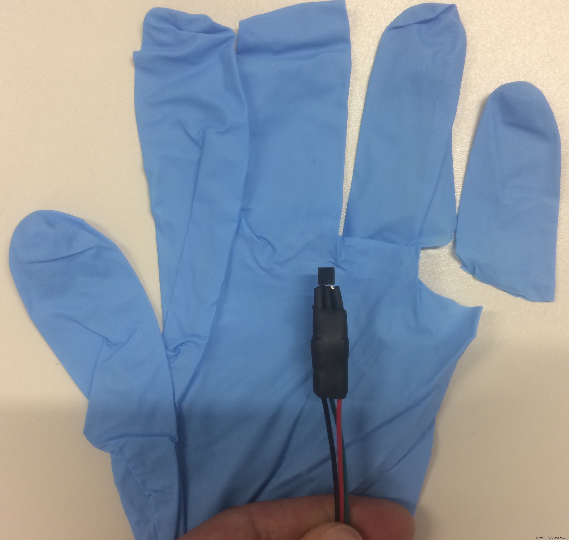
I guess you have got the idea how I am going to waterproof it, right? :D Mama ama engineer!
Said &DONE!
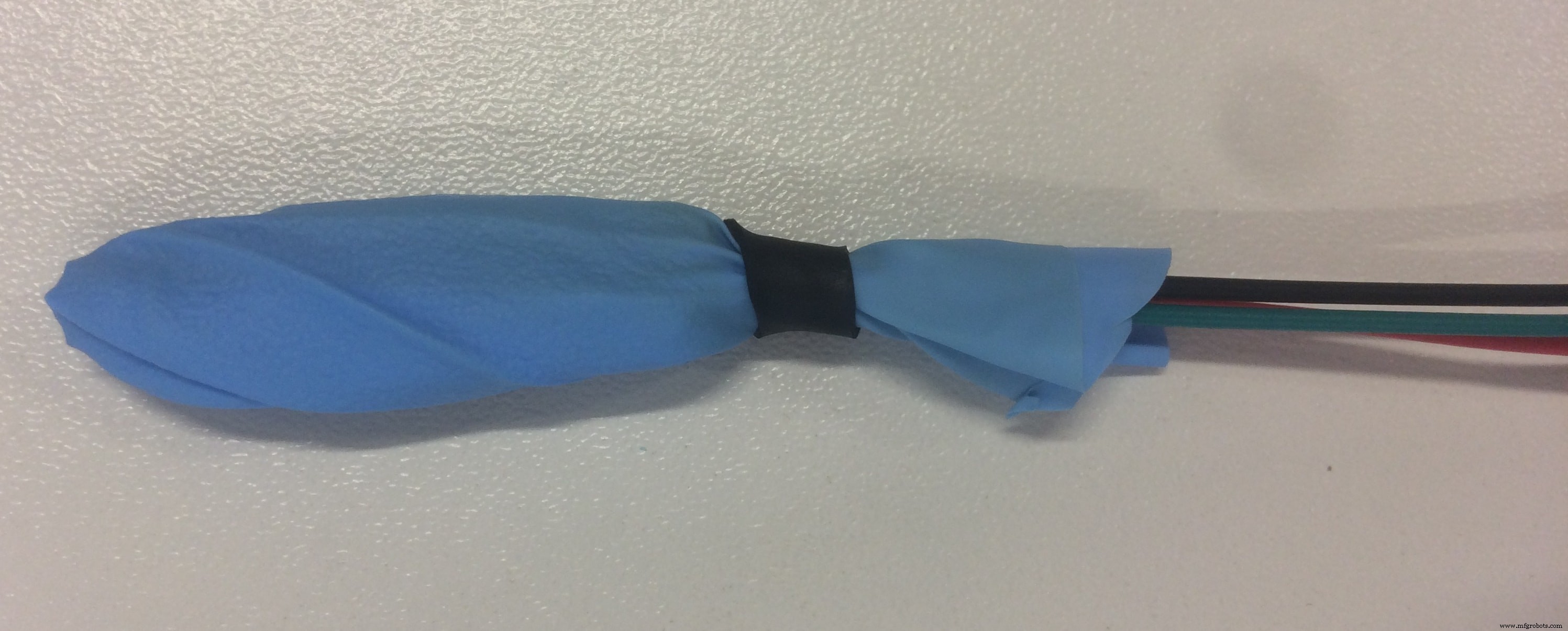
Yeah, I know what it looks like :D but I assure you, its just a hand waterproof sensor. The most important is that it works, and does not leak when submerged in water!
And we go to the next sensor which is LDR =Light Dependent Resistor
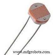
LDR is a passive electronic component, basically a resistor which has a resistance that varies depending of the light intensity. The resistance is very high in darkness, almost high as 1MΩ but when there is light that falls on the LDR, the resistance is falling down to a few KΩ (10-20kΩ @ 10 lux, 2-4kOmega; @ 100 lux) depending on the model.
The LDR gives out an analog voltage when connected to Vcc (5V), which varies in magnitude in direct proportion to the input light intensity on it. That is, the greater the intensity of light, the greater the corresponding voltage from the LDR will be. Since the LDR gives out an analog voltage, it is connected to the analog input pin on the Arduino. The Arduino, with its built-in ADC (Analog to Digital Converter), then converts the analog voltage (from 0-5V) into a digital value in the range of (0-1023). When there is sufficient light in its environment or on its surface, the converted digital values read from the LDR through the Arduino will be in the range of 800-1023.
Here is the sketch code to test the sensor:
int sensorPin =A0; /* select the input pin for LDR */int sensorValue =0; /* variable to store the value coming from the sensor */void setup(void) { Serial.begin(9600); /* start serial port */} void loop(void) { sensorValue =analogRead(sensorPin); // read the value from the sensor // We'll have a few threshholds, qualitatively determined Serial.print("LDR Value ="); Serial.print(sensorValue); if (sensorValue <100) { Serial.println(" (Dark)"); } else if (sensorValue <200) { Serial.println(" (Dim)"); } else if (sensorValue <500) { Serial.println(" (Light)"); } else if (sensorValue <800) { Serial.println(" (Bright)"); } else { Serial.println(" (Very bright)"); } delay(3000);}
Next is Water Level Sensor
I want to have a water level sensor in order to receive an alarm when the water container is empty, and its time to add some water. Because I did not think about it in advance, and we did not have any water level sensor in our stock, I decided that I can make my own water sensor!
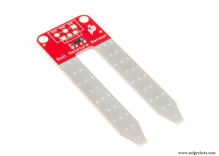
I decided to use the materials available, in my case the Soil Moisture Sensor . The basic principle of the water level sensor is to measure electric conductivity, which is the same for the soil moisture sensor. I thought that If I can calibrate the sensor in a way that will fulfil my requirements, I can use the moisture sensor like an water level sensor) In principle, this is an analog sensor and the data that we will read will be values from 0 to 1024, and the rest is just math!
But as it often happens, the reality is slightly different. When the sensor is not in touch with the water, the analog value is 0, and when I submerge only the tip, the value goes to 800. I used the following sketch to read the values:
/* Print values from analog pin A4 to serial monitor */void setup(){ Serial.begin(9600); }void loop(){ Serial.println(analogRead(A4)); delay(100);}
After I can read the values, I calibrated the sensor to give out three different responses:EMPTY! - when the value is 0, LOW when the values are around 800, and Full when the values are more than 900!
Graphic LCD Display 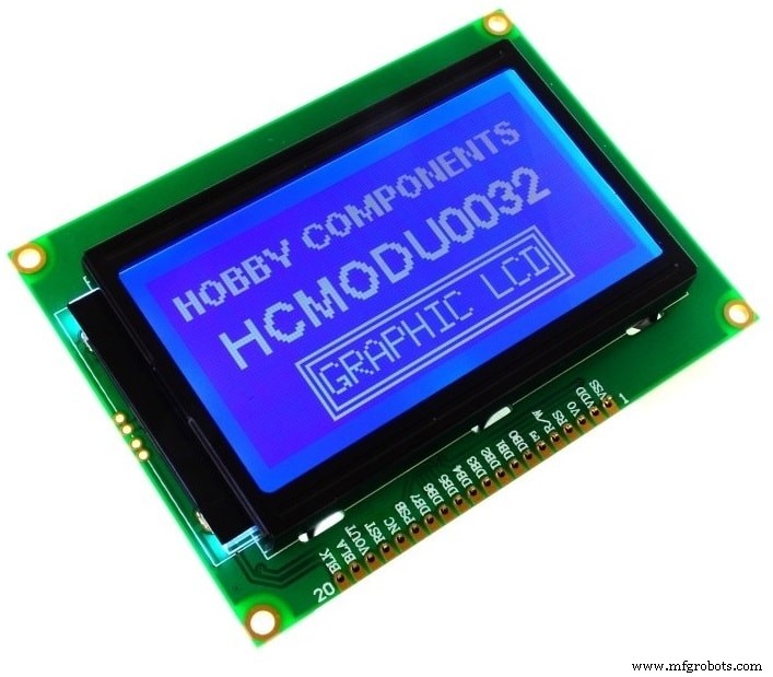
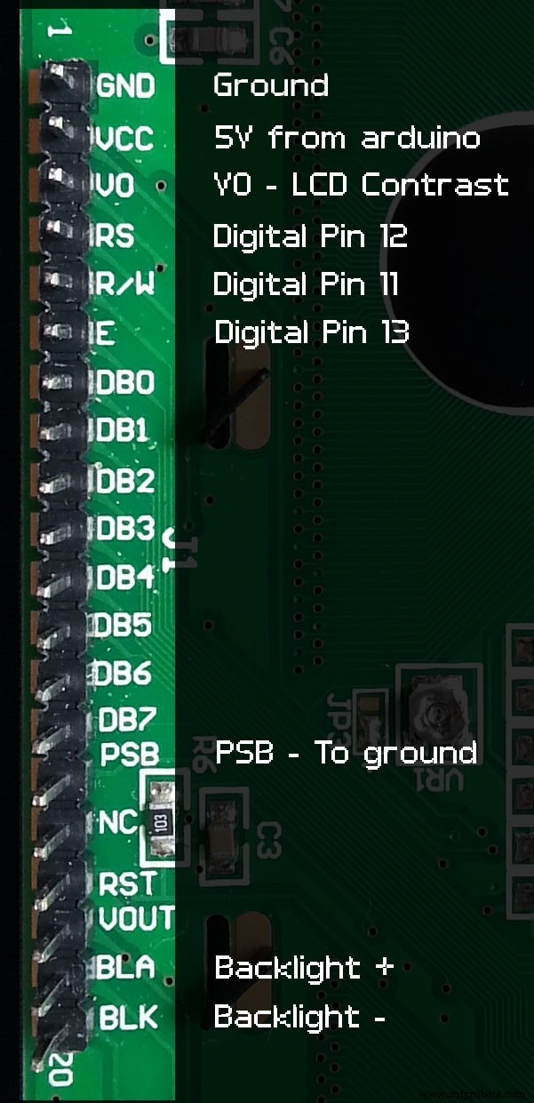
Because usually the LCD displays use a lot of pins, I had to find a way to connect the 128×64 screen in another way, and I DID!!! This way alows using only 3 Digital Pins on the board which is awesome because I may need the rest of the pins for other stuff, and it does not create a mess of wires. I premade the pins for the LCD on my PCB, and this is how I connected everything:
After I connect the LCD, It's time to programm it!
First of all, I have to download the U8glib library from HERE. Another important thing is the declared pins used in the code. The one I used are the following: U8GLIB_ST7920_128X64 u8g(4, 12, 6, U8G_PIN_NONE)
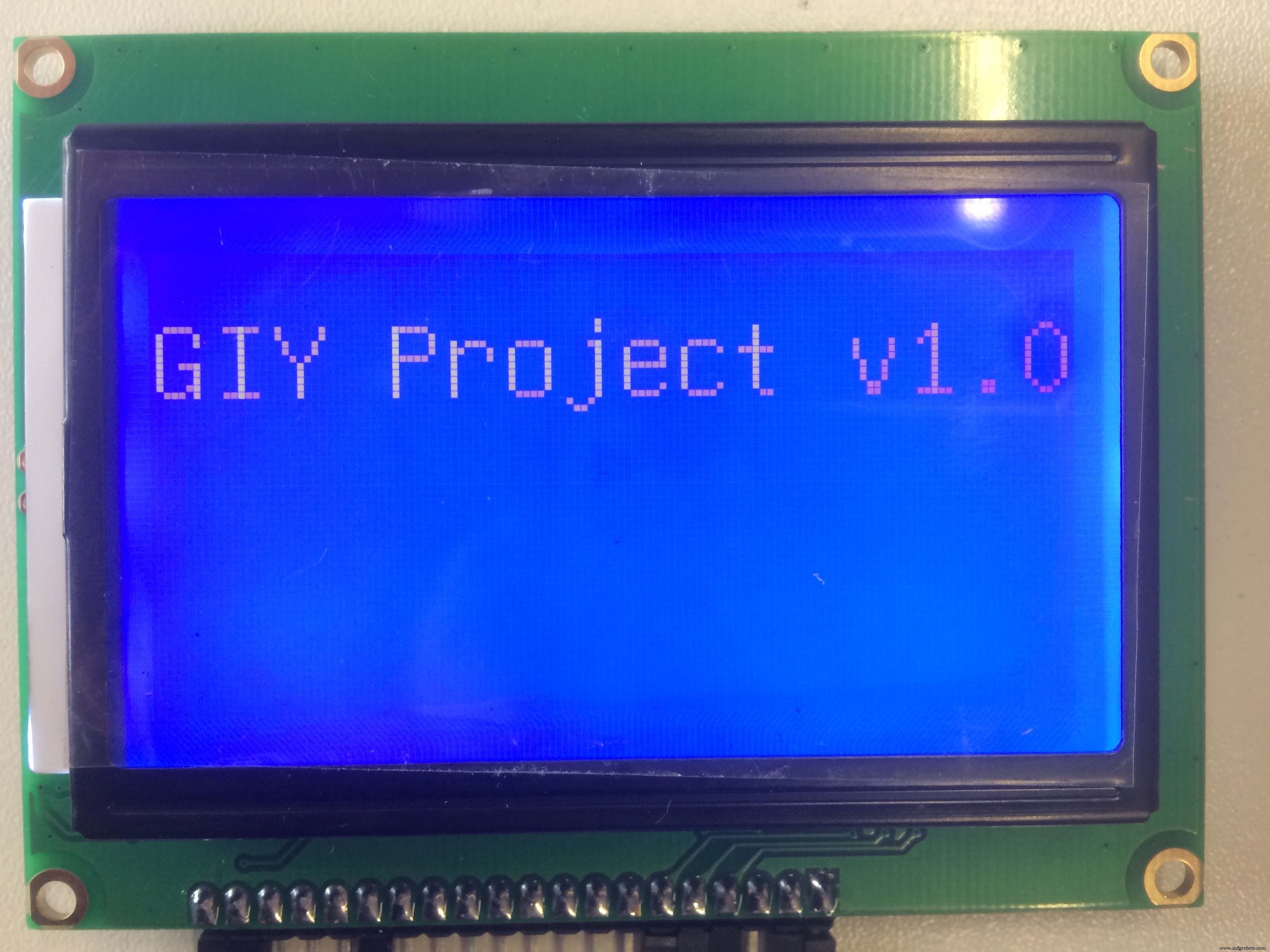
Using the "HELLO WORLD" library example, I came up with this test code:
#include "U8glib.h"U8GLIB_ST7920_128X64 u8g(4, 12, 6, U8G_PIN_NONE);void draw(void) { // graphic commands to redraw the complete screen should be placed here u8g.setFont(u8g_font_unifont); u8g.setPrintPos(0, 20); // call procedure from base class, http://arduino.cc/en/Serial/Print u8g.print("GIY Project v1.0!");}void setup(void) { // flip screen, if required // u8g.setRot180();}void loop(void) { // picture loop u8g.firstPage(); melakukan { menggambar(); } while( u8g.nextPage() ); // rebuild the picture after some delay delay(500);}
And this is what I get:
One cool idea that came to my mind was to display the FabLab logo for some seconds, all the time when the display is powered. I spent quite a lot of time on doing this, but I finally did it! In order to display it on the Graphic LCD, I had to have a (.bmp) format picture, and display it as a bitmap.
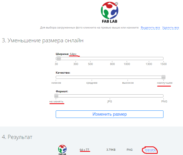
First thing which I did was download the FabLab logo from the internet as a (.png) file, and reduce it significantly in size, so it fits my small LCD borders. I used the following online service to do that:LINK
These are the configurations I used:
The next step is to convert my small picture into (.bmp) format. I used the following online service to do that:LINK
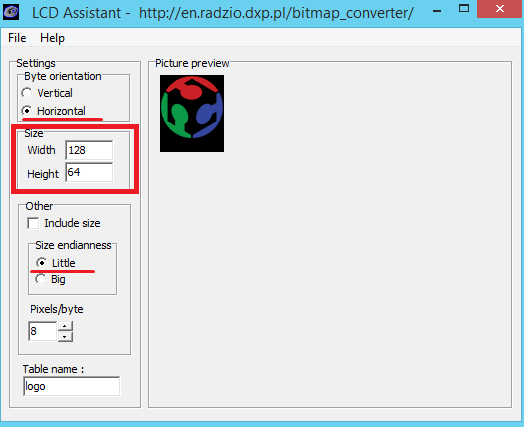
Now, after I have my (.bmp) file, in order to place it into my code, I have to convert it into HEX Himpunan. I used a nice tool called LCD Assistant . To load up an image in LCD Assistant, go to File> Load Image. A preview of the image should open up, make sure it’s the right size – 128 pixels wide, 64 pixels tall . Also make sure the Byte orientation is set to Horizontal and the Size endianness is set to Little . These are the configurations for my LCD Display:
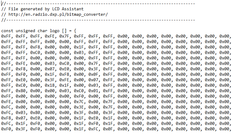
Then I go to File> Save output to generate a temporary text mengajukan. Open that text file to have a look at my shiny new array.
pH Sensor 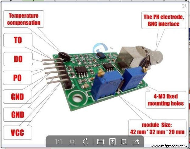
I should admit that this is the most tricky sensor from all that I played with! It is really hard to find any info about the sensor which I am using (logo ph sensor v1.1) , so I decided to make a detailed description about it!
The probe is like a (tiny) battery when placed in a liquid. Depending the pH it output a positive or negative voltage of a couple of millivolts. This value is too small and other tech stuff like impedance make it unusable directly with an Arduino, that's why you need an "op amp". The op amp board just convert the millivolts of the probe into to something acceptable for Arduino (positive between 0 and 5v).
There are 3 common buffer solutions used for pH measurement:pH 4.01, pH 6.86 and pH 9.18 (7.0 and 10.0 exists). I suggest the powder instead the liquid because it's cheaper, expire after longer and the powder can't be contaminated (vs bottle). You should read the product instructions but usually you have to put the content of the bag into 250ml of water and stir. You can use any water with an average pH (6-8) because the powder will saturate the water at the correct pH level. I personally use tap water (pH 7.4) and didn't see any difference between distilled, and demineralized water. Buffers are not stable in the time, this means that you cannot keep the solution for weeks or months.
Now let's talk more about the sensor that I am using!
- Pin To:Should be the temperature but I can't make it work
- Pin Po:Analog input signal
- Pin To:Should be the temperature but I can't make it work
- Pin Do:High/Low 3.3v adjustable limit.
- Pin G/GND:Probe ground. It is useful when the ground is not the same as your Arduino. In some circumstances the ground voltage of the liquid to measure can be different.
- Pin G/GND:Power ground (direct from the board).
- Pin V+/VCC:Input power 5V DC (direct from the board).
- Blue potentiometer (close to BNC):pH offset.
- Blue potentiometer (close to pins):limit adjustment.
Now let's try to calibrate the sensor! There are 2 different parameters, the "offset" value and the "step" value
The offset is the shifting of all pH values to a specific voltage range. If a pH 7 output a voltage of 2.2v and pH 8 a voltage of 2.1v, then a shift of +0.3v move the pH 7 to 2.5v and the pH 8 to 2.4v. This can be done on the board or via software but it's probably easier on the board because it's probe independent and there are less programming to do.
Connect GND (both) and Vcc to Arduino GND and 5v. Remove the probe and do a short circuit between the the small BNC hole and the external part of BNC. Put a voltmeter (or Arduino) to measure the voltage between GND and Po. Adjust the pot (close BNC) until the output is 2.5v. Now the pH 7 have an exact value of 2.5v (511 with analogRead function) because the probe will output 0 millivolt.
To calibrate the steps I need one or more buffer solutions depending on the range and precision required. Ideally it is better to know the range of the measure with the system. I use water between pH 5 and pH 7, then I choose the buffer 4.01 (and 6.86 to verify my stuff). If you usually measure pH between 8 and 10 choose buffer 9.18 (eventually 6.86 also).
I connect the (clean) probe and put it in the buffer, then let it stabilize for a minute. I know it's stable when it goes up and down (3.04 then 3.05 then 3.03 then 3.04).Take note of the voltmeter (or Arduino) value, in my example it's 3.05v.
That's all, now I can use it with the code below.
int ph_pin =A7; //This is the pin number connected to Povoid setup() { Serial.begin(9600);}void loop() { int measure =analogRead(ph_pin); Serial.print("Measure:"); Serial.print(measure); double voltage =5 / 1024.0 * measure; //classic digital to voltage conversion Serial.print("\tVoltage:"); Serial.print(voltage, 3); // PH_step =(voltage@PH7 - voltage@PH4) / (PH7 - PH4) // PH_probe =PH7 - ((voltage@PH7 - voltage@probe) / PH_step) float Po =7 + ((2.5 - voltage) / 0.18); Serial.print("\tPH:"); Serial.print(Po, 3); Serial.println(""); delay(2000);}
The PH_step calculation is quite simple. I take the difference between the two known voltage, in my example 2.5v@pH7 and [email protected] which is -0.55v. It's the voltage range equivalent of the pH range from 7 to 4.01, which is 2.99 pH units. A small division of the voltage by pH units gives a volts per pH number (0, 1839... in my case).
The PH_probe is calculated by taking the known pH 7 voltage (2.5v) where we add some PH_step to match the probe voltage. This means that a pH of 8 has a voltage value of 2.5v (pH 7) + 0.1839 (1 unit/step); pH 9 then is 2.5v + 0.1839 + 0.1839 =2.87v.
No magic, JUST MATH :D
MOSFET output:
I connected the RGB LED stripe and the Ultrasonic Atomizer to the MOSFET circuit outputs, which are controlled by digital pins. For the LED lights, I stated in the setup digitalWrite (LED, HIGH); , which means that the LED will switch on all the time when the system is powered. For the Fog maker, I made an If function depending on the water level value. If there is water, the fog maker is ON, if there is no water, EMPTY!, then the fog is OFF!
Now Let's put things together!
Here I came up with my final code:
#include "dht.h"#include "U8glib.h"#include #include #define DHT11_PIN 2 // what digital pin we're connected to#define ONE_WIRE_BUS 3#define WATER_LEVEL A4#define LDR_PIN A3#define PH_PIN A5#define GROW_LIGHT 10#define FOG_PUMP 13int waterLevel;int LightLevel;int pH;dht DHT;OneWire oneWire(ONE_WIRE_BUS); DallasTemperature waterTemp(&oneWire);U8GLIB_ST7920_128X64 u8g(4, 12, 6, U8G_PIN_NONE);const unsigned char logo [] PROGMEM ={0xFF, 0xFF, 0xFF, 0xFE, 0x7F, 0xFF, 0xFF, 0xFF, 0x00, 0x00, 0x00, 0x00, 0x00, 0x00, 0x00, 0x00,0xFF, 0xFF, 0xFF, 0x00, 0x00, 0xFF, 0xFF, 0xFF, 0x00, 0x00, 0x00, 0x00, 0x00, 0x00, 0x00, 0x00,0xFF, 0xFF, 0xF8, 0x00, 0x00, 0x1F, 0xFF, 0xFF, 0x00, 0x00, 0x00, 0x00, 0x00, 0x00, 0x00, 0x00,0xFF, 0xFF, 0xC0, 0x00, 0x00, 0x03, 0xFF, 0xFF, 0x00, 0x00, 0x00, 0x00, 0x00, 0x00, 0x00, 0x00,0xFF, 0xFF, 0x00, 0x00, 0x00, 0x00, 0xFF, 0xFF, 0x00, 0x00, 0x00, 0x00, 0x00, 0x00, 0x00, 0x00,0xFF, 0xFE, 0x00, 0x03, 0xC0, 0x00, 0x7F, 0xFF, 0x00, 0x00, 0x00, 0x00, 0x00, 0x00, 0x00, 0x00,0xFF, 0xF8, 0x00, 0x07, 0xE0, 0x00, 0x3F, 0xFF, 0x00, 0x00, 0x00, 0x00, 0x00, 0x00, 0x00, 0x00,0xFF, 0xF0, 0x00, 0x1F, 0xF8, 0x00, 0x0F, 0xFF, 0x00, 0x00, 0x00, 0x00, 0x00, 0x00, 0x00, 0x00,0xFF, 0xE0, 0x00, 0x3F, 0xFE, 0x00, 0x07, 0xFF, 0x00, 0x00, 0x00, 0x00, 0x00, 0x00, 0x00, 0x00,0xFF, 0xC0, 0x00, 0 x18, 0x1F, 0x00, 0x03, 0xFF, 0x00, 0x00, 0x00, 0x00, 0x00, 0x00, 0x00, 0x00,0xFF, 0x80, 0x00, 0x00, 0x03, 0xC0, 0x01, 0xFF, 0x00, 0x00, 0x00, 0x00, 0x00, 0x00, 0x00, 0x00,0xFF, 0x00, 0x00, 0x00, 0x00, 0xF0, 0x00, 0xFF, 0x00, 0x00, 0x00, 0x00, 0x00, 0x00, 0x00, 0x00,0xFE, 0x00, 0x00, 0x00, 0x00, 0x7C, 0x00, 0x7F, 0x00, 0x00, 0x00, 0x00, 0x00, 0x00, 0x00, 0x00,0xFC, 0x00, 0x00, 0x00, 0x00, 0x3E, 0x00, 0x7F, 0x00, 0x00, 0x00, 0x00, 0x00, 0x00, 0x00, 0x00,0xFC, 0x03, 0x80, 0x00, 0x00, 0x3F, 0x80, 0x3F, 0x00, 0x00, 0x00, 0x00, 0x00, 0x00, 0x00, 0x00,0xF8, 0x07, 0xE0, 0x00, 0x00, 0x1F, 0xE0, 0x1F, 0x00, 0x00, 0x00, 0x00, 0x00, 0x00, 0x00, 0x00,0xFC, 0x1F, 0xF0, 0x00, 0x00, 0x1F, 0xF0, 0x1F, 0x00, 0x00, 0x00, 0x00, 0x00, 0x00, 0x00, 0x00,0xF0, 0x3F, 0xF0, 0x00, 0x00, 0x1F, 0xFC, 0x0F, 0x00, 0x00, 0x00, 0x00, 0x00, 0x00, 0x00, 0x00,0xF0, 0xFF, 0xF0, 0x00, 0x00, 0x1F, 0xFF, 0x0F, 0x00, 0x00, 0x00, 0x00, 0x00, 0x00, 0x00, 0x00,0xE0, 0xFF, 0xF0, 0x00, 0x00, 0x3F, 0xFF, 0x07, 0x00, 0x00, 0x00, 0x0 0, 0x00, 0x00, 0x00, 0x00,0xE0, 0xFF, 0xF0, 0x00, 0x00, 0x3F, 0xFF, 0x07, 0x00, 0x00, 0x00, 0x00, 0x00, 0x00, 0x00, 0x00,0xC0, 0xFF, 0xF8, 0x00, 0x00, 0x7F, 0xFF, 0x03, 0x00, 0x00, 0x00, 0x00, 0x00, 0x00, 0x00, 0x00,0xC0, 0xFF, 0xFC, 0x00, 0x00, 0xFF, 0xFF, 0x03, 0x00, 0x00, 0x00, 0x00, 0x00, 0x00, 0x00, 0x00,0xC0, 0xFF, 0xFF, 0x00, 0x01, 0xFF, 0xFF, 0x03, 0x00, 0x00, 0x00, 0x00, 0x00, 0x00, 0x00, 0x00,0x80, 0xFF, 0xFF, 0xC0, 0x07, 0xFF, 0xFF, 0x01, 0x00, 0x00, 0x00, 0x00, 0x00, 0x00, 0x00, 0x00,0x80, 0xFF, 0xFF, 0xFF, 0xFF, 0xFF, 0xFF, 0x01, 0x00, 0x00, 0x00, 0x00, 0x00, 0x00, 0x00, 0x00,0x80, 0xFF, 0xFF, 0xFF, 0xFF, 0xFF, 0xFF, 0x01, 0x00, 0x00, 0x00, 0x00, 0x00, 0x00, 0x00, 0x00,0x80, 0xFF, 0xFF, 0xFF, 0xFF, 0xFF, 0xFF, 0x01, 0x00, 0x00, 0x00, 0x00, 0x00, 0x00, 0x00, 0x00,0x80, 0xFE, 0x1F, 0xFF, 0xFF, 0xF0, 0x3C, 0x01, 0x00, 0x00, 0x00, 0x00, 0x00, 0x00, 0x00, 0x00,0x80, 0xF8, 0x03, 0xFF, 0xFF, 0xC0, 0x10, 0x01, 0x00, 0x00, 0x00, 0x00, 0x00, 0x00, 0x00, 0x00,0x80, 0xF0, 0x01, 0xFF, 0xFF, 0x80, 0x00, 0x01, 0x00, 0x00, 0x00, 0x00, 0x00, 0x00, 0x00, 0x00,0x00, 0xF0, 0x00, 0xFF, 0xFF, 0x00, 0x00, 0x01, 0x00, 0x00, 0x00, 0x00, 0x00, 0x00, 0x00, 0x00,0x00, 0xE0, 0x00, 0x7F, 0xFE, 0x00, 0x00, 0x01, 0x00, 0x00, 0x00, 0x00, 0x00, 0x00, 0x00, 0x00,0x80, 0xE0, 0x00, 0x3F, 0xFC, 0x00, 0x00, 0x01, 0x00, 0x00, 0x00, 0x00, 0x00, 0x00, 0x00, 0x00,0x80, 0xE0, 0x00, 0x1F, 0xFC, 0x00, 0x00, 0x01, 0x00, 0x00, 0x00, 0x00, 0x00, 0x00, 0x00, 0x00,0x80, 0xE0, 0x00, 0x1F, 0xF8, 0x00, 0x00, 0x01, 0x00, 0x00, 0x00, 0x00, 0x00, 0x00, 0x00, 0x00,0x80, 0xE0, 0x00, 0x0F, 0xF8, 0x00, 0x00, 0x01, 0x00, 0x00, 0x00, 0x00, 0x00, 0x00, 0x00, 0x00,0x80, 0xE0, 0x00, 0x0F, 0xF0, 0x00, 0x00, 0x01, 0x00, 0x00, 0x00, 0x00, 0x00, 0x00, 0x00, 0x00,0x80, 0xE0, 0x00, 0x0F, 0xF0, 0x00, 0x01, 0x01, 0x00, 0x00, 0x00, 0x00, 0x00, 0x00, 0x00, 0x00,0x80, 0xE0, 0x00, 0x07, 0xF0, 0x00, 0x07, 0x01, 0x00, 0x00, 0x00, 0x00, 0x00, 0x00, 0x00, 0x00,0xC0, 0xF0, 0x00, 0x07, 0xF0, 0x00, 0x07, 0x03, 0x00, 0x00, 0x00, 0x00, 0x 00, 0x00, 0x00, 0x00,0xC0, 0xF0, 0x00, 0x07, 0xF0, 0x00, 0x0F, 0x03, 0x00, 0x00, 0x00, 0x00, 0x00, 0x00, 0x00, 0x00,0xC0, 0xF8, 0x00, 0x07, 0xF0, 0x00, 0x0F, 0x03, 0x00, 0x00, 0x00, 0x00, 0x00, 0x00, 0x00, 0x00,0xC0, 0xF8, 0x00, 0x07, 0xF0, 0x00, 0x1F, 0x07, 0x00, 0x00, 0x00, 0x00, 0x00, 0x00, 0x00, 0x00,0xE0, 0xFC, 0x00, 0x07, 0xF0, 0x00, 0x1F, 0x07, 0x00, 0x00, 0x00, 0x00, 0x00, 0x00, 0x00, 0x00,0xE0, 0xFE, 0x00, 0x0F, 0xF0, 0x00, 0x3F, 0x07, 0x00, 0x00, 0x00, 0x00, 0x00, 0x00, 0x00, 0x00,0xF0, 0x3E, 0x00, 0x0F, 0xF0, 0x00, 0x7C, 0x0F, 0x00, 0x00, 0x00, 0x00, 0x00, 0x00, 0x00, 0x00,0xF0, 0x1E, 0x00, 0x1F, 0xF8, 0x00, 0xF8, 0x0F, 0x00, 0x00, 0x00, 0x00, 0x00, 0x00, 0x00, 0x00,0xF8, 0x06, 0x00, 0x1F, 0xFC, 0x01, 0xE0, 0x1F, 0x00, 0x00, 0x00, 0x00, 0x00, 0x00, 0x00, 0x00,0xFC, 0x00, 0x00, 0x7F, 0xFF, 0x0F, 0x80, 0x3F, 0x00, 0x00, 0x00, 0x00, 0x00, 0x00, 0x00, 0x00,0xFC, 0x00, 0x00, 0x7F, 0xFF, 0xFF, 0x00, 0x3F, 0x00, 0x00, 0x00, 0x00, 0x00, 0x00, 0x00, 0x00,0xFE, 0x00, 0x00, 0x7F, 0xFF, 0xFC, 0x00, 0x7F, 0x00, 0x00, 0x00, 0x00, 0x00, 0x00, 0x00, 0x00,0xFF, 0x00, 0x00, 0x7F, 0xFF, 0xF0, 0x00, 0xFF, 0x00, 0x00, 0x00, 0x00, 0x00, 0x00, 0x00, 0x00,0xFF, 0x80, 0x00, 0x7F, 0xFF, 0xC0, 0x01, 0xFF, 0x00, 0x00, 0x00, 0x00, 0x00, 0x00, 0x00, 0x00,0xFF, 0xC0, 0x00, 0x7F, 0xFF, 0x80, 0x03, 0xFF, 0x00, 0x00, 0x00, 0x00, 0x00, 0x00, 0x00, 0x00,0xFF, 0xE0, 0x00, 0x7F, 0xFE, 0x00, 0x07, 0xFF, 0x00, 0x00, 0x00, 0x00, 0x00, 0x00, 0x00, 0x00,0xFF, 0xF0, 0x00, 0x1F, 0xF8, 0x00, 0x0F, 0xFF, 0x00, 0x00, 0x00, 0x00, 0x00, 0x00, 0x00, 0x00,0xFF, 0xF8, 0x00, 0x0F, 0xF0, 0x00, 0x1F, 0xFF, 0x00, 0x00, 0x00, 0x00, 0x00, 0x00, 0x00, 0x00,0xFF, 0xFC, 0x00, 0x03, 0xC0, 0x00, 0x3F, 0xFF, 0x00, 0x00, 0x00, 0x00, 0x00, 0x00, 0x00, 0x00,0xFF, 0xFF, 0x00, 0x00, 0x00, 0x00, 0xFF, 0xFF, 0x00, 0x00, 0x00, 0x00, 0x00, 0x00, 0x00, 0x00,0xFF, 0xFF, 0xC0, 0x00, 0x00, 0x03, 0xFF, 0xFF, 0x00, 0x00, 0x00, 0x00, 0x00, 0x00, 0x00, 0x00,0xFF, 0xFF, 0xF0, 0x00, 0x00, 0x1F, 0xFF, 0xFF, 0x00, 0x00, 0x00, 0x00, 0x00, 0 x00, 0x00, 0x00,0xFF, 0xFF, 0xFE, 0x00, 0x00, 0x7F, 0xFF, 0xFF, 0x00, 0x00, 0x00, 0x00, 0x00, 0x00, 0x00, 0x00,0xFF, 0xFF, 0xFF, 0xFD, 0x3F, 0xFF, 0xFF, 0xFF, 0x00, 0x00, 0x00, 0x00, 0x00, 0x00, 0x00, 0x00};bool first;float hum =0.0;double T=0.0;void dht_test(float * humPerc);void setup(void) { waterTemp.begin(); pinMode (GROW_LIGHT, OUTPUT); pinMode (FOG_PUMP, OUTPUT); digitalWrite (GROW_LIGHT, HIGH); first =true; // menetapkan nilai warna default jika ( u8g.getMode() ==U8G_MODE_R3G3B2 ) { u8g.setColorIndex(255); // white } else if ( u8g.getMode() ==U8G_MODE_GRAY2BIT ) { u8g.setColorIndex(3); // max intensity } else if ( u8g.getMode() ==U8G_MODE_BW ) { u8g.setColorIndex(1); // pixel on } else if ( u8g.getMode() ==U8G_MODE_HICOLOR ) { u8g.setHiColorByRGB(255,255,255); } // picture loop u8g.firstPage(); do { u8g.drawBitmapP( 32, 0, 16, 64, logo); } while( u8g.nextPage() ); dht_test(&hum);}void RefreshDisplay(float * humPerc, double *T, int *WL, int *LL, int *pH_value) { u8g.setFont(u8g_font_fub11); u8g.setFontRefHeightExtendedText(); u8g.setDefaultForegroundColor(); u8g.setFontPosTop(); u8g.drawStr( 4, 0, "Hum%"); u8g.setPrintPos( 68, 0); u8g.print( *humPerc); u8g.drawStr( 4, 15, "Temp"); u8g.setPrintPos( 68, 15); u8g.print( *T); u8g.drawStr( 4, 30, "Wlvl"); if (*WL ==0){ u8g.drawStr (68, 30,"EMPTY!"); digitalWrite (FOG_PUMP, LOW); } else{ if (*WL <800) u8g.drawStr (68, 30,"LOW"); else { digitalWrite(FOG_PUMP, HIGH); u8g.drawStr (68, 30,"HIGH"); } } if (*LL <100) { u8g.drawStr (68, 45,"Dark"); } else if (*LL <200) { u8g.drawStr (68, 45,"Dim"); } else if (*LL <500) { u8g.drawStr (68, 45, "Light"); } else if (*LL <800) { u8g.drawStr (68, 45,"Bright"); } else { u8g.drawStr (68, 45,"2Bright"); } double voltage =5.0 / 1024.0 * (*pH_value); float Po =7 + ((2.5 - voltage) / 0.18); u8g.drawStr (4, 45,"pH"); u8g.setPrintPos( 28, 45); u8g.print( Po); }void loop(void) {waterTemp.requestTemperatures();T =waterTemp.getTempCByIndex(0);waterLevel =analogRead(WATER_LEVEL);LightLevel =analogRead(LDR_PIN);pH =analogRead (PH_PIN);char status;int chk =DHT.read11(DHT11_PIN);hum =DHT.humidity; dht_test(&hum); if(first) { first =false; } else { u8g.firstPage(); do { RefreshDisplay(&hum, &T,&waterLevel, &LightLevel, &pH); } while( u8g.nextPage() ); }}void dht_test(float * humPerc) { // Wait a few seconds between measurements. delay(1000);}
Download Files:
GIY Final Code (.ino)
3D Design &3D Printing
Actually for my final system, I used a lot of 3D design and 3D printing technique. I used two different printers, and played a lot with the settings until I got the desired result!
For 3D design, I used which as I mentioned before, is my favourite CAD software! I will not go too much into details of how to create simple shapes, and extrude objects, all this could be found during my Computer-Aided Design week, where I learned how to use diferent softwares, as well as 3D Scanning and Printing week.

The main task was to design the physical appearence of my system! The challenge was that I wanted it to look SEXY!!!
The aesthetics was a very important criteria, as well as functionality! The system should also be assemblable, which makes it even more challenging. I also wanted to integrate the skills which I learned like 3D printing, CNC milling, Laser cutting etc.
Before designing it in the digital world, I made a simple sketch on paper! Here it is:
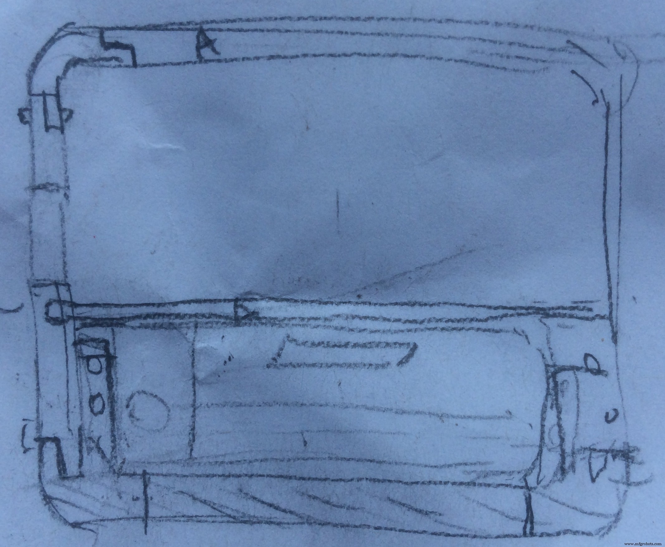
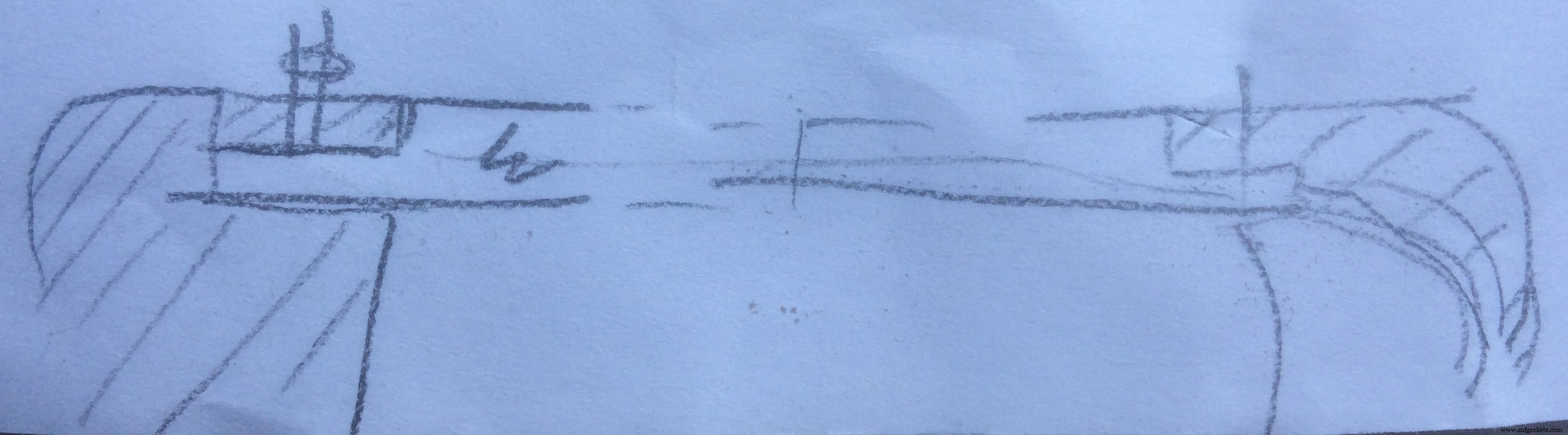
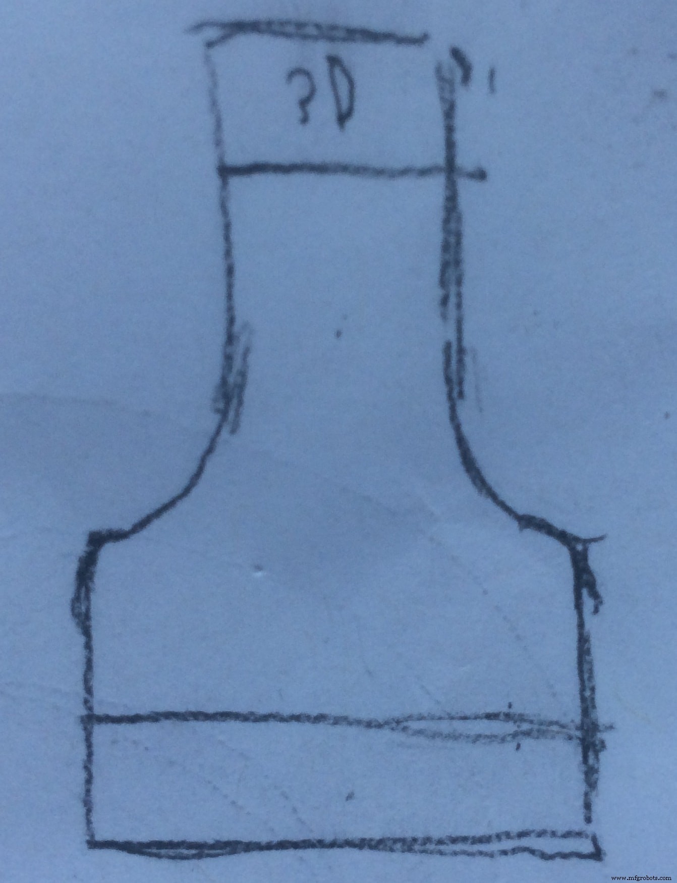
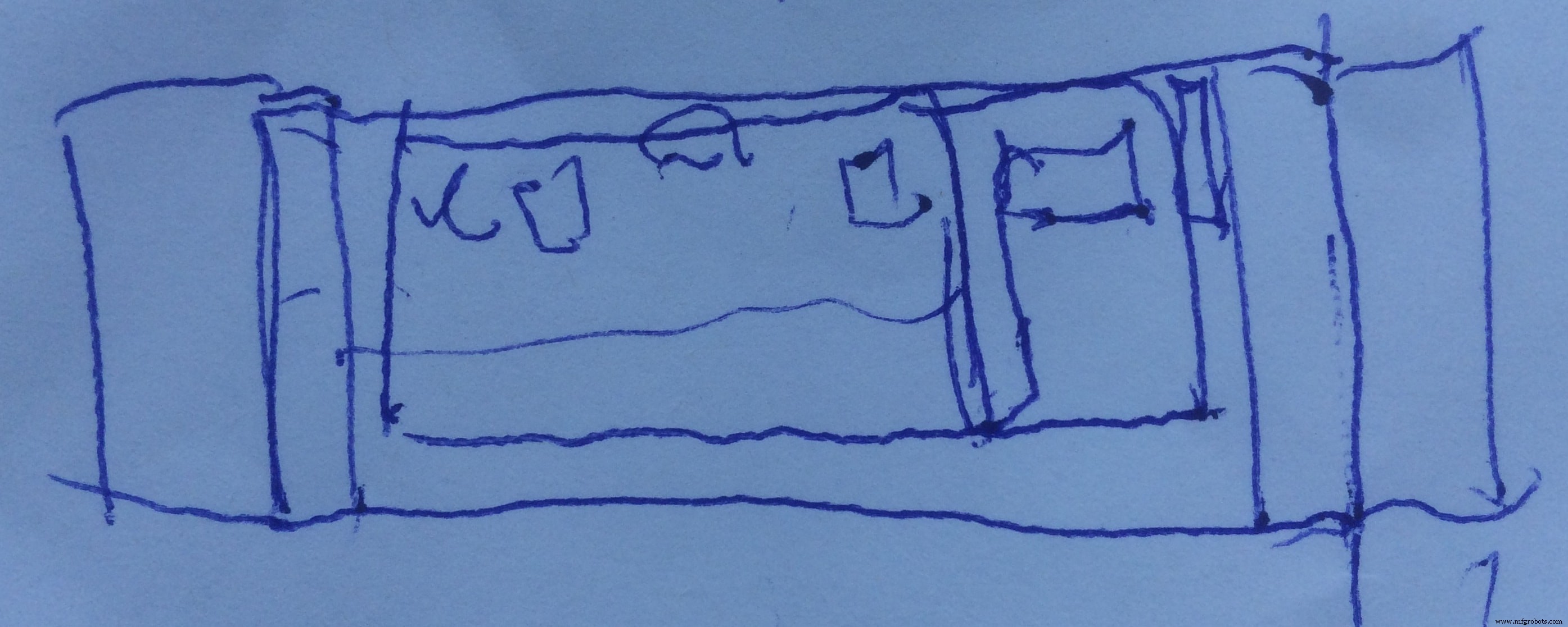
And this is the final 3D design:
My sexy ass system :D
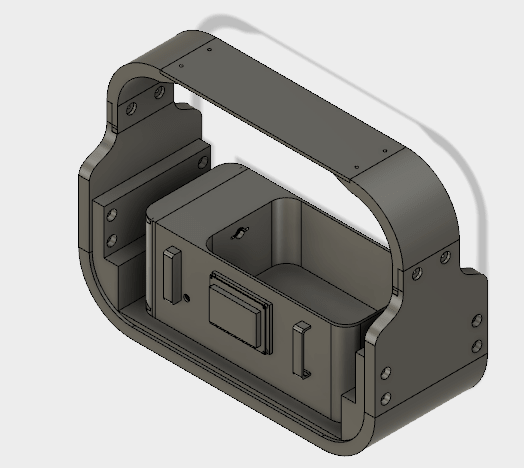
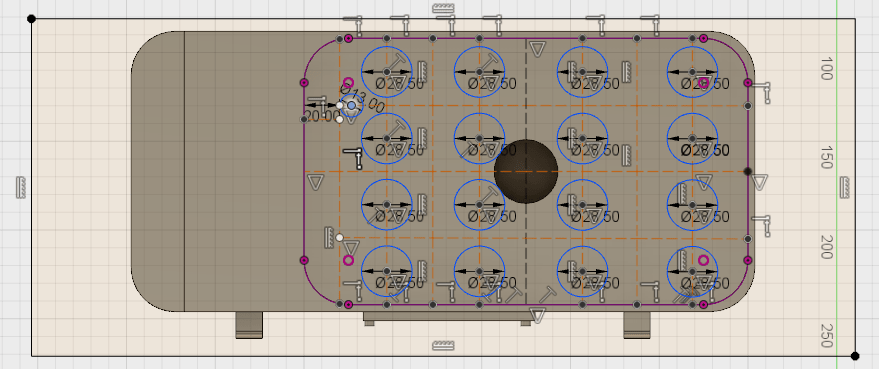
First thing which I designed was the water container . Here it is:
It incorporates several features! First, there is enough space for plants to grow, as well as in the middle I made a hole to place the Ultrasonic Atomizer. It is done because I wanted to level the fogger with the container. The thing is that the water level should be above the fogger by 2cm, so all the water which is leveled with the fogger hight, will not be used (waste)! So if I place the fogger below the container level, I have a water zero level exactly at the point where it should be, zero for the container =2cm above the fogger. In this way, all the water is used!
I also considered the hight of the container. Actually, all the dimensions of the container are measured during the experimental stage!
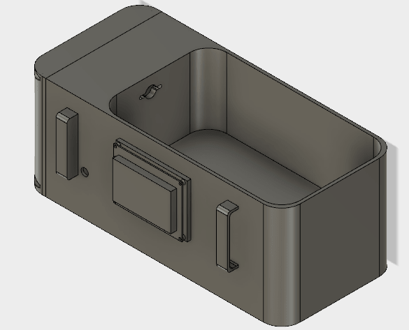
As you can see, I made a hole on the wall, which will be used for the cables from sensors placed in the water to hide into the electronics section. In the front of the container, I made the slot to attach the graphic display. I also designed some handles to easily remove the container when need!
From this perspective, you can see the electronics section. Now its opened, but I also designed a lid to close it. Inside the electronics section, I designed a hole to have access to power and program the board
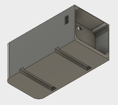
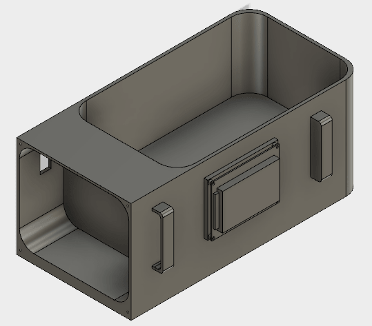
On the bottom side I designed sliders which will be attached to the rest of the system, and make it easier to remove the container when needed, it will also play a role of fixation of the container in place!
And now Let's Print It!
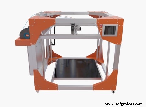
I can proudly announce that the printer which I will be using is called BigRep 3D Printer , only available in our FabLab Kamp-Lintfort. It has a capacity of one cubic meter, and provides the largest FFF build volume for professional and industrial use.
The slicing software which I use is Simplify3D , one of the most advanced slicing tools, in my opinion, with a lot of configurations and options.

I do not think that there is a right and a wrong way to print something, you just have to play with the settings until you find the best options for the specific object to print.
Because this printer is new, there are not too many testings made. So, I had to experiment with the settings, and try, try and again try...
I will show bellow the settings that I will be using for my water container print, but some of them are intuitive.
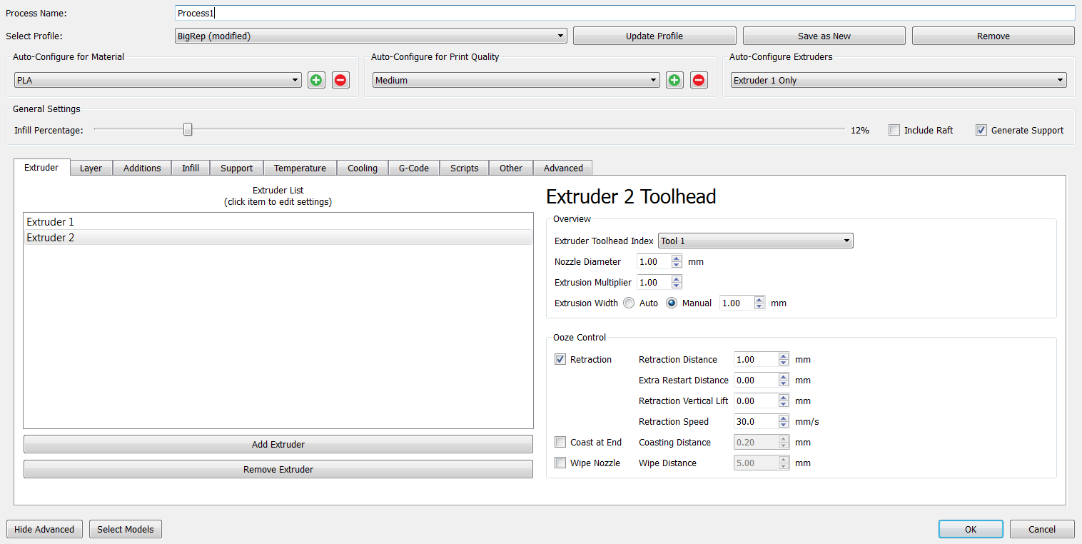
I choose the Tool1 , because the BigRep Printer has two nozzels with two different filaments, and I have to specify which nozzel I want to use, as well as the nozzle diameter and the rest of the settings.
Layer: 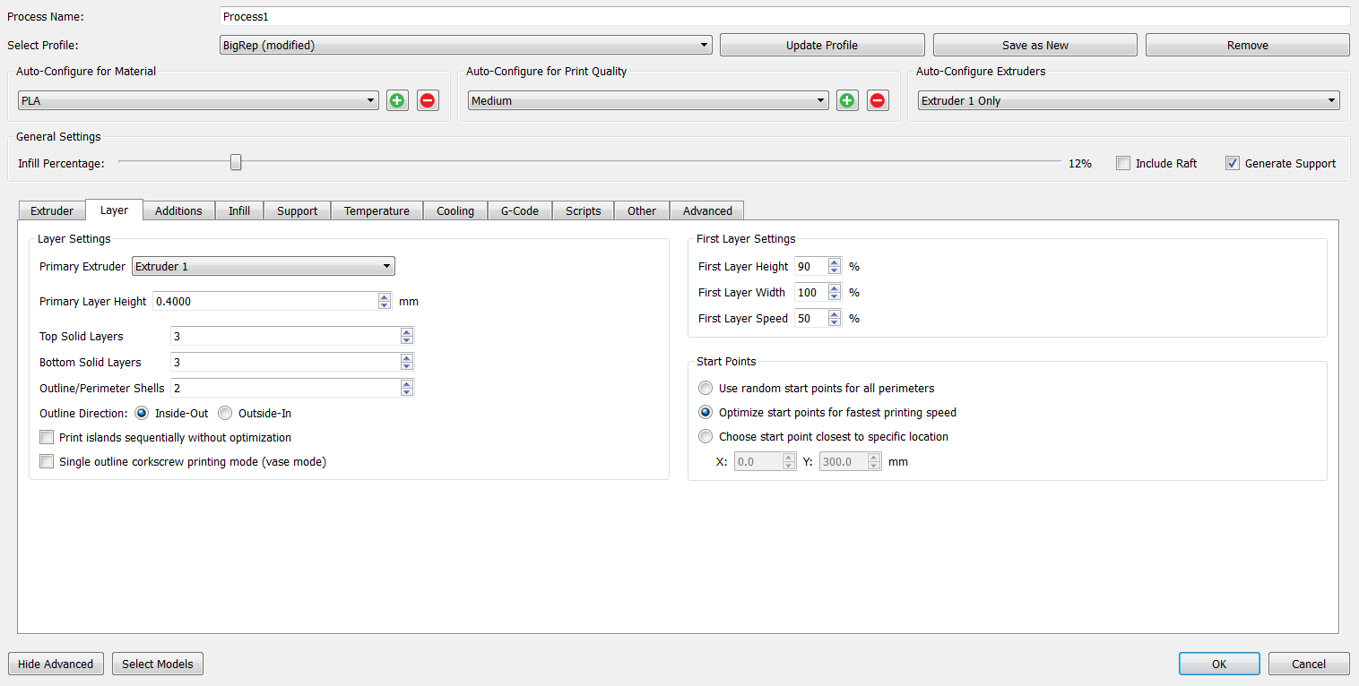
Additions: 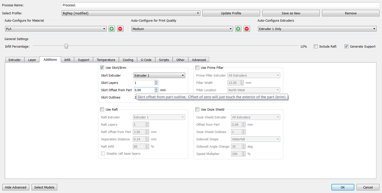
Infill: 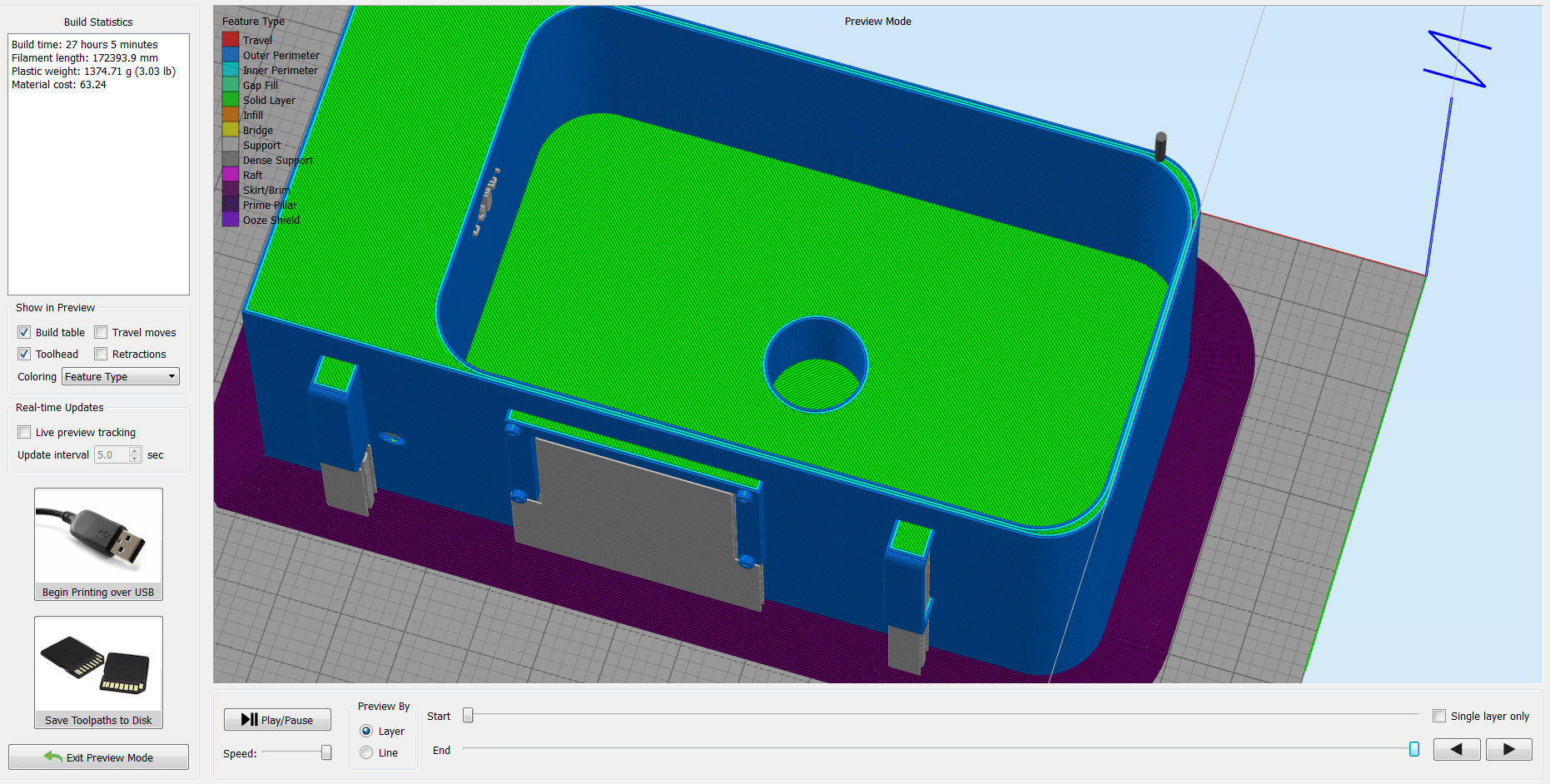
Dukungan: 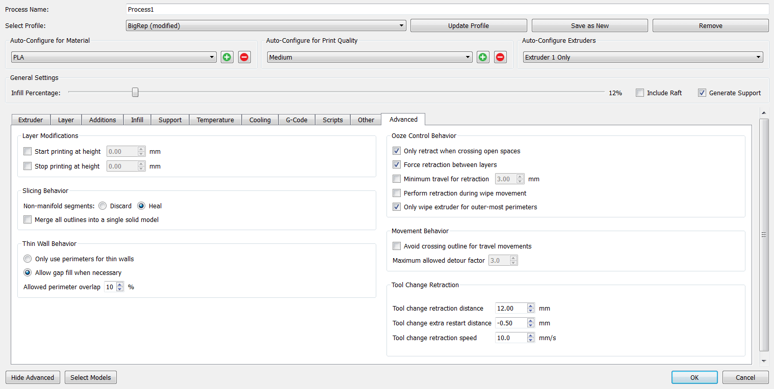
Temperature: 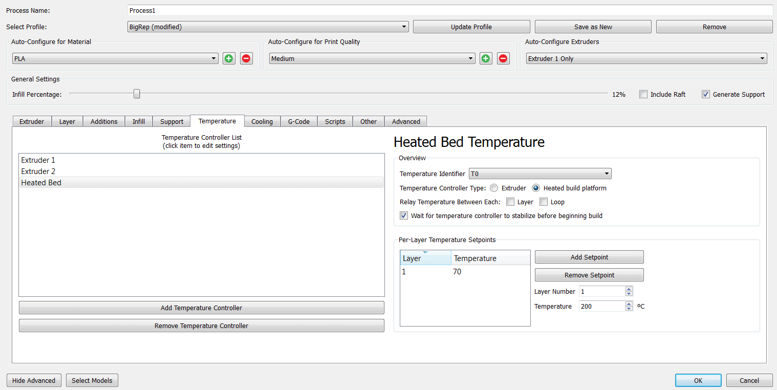
Cooling: 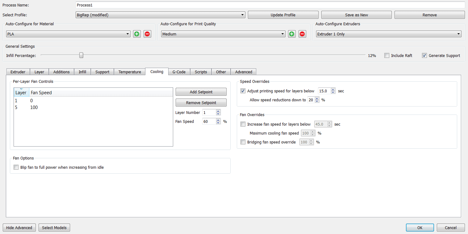
Other: 
Advanced:
These are the changes that I made, the rest of the settings I just left by default.
And then press on Prepare to Print . The software will generate the paths, and here we can check if everything is good, before sending the .gcode to the maschine.
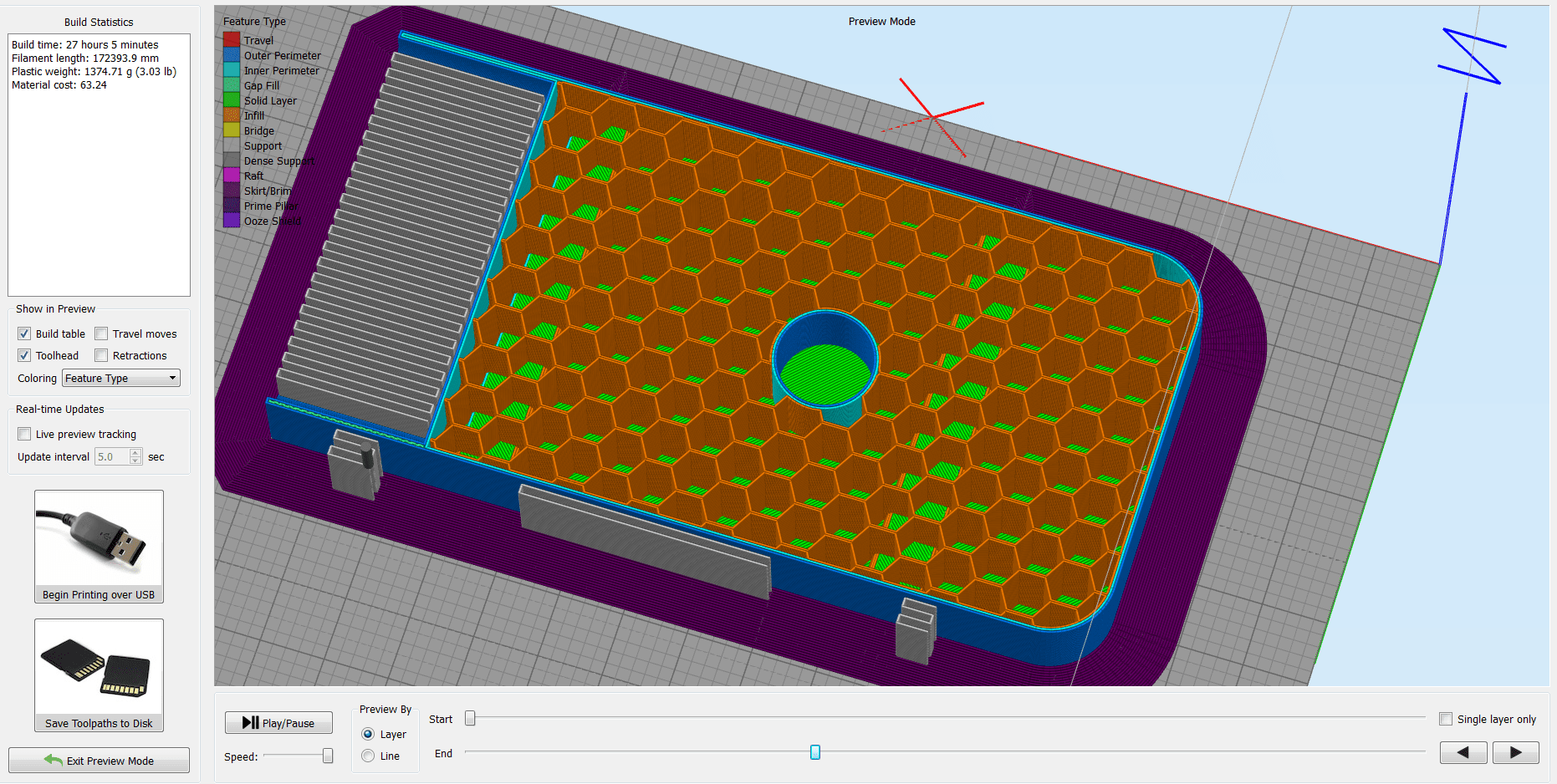
Briefly about some of the printer's settings. I used Nozzle Temperature =205 deg.C , and the Bed Temperature =70 deg.C . After I positioned the X, Y, and Z axis , and double checked all the settings, I launched the job!
This is how the raw model looks like:
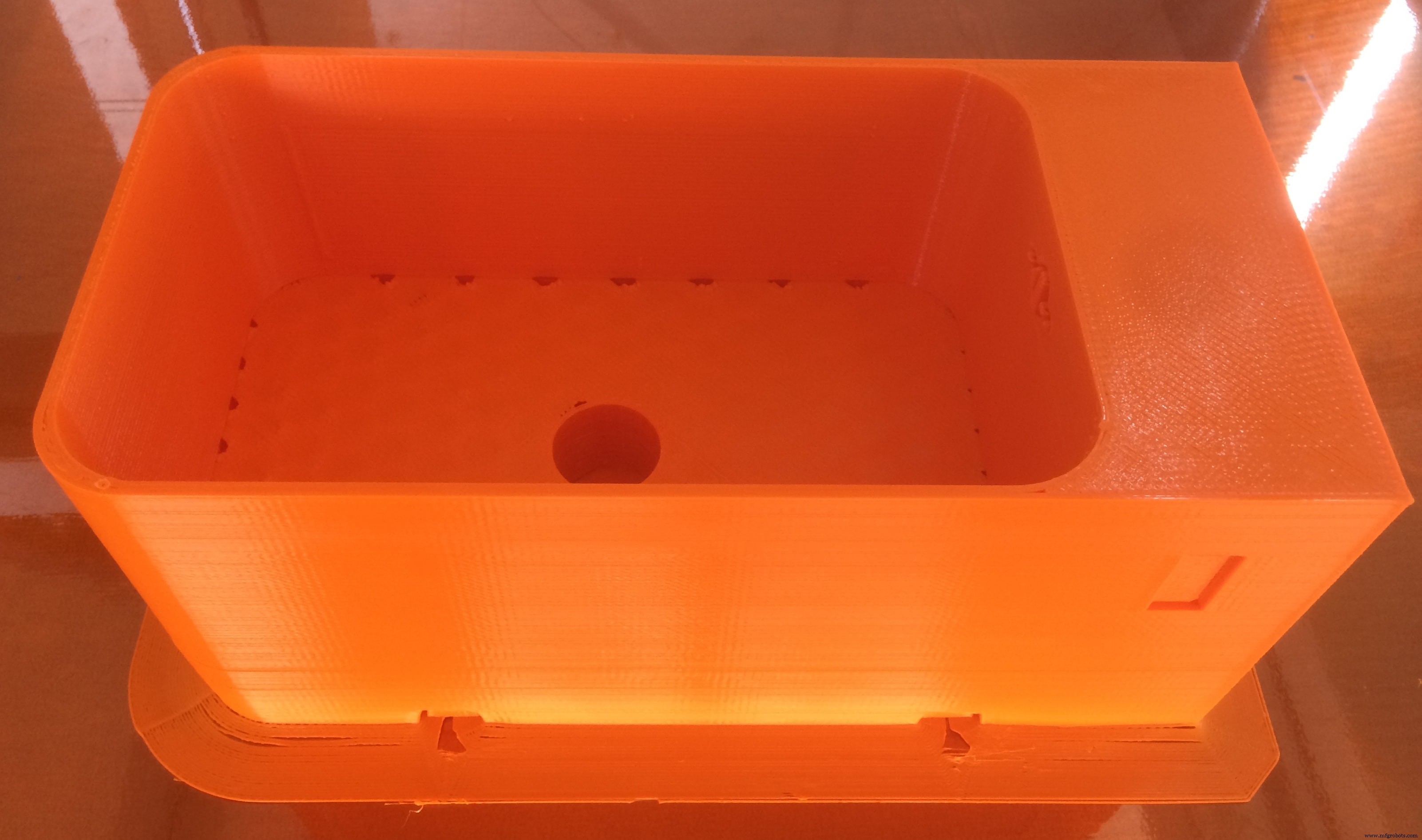
When I started removing the support and cleaning the model, I realized that this is a BIG pain in the ASS :D
As you can notice, the settings which I used are not really perfect, because the container has some big holes next to the edges. I had in my mind to waterproof it anyway, you can see how I did it in the Moulding &Casting section!
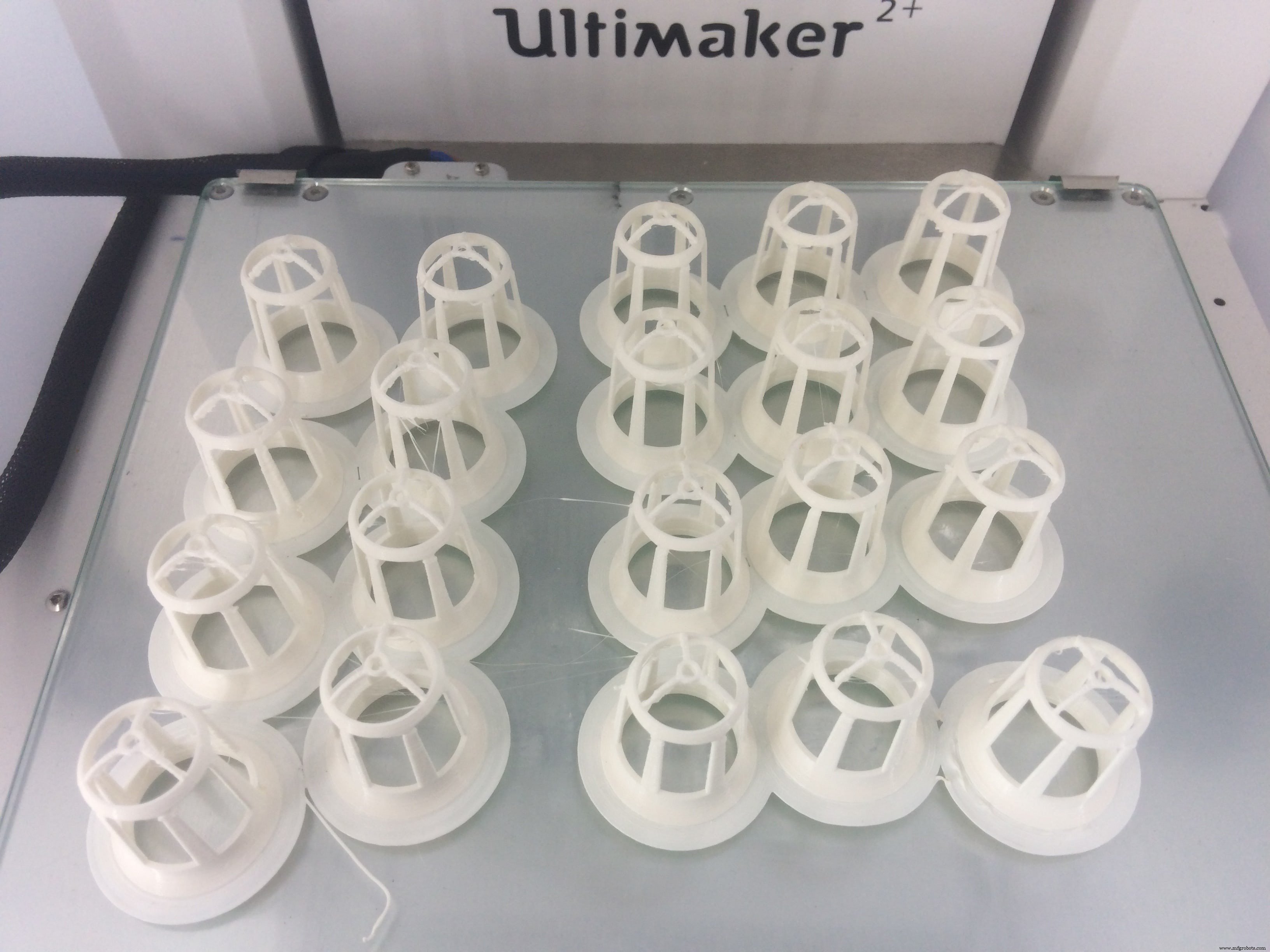
The next 3D printed part was the Net Pot . This is a cup which is designed to hold the seeds in the growing medium. More detailes about the first version of them you can see during my Computer-Aided Design week
This time I will improve the design a bit based on the observations that I made during the experimental stage. The main difference is the size of the empty space, which is increased a lot, to give an easier access for the fog to pass in, and for the roots to go through
So I just modified the old design, and added one more thing!
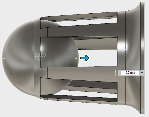
I made a slight fillet on the top part, to make the transition smoother. I also added a ball on the bottom, and used the Move command to move it a bit inside, and leave on the bottom around 2-3mm structure width
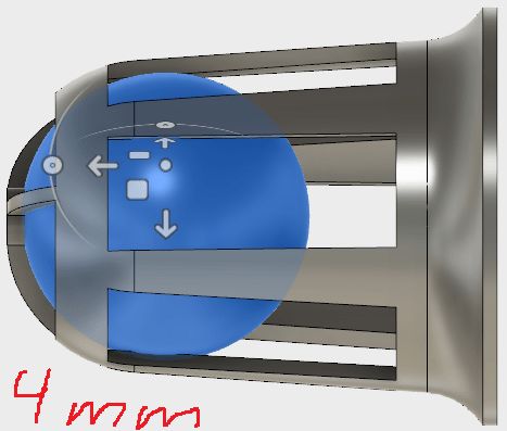
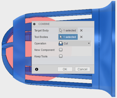
After I used the boolean substraction or Combine function, and I get this nice curviture at the bottom!
Now let's print it!
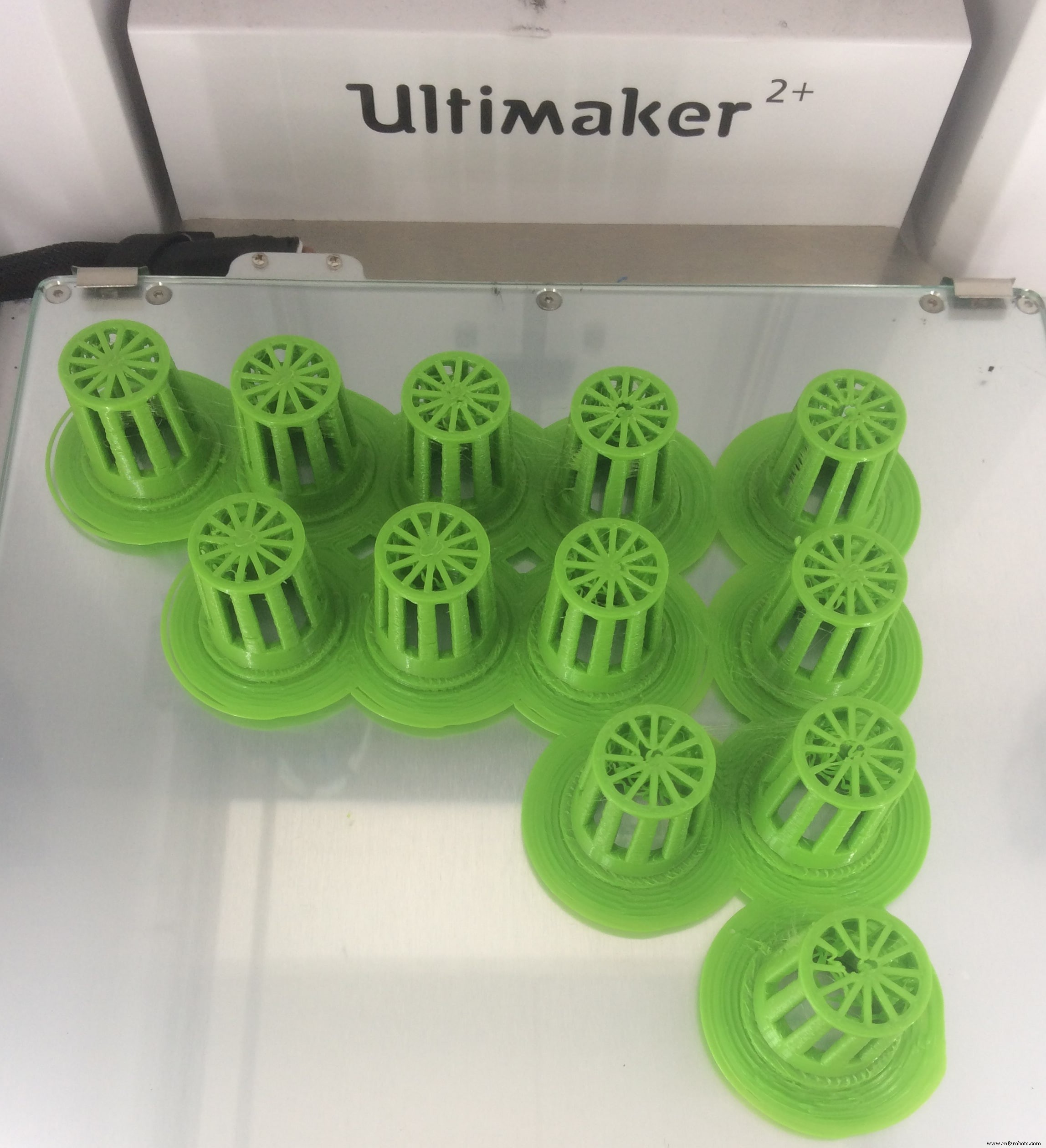
The 3D printer which I used is Ultimaker 2+ . To slice my 3D model, I will use, a very nice software, with an easy interface, and also functional. The material that I am using is PLA filament

After I import my .stl file, these are the settings that I am using:
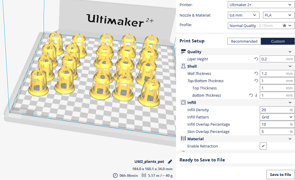
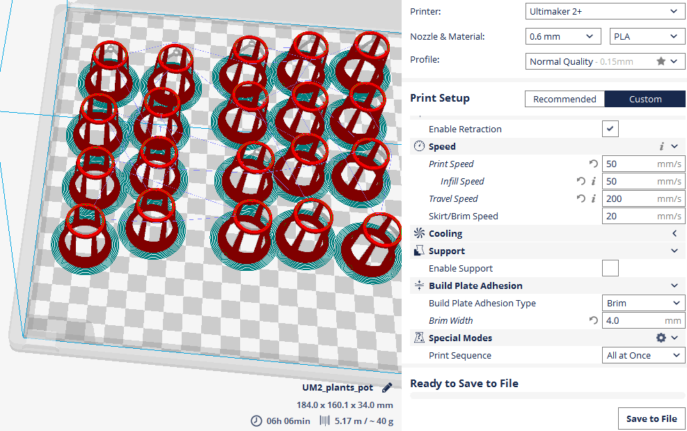
Here it is my little army :D
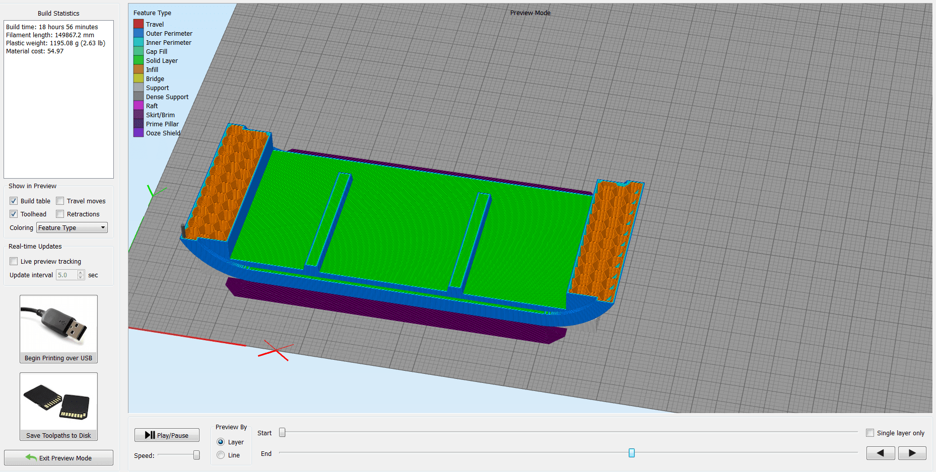
From the final design of the system, I decided to also 3D print the bottom part. Its a big piece, and I will use the BigRap as well for this.
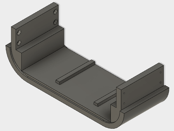
I wouldn't say that there is anything new about this, because I used the same settings as I used for the water container , and more or less the rest is the same
Here is the preview of the print:
Another thing which I 3D printed are the rounded corners on the top side of the system. I used the Ultimaker for this, and used the following settings:
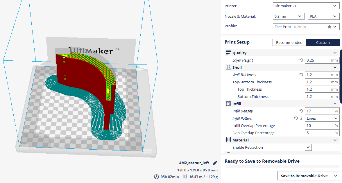
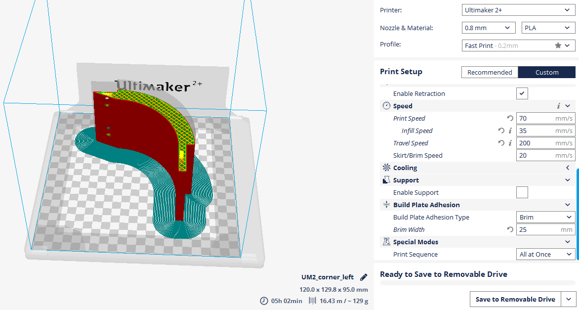
The trick here was to achieve maximum smoothness on the surface, and I think I got a pretty good result:

Download Files:
GIY System Design (.f3d)
Net Pot Design (.f3d)
2D Design &Laser Cutting
I used the Laser cutting technique to cut acrylic parts which will cover all the inside part of the system, and give it a finished look!
I actually did not design the parts again, I just exported the already created sketches from Fusion 360 as .dxf files . After I exported the file, I used to edit the design before importing it into the lasercut machine

This is how the sketch looks in Fusion360:
Looks like a big mess, but the good part is that everything is parametric! It looks messy because I had to align everything into the right position, and keep the stuff parametric in case I have to make a change later
This is how the final sketch looks in Rhino before lasercutting:
I decided to use a green acrylic piece because it gives an organic look, and combines well with the green plants
For the front and the back cover, I decided to use white color. Its all about the taste, this is the way I see it, and this is how I like it.
The front and the back cover are very similar, have the same dimensions, except the inside cuts! The front cover has the hole for the LCD Display, here it is:
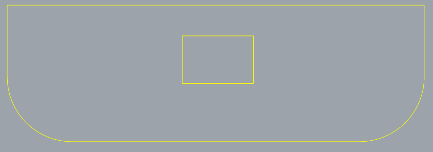
For the back cover, I want to make a hole to have access to power and program the board! This is how it looks:
Another lasercutted piece is on the top! I decided to use a transparent acrylic part, in order for the light to go through! I also designed some additional cuts, to decrease the weight, and give more space for the light to pass! I also measured the width of the RGB LED stripes, and will attach them in a way that there is enough room for the sunlight as well as artificial light!

I finished with the design, and now Let's Laser Cut!
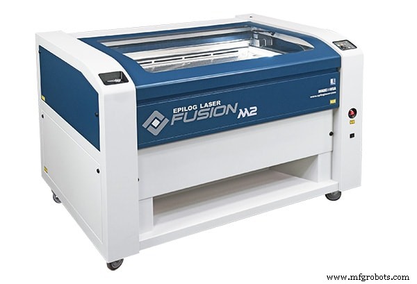
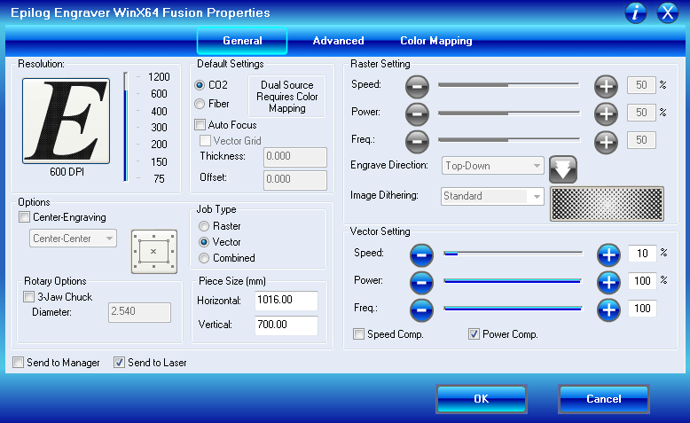
The Laser Cutter that we are using here in FabLab is Epilog Fusion 60Watt, a CO2 lasercutter with a working area of 1016 x 711 mm. It can cut and ingrave materials like wood, cardboard, acrylic or other engineered plastics.
Because I used the same material for all the pieces, plexiglass 5mm , I used the same settings for all of them!
Download Files:
Front / Back Cover (.dxf)
Plant Holder (.dxf)
LED Light Holder (.dxf)
CNC Milling
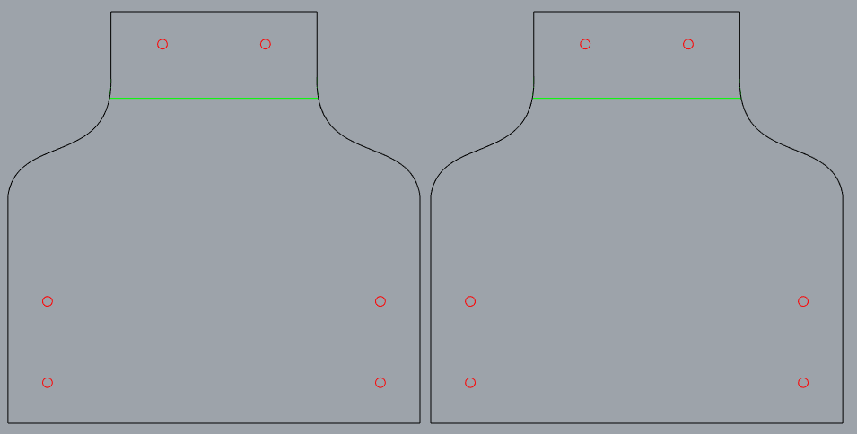
Because I wanted to integrate in my system all the skills and techniques that I learned, I also have a piece of structure to CNC mill. I did not design it again, but I exported the .dxf file from Fusion360 sketch!
To cut my design, I will be using the big CNC monster.
A CNC (computer numerically controlled) is a machine that uses a cutting bit that rotates at a very high speed to remove material from a part.
The machine reads a pre‐programed computer file telling it where and how to cut, usually .GCode mengajukan. A cutting bit is rotated at a very high RPM by a spindle motor, which can move the bit up and down. This mechanism is moved left, right, front, and back by a cross arm. The machine is therefore known as a three‐axis router because it can move on the X, Y &Z axis. The machine can do two dimensional cutouts and etching, as well as three‐dimensional relief work.
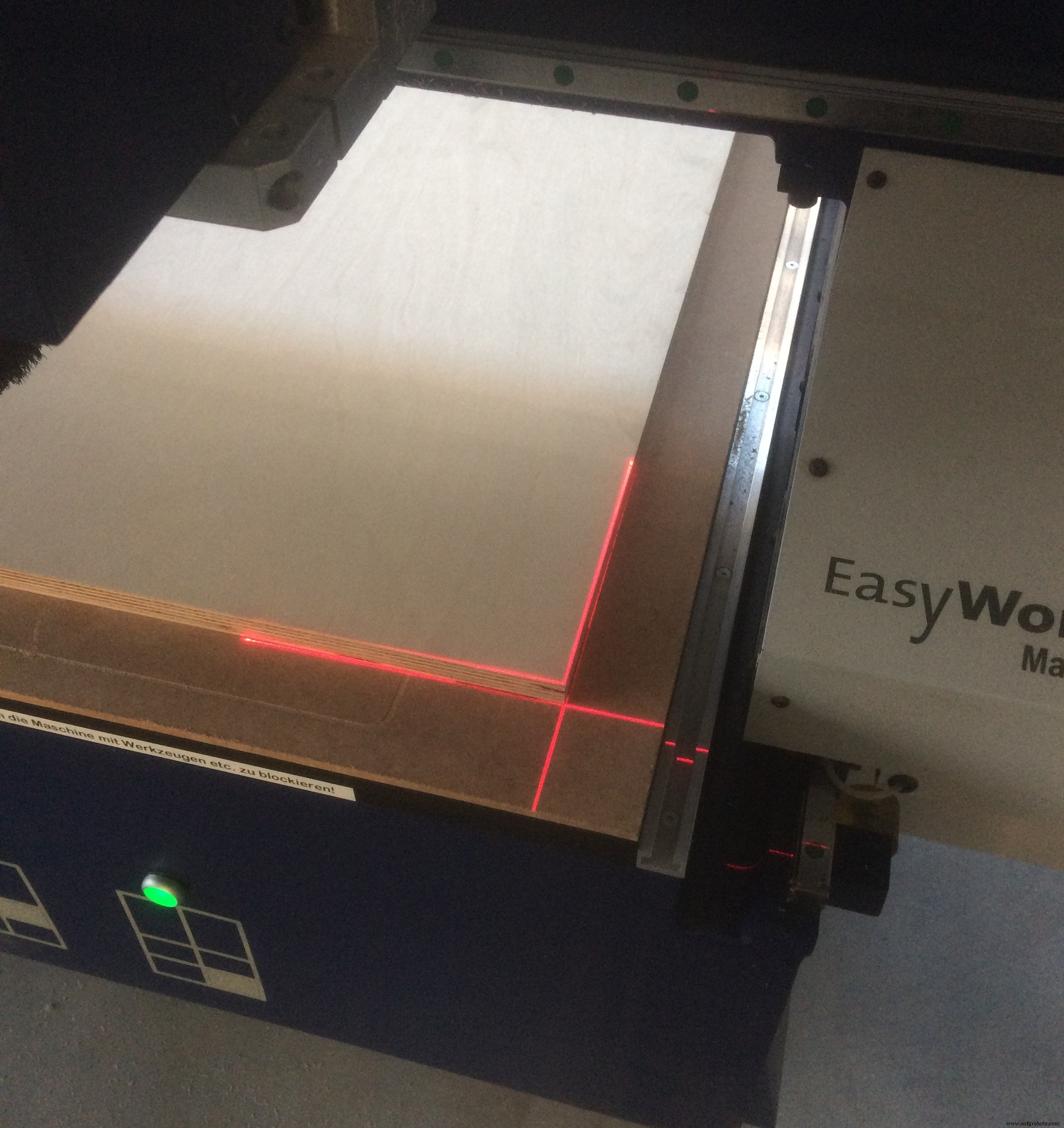
In FabLab Kamp-Lintfort we have a CNC portal milling machine by e(sign:Easy Worker MasterPro 2513.
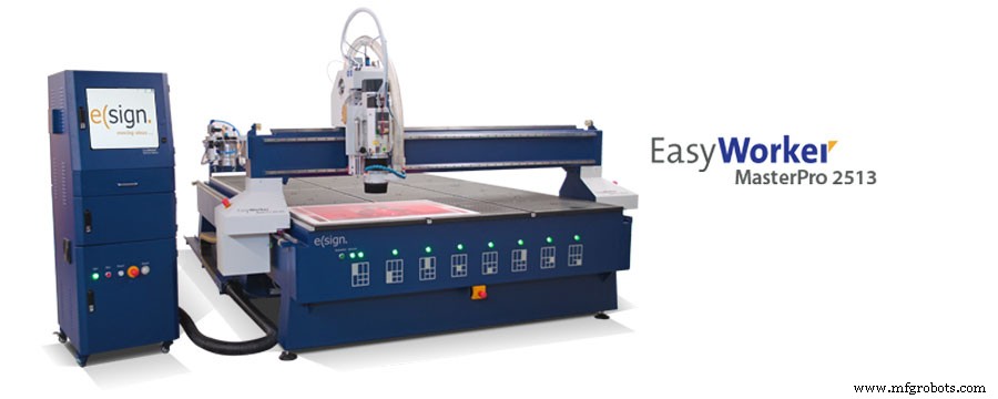
It’s working area is 2600 x 1400 x 300mm and it comes with a vacuum table. We primarily use it for wood milling but with its HSD Spindel (3.9KW; 24.000U/min) it is also capable to mill metals easily.
The material which I will be using is 18mm Plywood
At first, I place the wood sheet on the CNC bed, and after I aligned it, switch on the vacuum. After I exported the .dxf file, I used to edit the design before importing it into the machine CAM software.
First, I have to HOME the machine!
To set the X, Y and Z Zero Positions, I home the machine by pressing the home button in the software (or on the remote control).
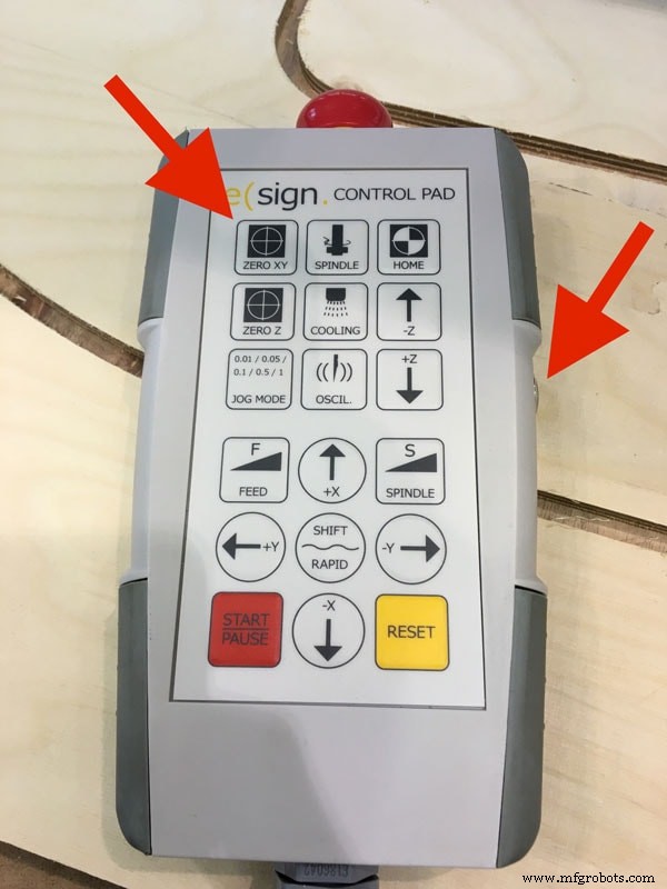
At first, I can set my zero X and Y roughly aligned to one of the corners of the bed. We also tried to use the laser for this, but all the time when simulating the process, it was showing collisions, because the zero was going out of the working area
Now I have to find the Z axis, which I do using the special tool which comes with the machine:
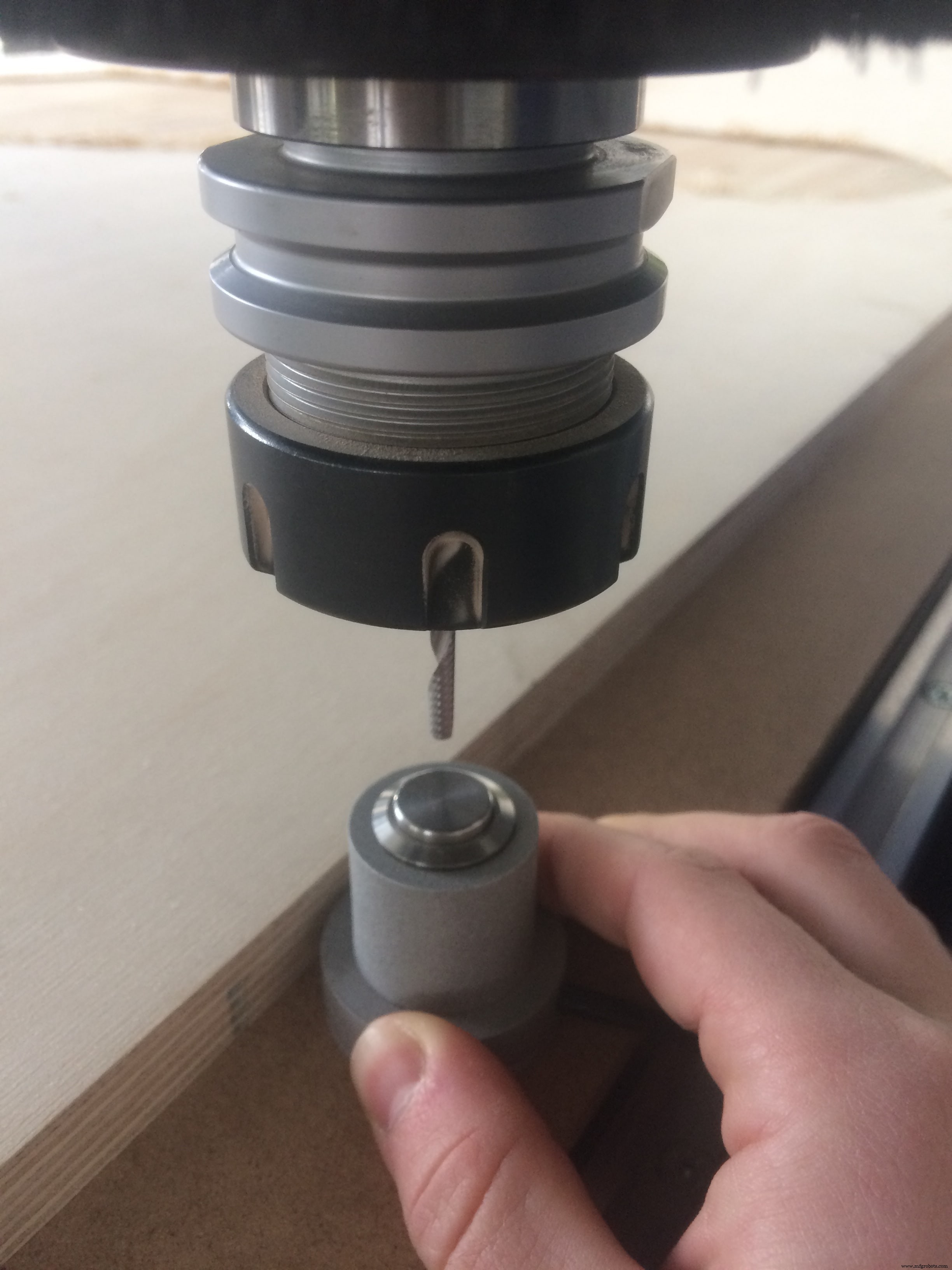
Important thing is to place it on the bed of the machine!
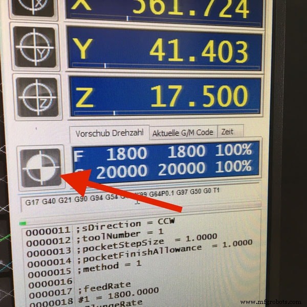
Now I can launch the first job, which is making the engraving. These are the settings which I used:
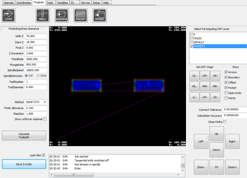
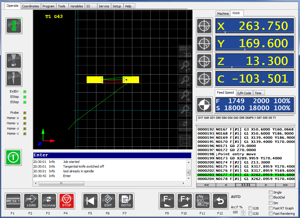
I press Calculate Toolpath to simulate the job and make sure that there are no collisions! After I save the .GCode , and launch the job, I get this window:
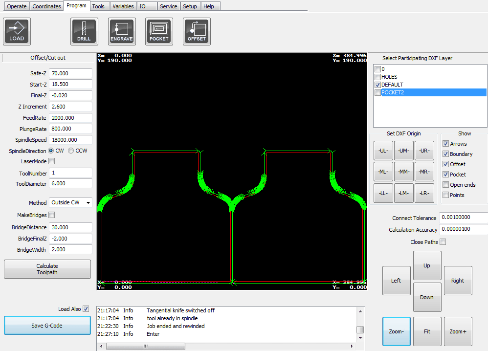
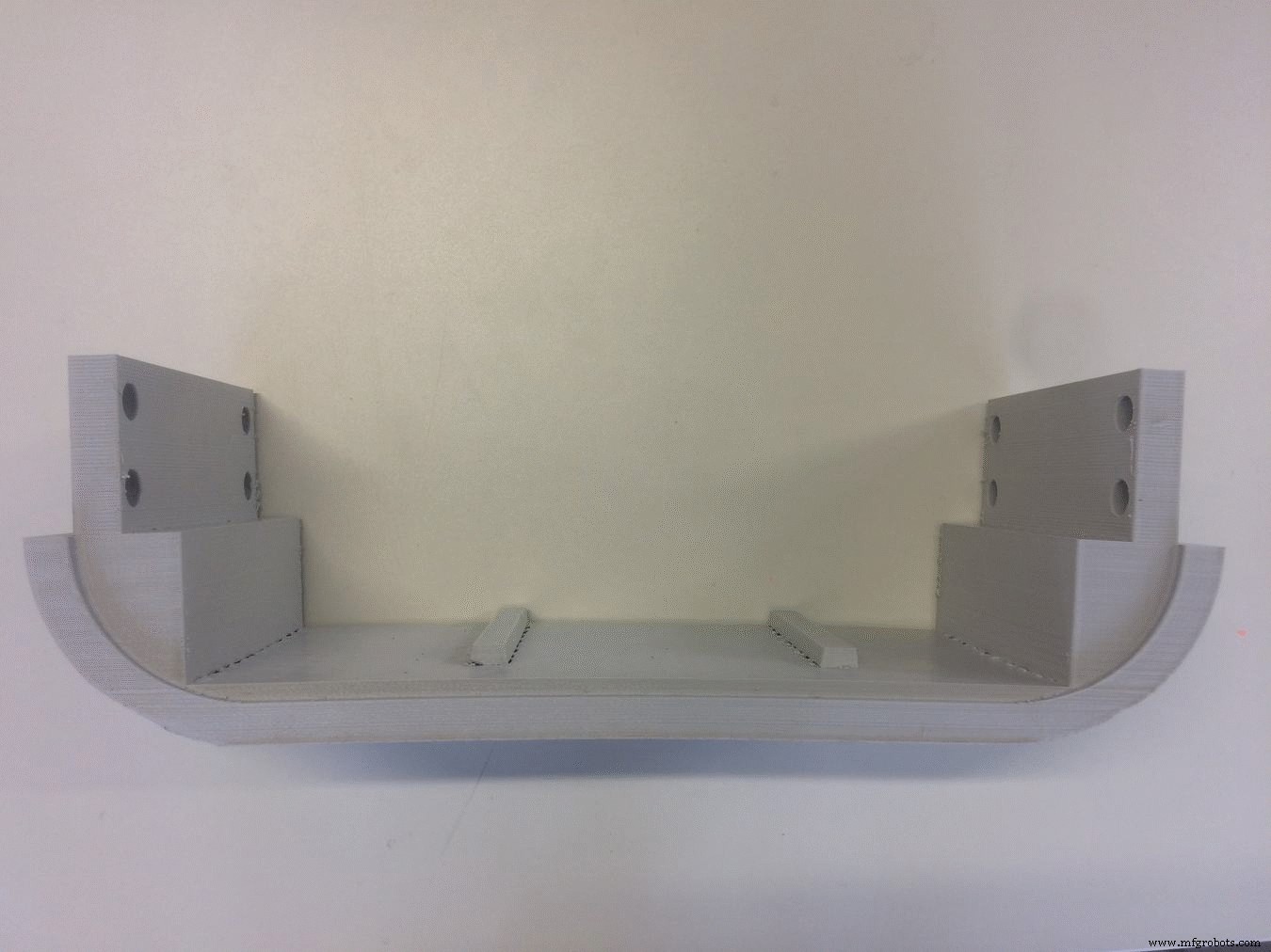
Now I can launch the outside cut:

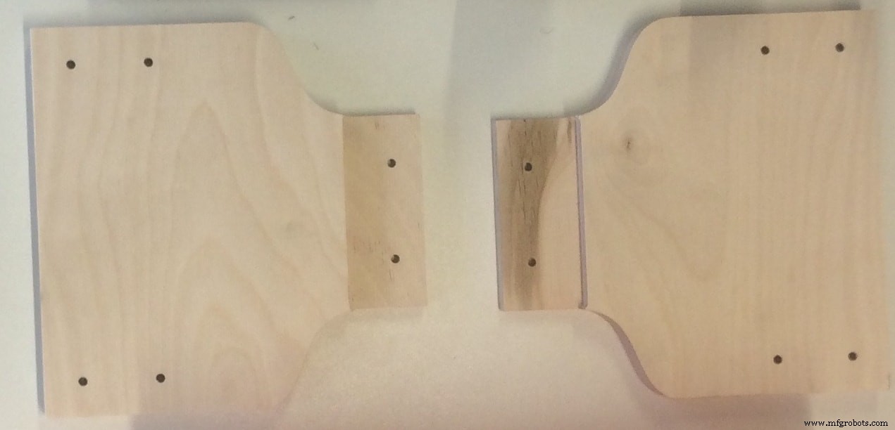
This is what I get after the job is done:
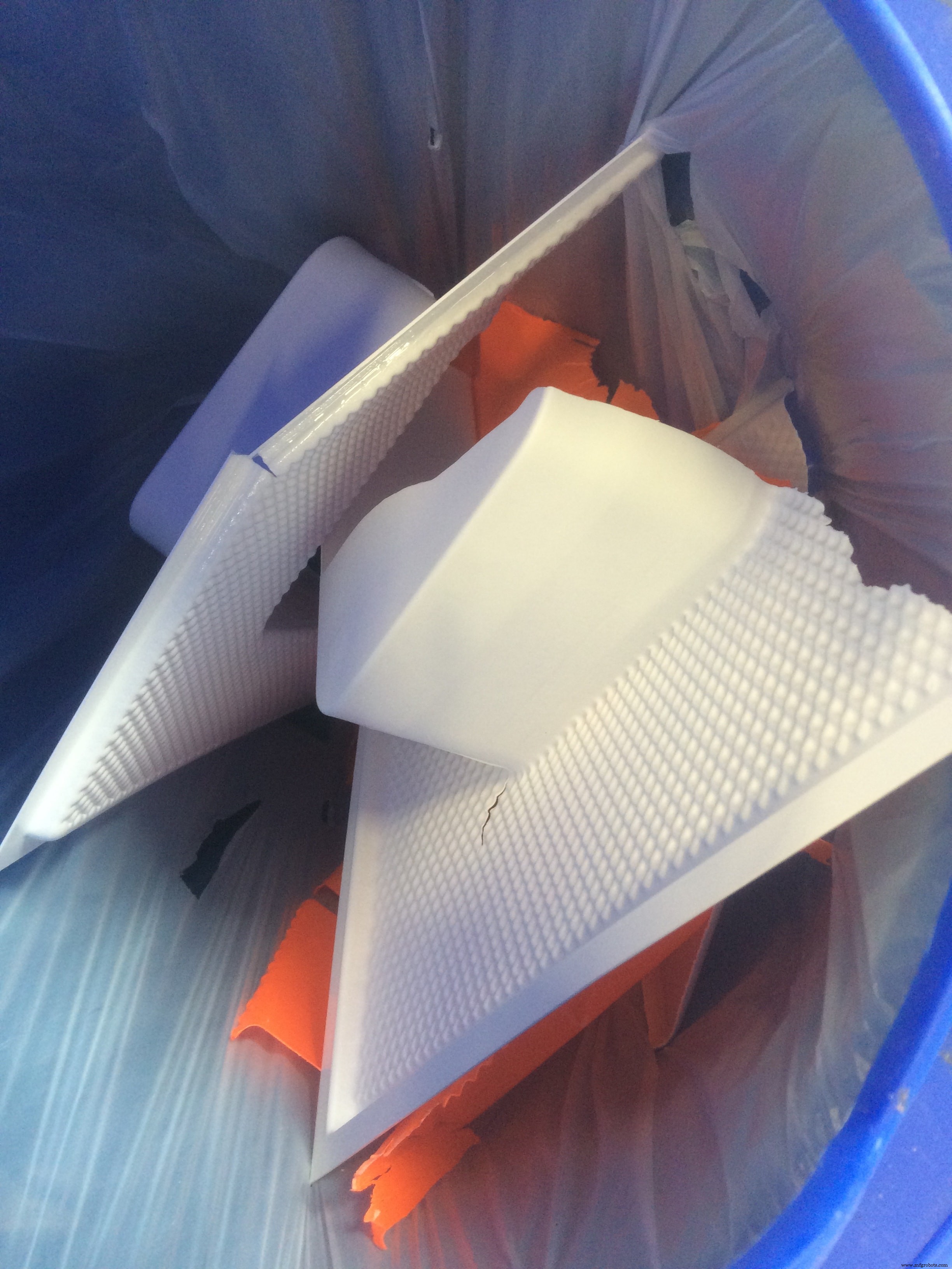
Another piece which I had to mill is used for the Moulding &Casting section!
I prepared the mould to waterproof my water container. Here is the design:

There is nothing new about this. I used exactly the same settings as above. The only thing is the material thickness was 10mm wood , and I had to cut 7 pieces, to glue them together later and prepare my mould!
Download Files:
Structure Walls (.dxf)
Mould (.dxf)
Moulding &Casting
I used this technique in order to prepare a water container, to waterproof my existing container! I see it as a thin layer of material (a smaller container) which can be easily removable!
This is the result from the previous section CNC Milling
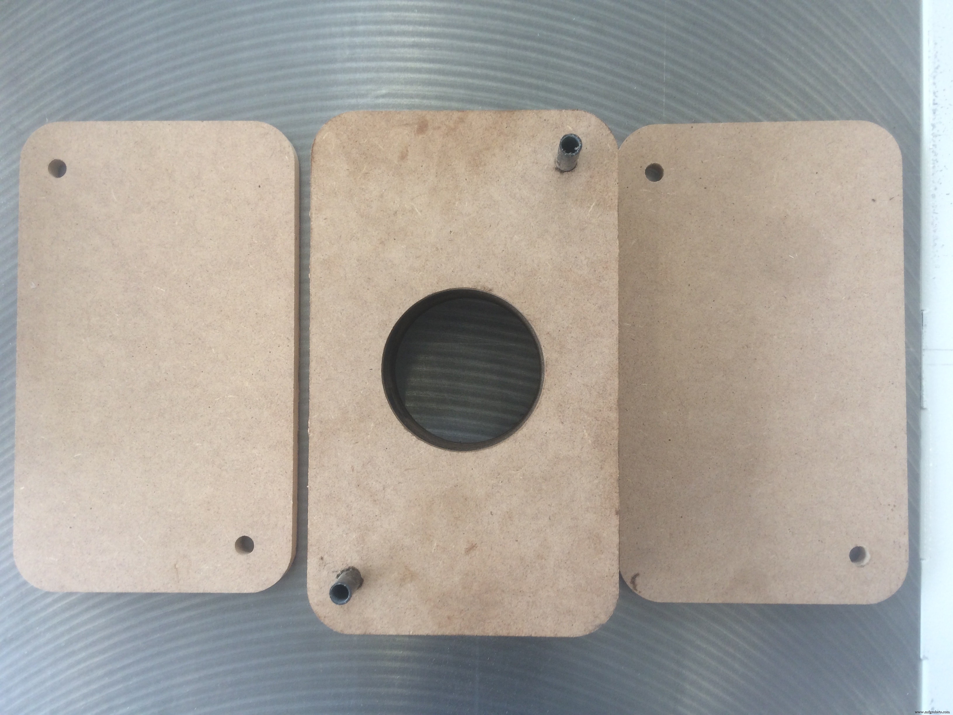
I cut 7 identical pieces, and aligned them using the reference holes! I also cut a big hole in the middle of 5 bottom pieces , in order to place the air pump inside, and easily remove the cast later.
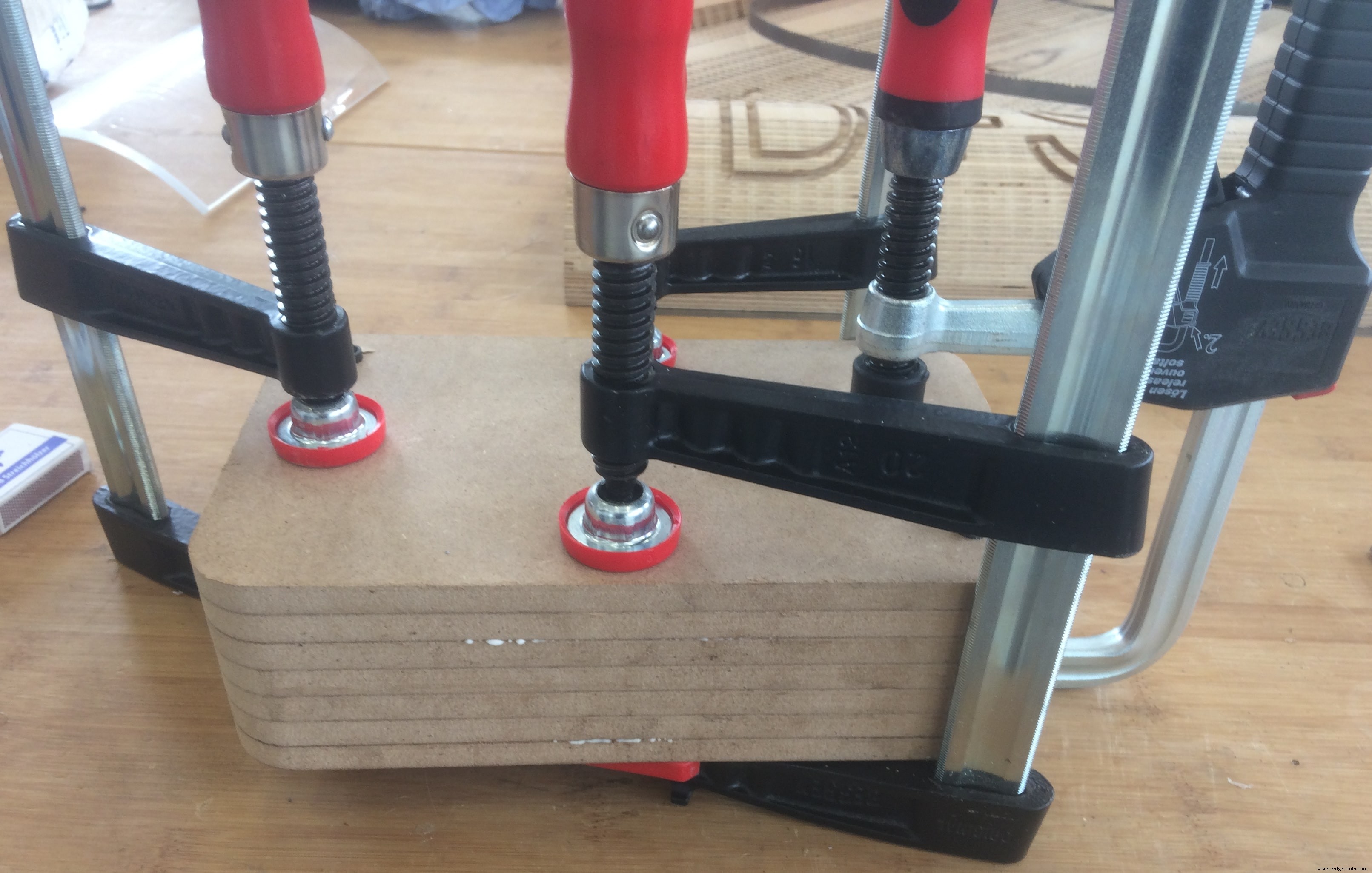
After I glued all the pieces together, and fixed them, this is how it looks:
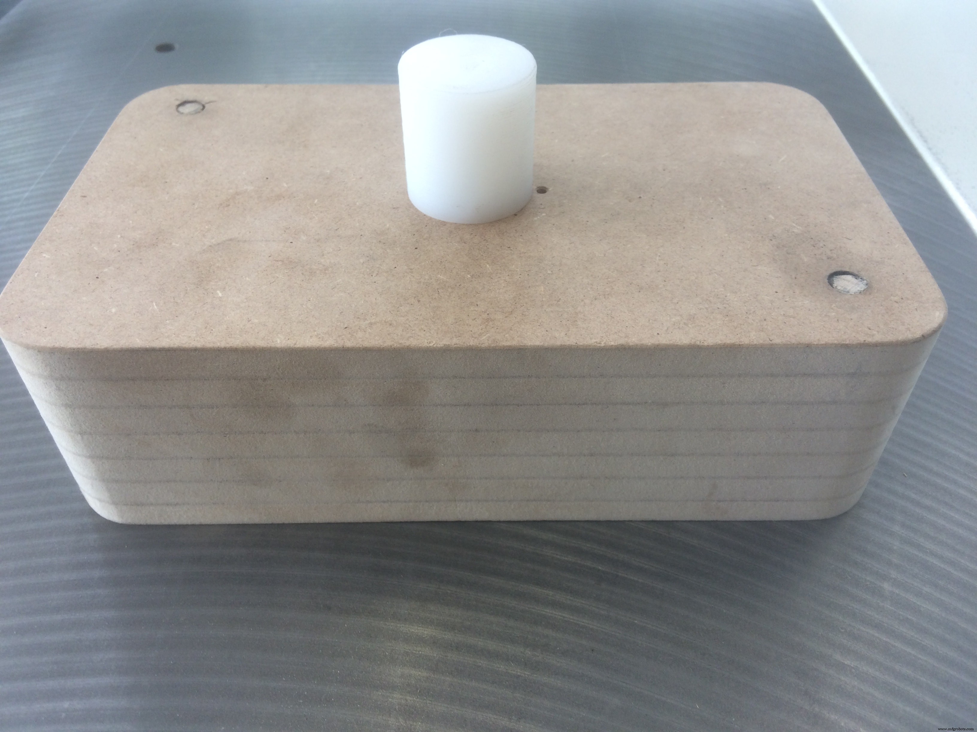
While waiting for the glue to dry out, I prepared a little plastic "thing" (do not know how to call it :D) for the pump. The idea is to be able to screw it on my mould, and remove it whenever I want!
When the mould is ready, this is how it looks:
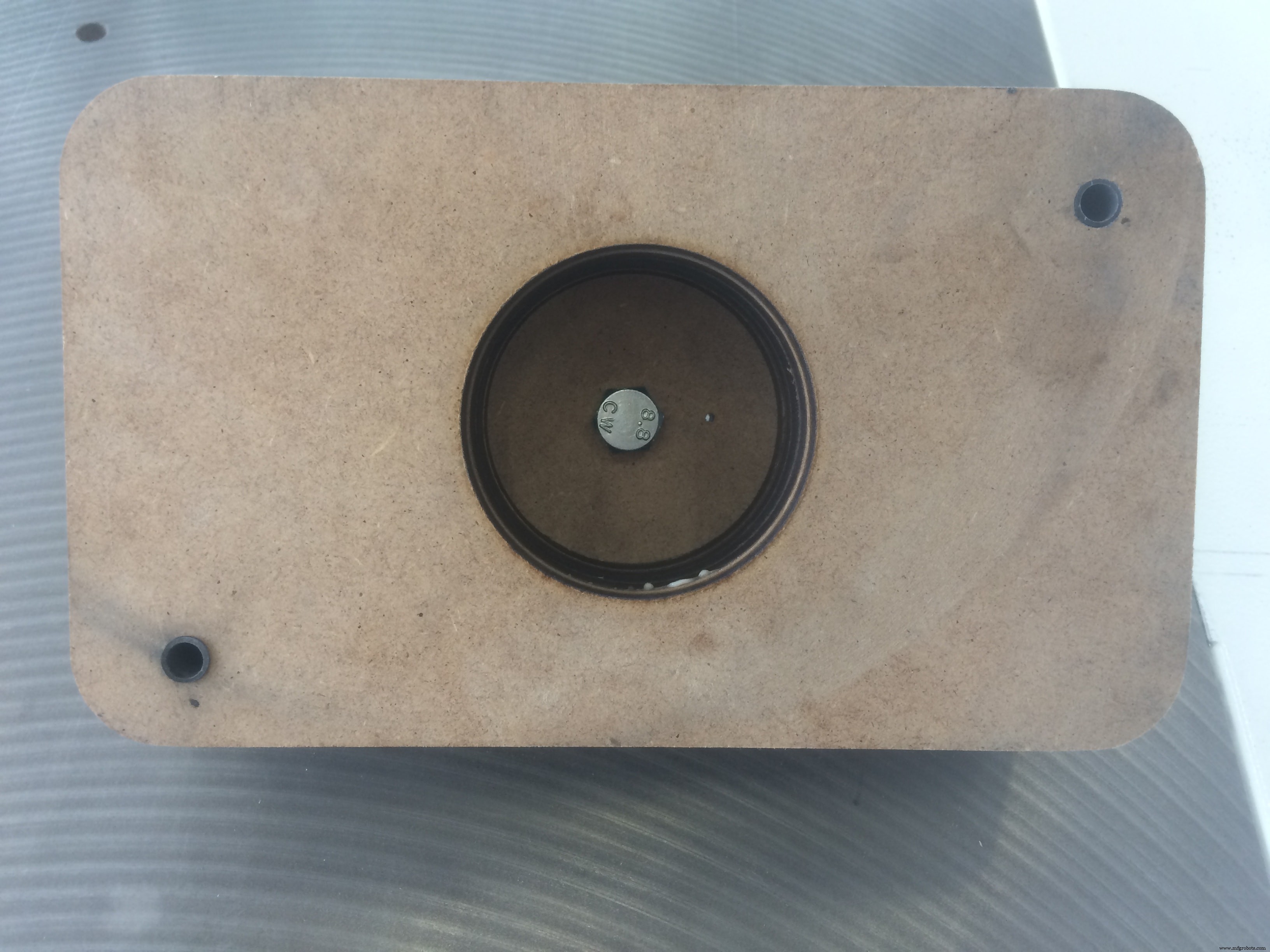
And the back side:
I am ready to vacuum cast!
I used a vacuum machine available in our FabLab Kamp-Lintfort called Formech – Manual Vacuum Forming Machine
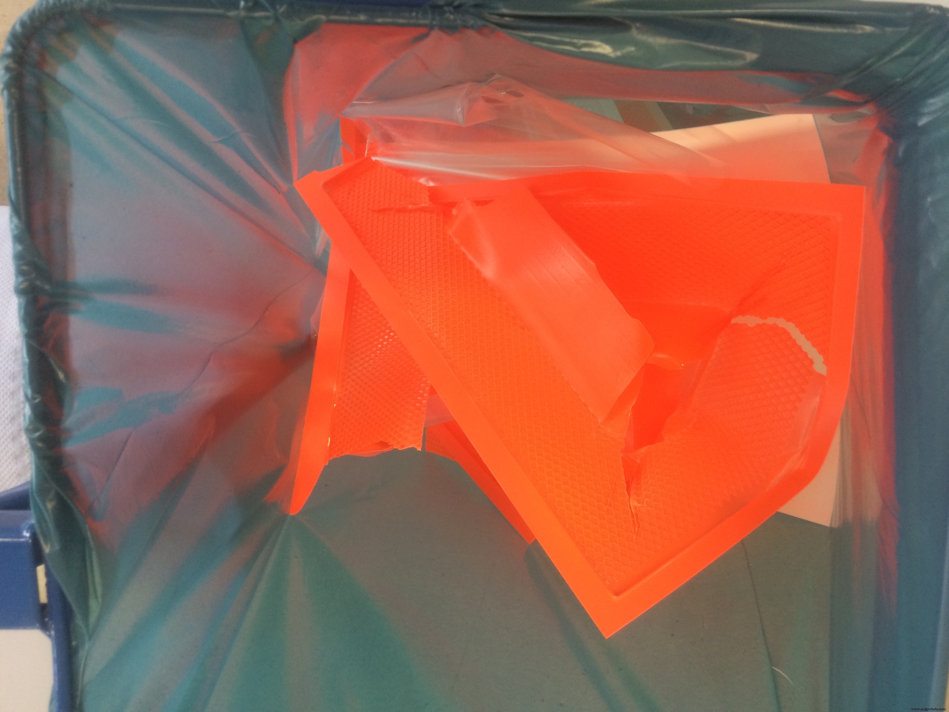
The thing is that I tried to do it many times, and all the time I could not remove the mould without breaking the cast! After several hours of trials, I came up with a solution! First, I vacuum casted one thin layer of material, and without removing it, I will cast the actual container on top of it. The first thin layer is slippery, and If I spray it with silicon, it will allow me to remove the mould way easier
After I let the silicon to dry a bit, I can cast the actual layer!
And here we are!!!
A hero shot for those who may thing that it was easy
Putting All Together
Now, let's put everything together! I will start by assembling the structure. Put next to me all the necessary tools:
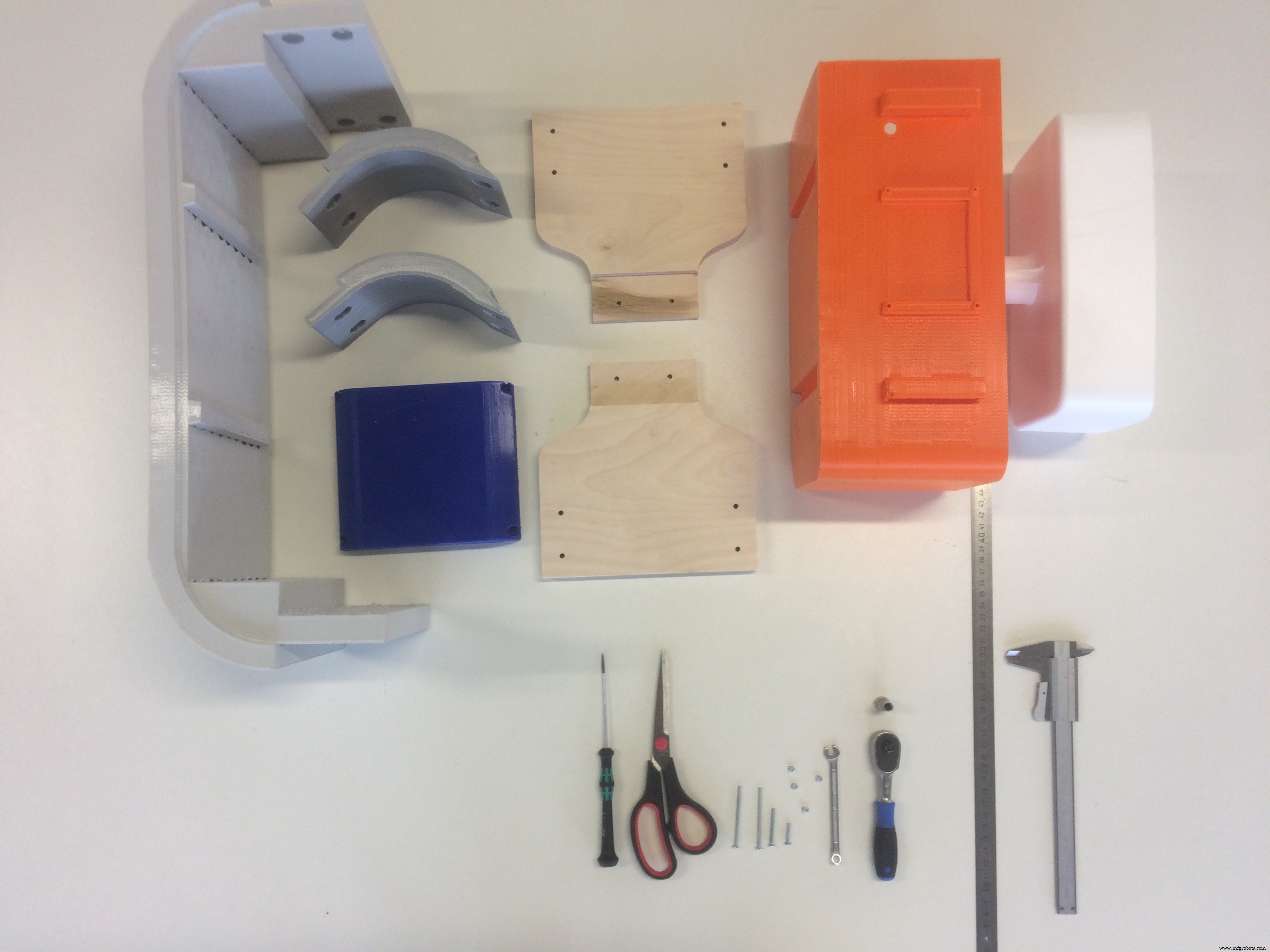
A short animation of the process:
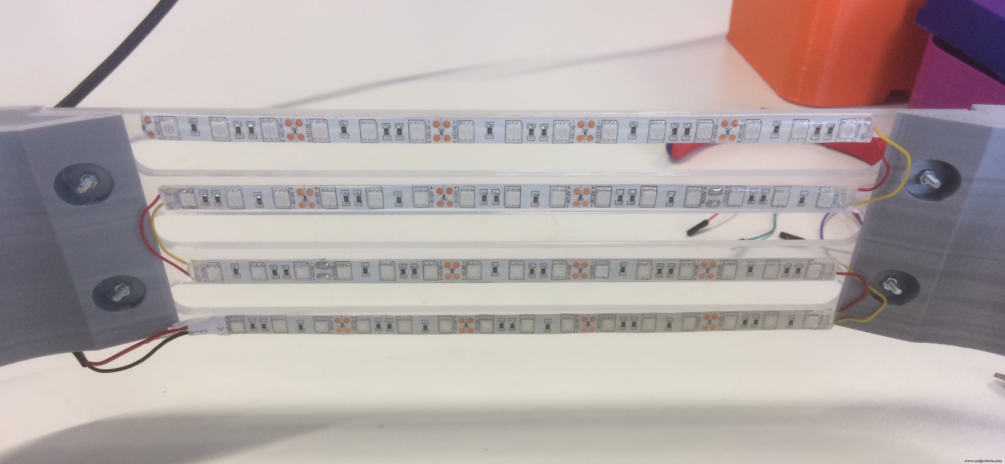
To assemble the lights, I cut the RGB LED stripes into 4 pieces (I measured the length in advance), and soldered them accordingly!
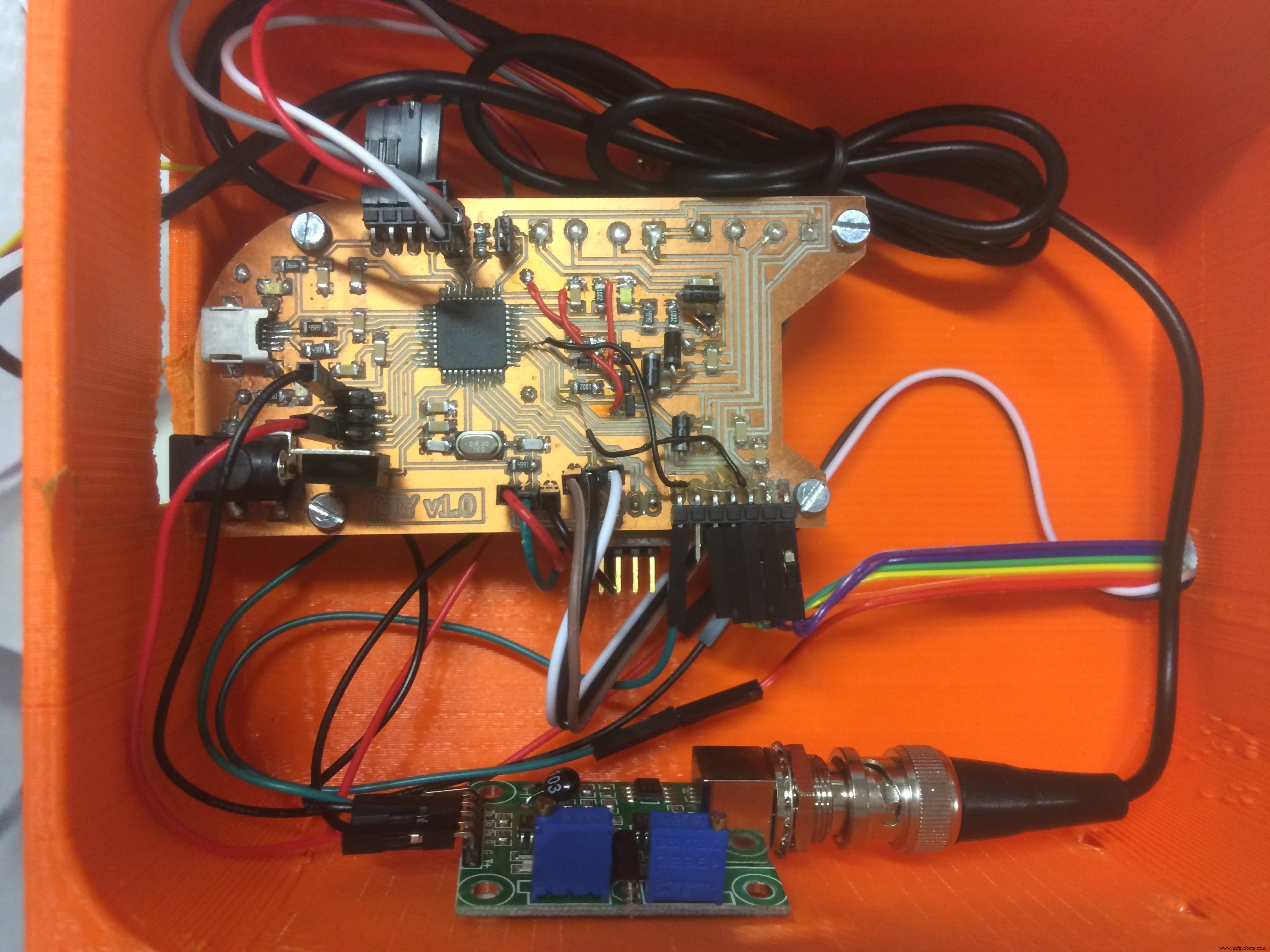
After I connected all the sensors, and managed the wiring, I fixed the board in the electronics section
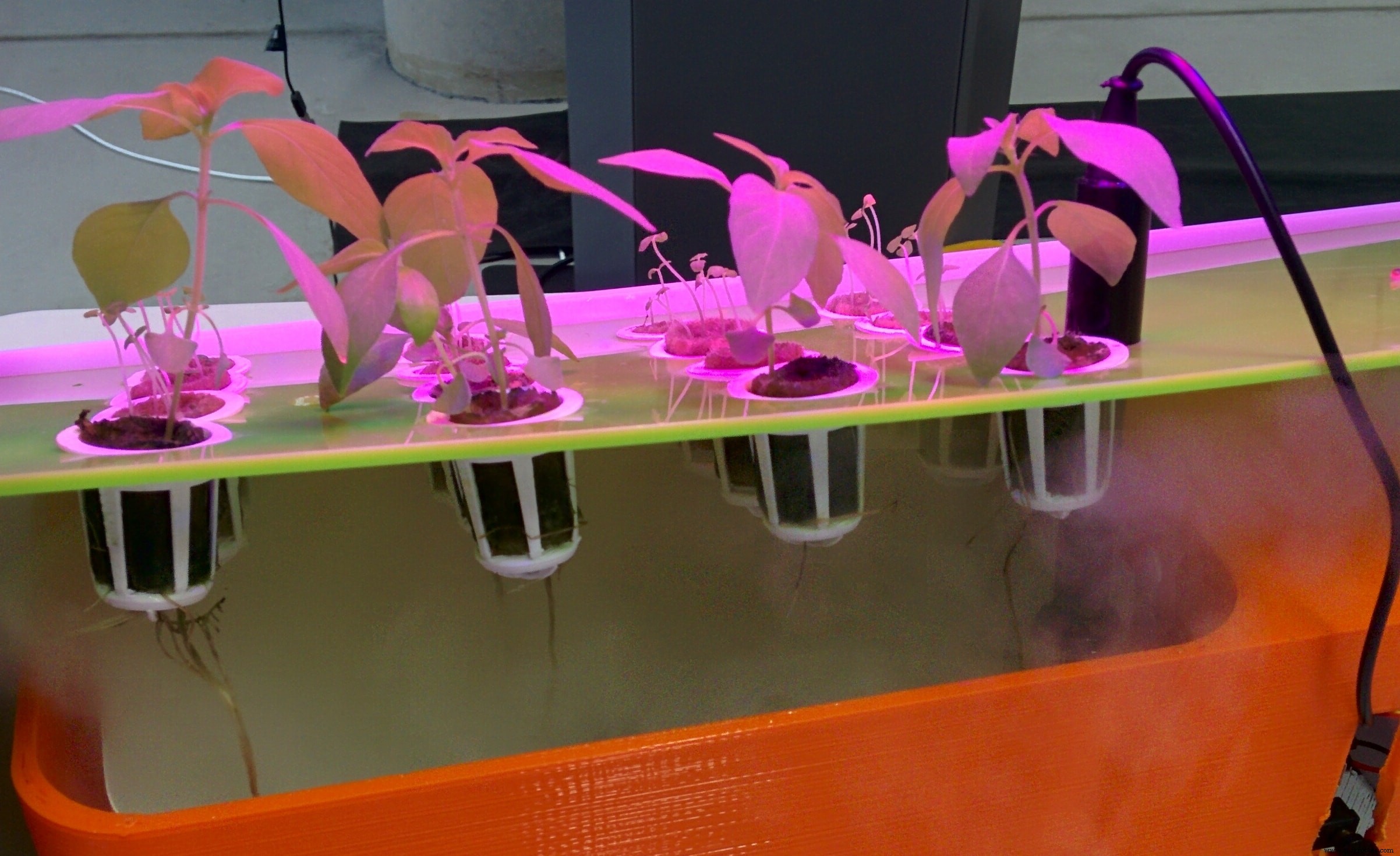
And here it is the system!!! Everything assembled, nice looking growing system GIY
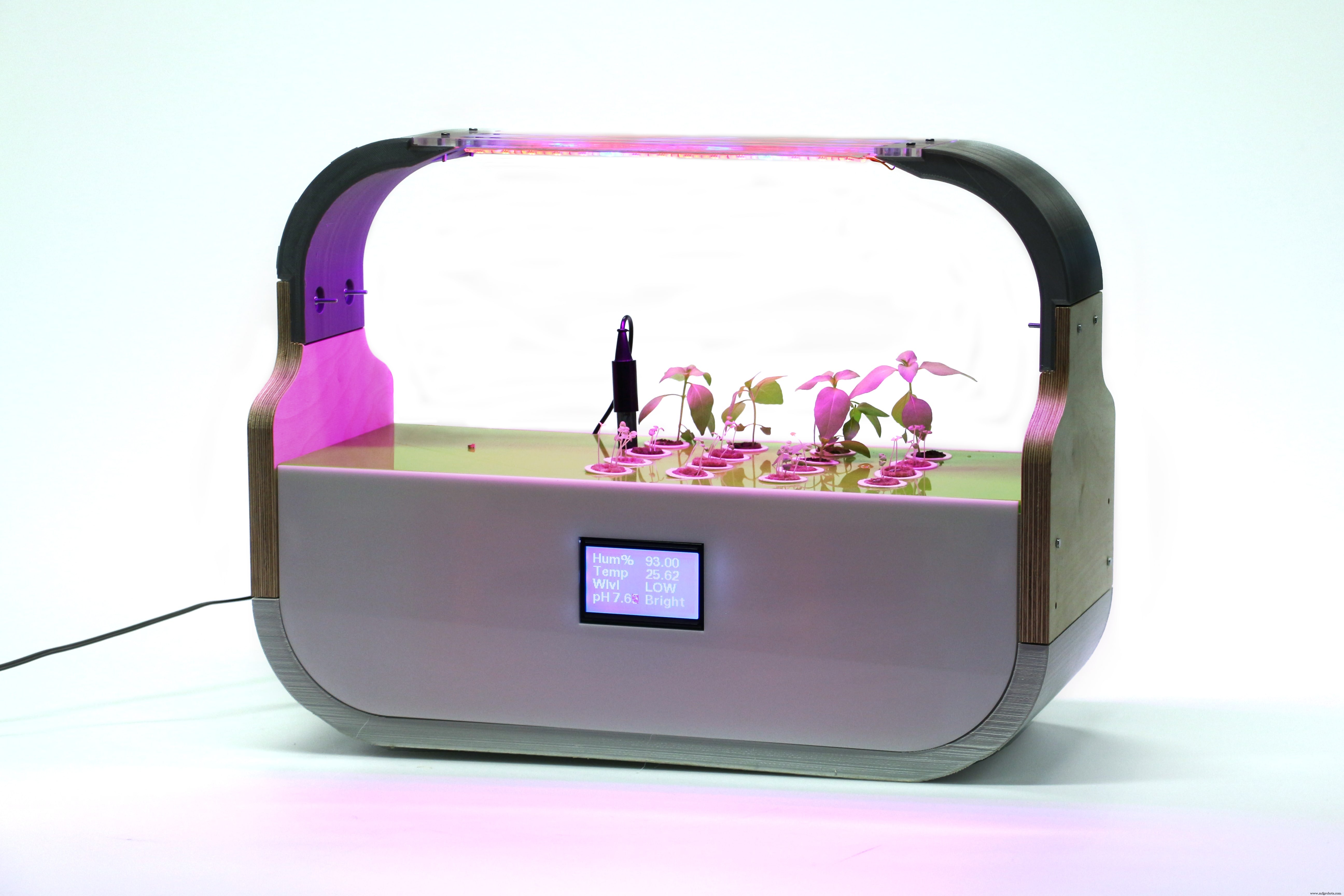
A HERO shot during the working process!
Final Presentation Video
© 2017 Albot Dima. All rights reserved | [email protected]
This work is licensed under a Creative Commons Attribution-NonCommercial-ShareAlike 4.0 International License.

For selengkapnya details about yang project, please visit yang official source:
http://archive.fabacademy.org/2017/fablabkamplintfort/students/396/final.html
Kode
- GIY Board - CODE
- GIY BOARD - LCD + LIGHT CODE
GIY Board - CODEArduino
#include "dht.h"#include "U8glib.h"#include #include #define DHT11_PIN 2 // what digital pin we're connected to#define ONE_WIRE_BUS 3#define WATER_LEVEL A4#define LDR_PIN A3#define PH_PIN A5#define GROW_LIGHT 10#define FOG_PUMP 13int waterLevel;int LightLevel;int pH;dht DHT;OneWire oneWire(ONE_WIRE_BUS); DallasTemperature waterTemp(&oneWire);U8GLIB_ST7920_128X64 u8g(4, 12, 6, U8G_PIN_NONE);const unsigned char logo [] PROGMEM ={0xFF, 0xFF, 0xFF, 0xFE, 0x7F, 0xFF, 0xFF, 0xFF, 0x00, 0x00, 0x00, 0x00, 0x00, 0x00, 0x00, 0x00,0xFF, 0xFF, 0xFF, 0x00, 0x00, 0xFF, 0xFF, 0xFF, 0x00, 0x00, 0x00, 0x00, 0x00, 0x00, 0x00, 0x00,0xFF, 0xFF, 0xF8, 0x00, 0x00, 0x1F, 0xFF, 0xFF, 0x00, 0x00, 0x00, 0x00, 0x00, 0x00, 0x00, 0x00,0xFF, 0xFF, 0xC0, 0x00, 0x00, 0x03, 0xFF, 0xFF, 0x00, 0x00, 0x00, 0x00, 0x00, 0x00, 0x00, 0x00,0xFF, 0xFF, 0x00, 0x00, 0x00, 0x00, 0xFF, 0xFF, 0x00, 0x00, 0x00, 0x00, 0x00, 0x00, 0x00, 0x00,0xFF, 0xFE, 0x00, 0x03, 0xC0, 0x00, 0x7F, 0xFF, 0x00, 0x00, 0x00, 0x00, 0x00, 0x00, 0x00, 0x00,0xFF, 0xF8, 0x00, 0x07, 0xE0, 0x00, 0x3F, 0xFF, 0x00, 0x00, 0x00, 0x00, 0x00, 0x00, 0x00, 0x00,0xFF, 0xF0, 0x00, 0x1F, 0xF8, 0x00, 0x0F, 0xFF, 0x00, 0x00, 0x00, 0x00, 0x00, 0x00, 0x00, 0x00,0xFF, 0xE0, 0x00, 0x3F, 0xFE, 0x00, 0x07, 0xFF, 0x00, 0x00, 0x00, 0x00, 0x00, 0x00, 0x00, 0x00,0xFF, 0xC0, 0x00, 0 x18, 0x1F, 0x00, 0x03, 0xFF, 0x00, 0x00, 0x00, 0x00, 0x00, 0x00, 0x00, 0x00,0xFF, 0x80, 0x00, 0x00, 0x03, 0xC0, 0x01, 0xFF, 0x00, 0x00, 0x00, 0x00, 0x00, 0x00, 0x00, 0x00,0xFF, 0x00, 0x00, 0x00, 0x00, 0xF0, 0x00, 0xFF, 0x00, 0x00, 0x00, 0x00, 0x00, 0x00, 0x00, 0x00,0xFE, 0x00, 0x00, 0x00, 0x00, 0x7C, 0x00, 0x7F, 0x00, 0x00, 0x00, 0x00, 0x00, 0x00, 0x00, 0x00,0xFC, 0x00, 0x00, 0x00, 0x00, 0x3E, 0x00, 0x7F, 0x00, 0x00, 0x00, 0x00, 0x00, 0x00, 0x00, 0x00,0xFC, 0x03, 0x80, 0x00, 0x00, 0x3F, 0x80, 0x3F, 0x00, 0x00, 0x00, 0x00, 0x00, 0x00, 0x00, 0x00,0xF8, 0x07, 0xE0, 0x00, 0x00, 0x1F, 0xE0, 0x1F, 0x00, 0x00, 0x00, 0x00, 0x00, 0x00, 0x00, 0x00,0xFC, 0x1F, 0xF0, 0x00, 0x00, 0x1F, 0xF0, 0x1F, 0x00, 0x00, 0x00, 0x00, 0x00, 0x00, 0x00, 0x00,0xF0, 0x3F, 0xF0, 0x00, 0x00, 0x1F, 0xFC, 0x0F, 0x00, 0x00, 0x00, 0x00, 0x00, 0x00, 0x00, 0x00,0xF0, 0xFF, 0xF0, 0x00, 0x00, 0x1F, 0xFF, 0x0F, 0x00, 0x00, 0x00, 0x00, 0x00, 0x00, 0x00, 0x00,0xE0, 0xFF, 0xF0, 0x00, 0x00, 0x3F, 0xFF, 0x07, 0x00, 0x00, 0x00, 0x0 0, 0x00, 0x00, 0x00, 0x00,0xE0, 0xFF, 0xF0, 0x00, 0x00, 0x3F, 0xFF, 0x07, 0x00, 0x00, 0x00, 0x00, 0x00, 0x00, 0x00, 0x00,0xC0, 0xFF, 0xF8, 0x00, 0x00, 0x7F, 0xFF, 0x03, 0x00, 0x00, 0x00, 0x00, 0x00, 0x00, 0x00, 0x00,0xC0, 0xFF, 0xFC, 0x00, 0x00, 0xFF, 0xFF, 0x03, 0x00, 0x00, 0x00, 0x00, 0x00, 0x00, 0x00, 0x00,0xC0, 0xFF, 0xFF, 0x00, 0x01, 0xFF, 0xFF, 0x03, 0x00, 0x00, 0x00, 0x00, 0x00, 0x00, 0x00, 0x00,0x80, 0xFF, 0xFF, 0xC0, 0x07, 0xFF, 0xFF, 0x01, 0x00, 0x00, 0x00, 0x00, 0x00, 0x00, 0x00, 0x00,0x80, 0xFF, 0xFF, 0xFF, 0xFF, 0xFF, 0xFF, 0x01, 0x00, 0x00, 0x00, 0x00, 0x00, 0x00, 0x00, 0x00,0x80, 0xFF, 0xFF, 0xFF, 0xFF, 0xFF, 0xFF, 0x01, 0x00, 0x00, 0x00, 0x00, 0x00, 0x00, 0x00, 0x00,0x80, 0xFF, 0xFF, 0xFF, 0xFF, 0xFF, 0xFF, 0x01, 0x00, 0x00, 0x00, 0x00, 0x00, 0x00, 0x00, 0x00,0x80, 0xFE, 0x1F, 0xFF, 0xFF, 0xF0, 0x3C, 0x01, 0x00, 0x00, 0x00, 0x00, 0x00, 0x00, 0x00, 0x00,0x80, 0xF8, 0x03, 0xFF, 0xFF, 0xC0, 0x10, 0x01, 0x00, 0x00, 0x00, 0x00, 0x00, 0x00, 0x00, 0x00,0x80, 0xF0, 0x01, 0xFF, 0xFF, 0x80, 0x00, 0x01, 0x00, 0x00, 0x00, 0x00, 0x00, 0x00, 0x00, 0x00,0x00, 0xF0, 0x00, 0xFF, 0xFF, 0x00, 0x00, 0x01, 0x00, 0x00, 0x00, 0x00, 0x00, 0x00, 0x00, 0x00,0x00, 0xE0, 0x00, 0x7F, 0xFE, 0x00, 0x00, 0x01, 0x00, 0x00, 0x00, 0x00, 0x00, 0x00, 0x00, 0x00,0x80, 0xE0, 0x00, 0x3F, 0xFC, 0x00, 0x00, 0x01, 0x00, 0x00, 0x00, 0x00, 0x00, 0x00, 0x00, 0x00,0x80, 0xE0, 0x00, 0x1F, 0xFC, 0x00, 0x00, 0x01, 0x00, 0x00, 0x00, 0x00, 0x00, 0x00, 0x00, 0x00,0x80, 0xE0, 0x00, 0x1F, 0xF8, 0x00, 0x00, 0x01, 0x00, 0x00, 0x00, 0x00, 0x00, 0x00, 0x00, 0x00,0x80, 0xE0, 0x00, 0x0F, 0xF8, 0x00, 0x00, 0x01, 0x00, 0x00, 0x00, 0x00, 0x00, 0x00, 0x00, 0x00,0x80, 0xE0, 0x00, 0x0F, 0xF0, 0x00, 0x00, 0x01, 0x00, 0x00, 0x00, 0x00, 0x00, 0x00, 0x00, 0x00,0x80, 0xE0, 0x00, 0x0F, 0xF0, 0x00, 0x01, 0x01, 0x00, 0x00, 0x00, 0x00, 0x00, 0x00, 0x00, 0x00,0x80, 0xE0, 0x00, 0x07, 0xF0, 0x00, 0x07, 0x01, 0x00, 0x00, 0x00, 0x00, 0x00, 0x00, 0x00, 0x00,0xC0, 0xF0, 0x00, 0x07, 0xF0, 0x00, 0x07, 0x03, 0x00, 0x00, 0x00, 0x00, 0x 00, 0x00, 0x00, 0x00,0xC0, 0xF0, 0x00, 0x07, 0xF0, 0x00, 0x0F, 0x03, 0x00, 0x00, 0x00, 0x00, 0x00, 0x00, 0x00, 0x00,0xC0, 0xF8, 0x00, 0x07, 0xF0, 0x00, 0x0F, 0x03, 0x00, 0x00, 0x00, 0x00, 0x00, 0x00, 0x00, 0x00,0xC0, 0xF8, 0x00, 0x07, 0xF0, 0x00, 0x1F, 0x07, 0x00, 0x00, 0x00, 0x00, 0x00, 0x00, 0x00, 0x00,0xE0, 0xFC, 0x00, 0x07, 0xF0, 0x00, 0x1F, 0x07, 0x00, 0x00, 0x00, 0x00, 0x00, 0x00, 0x00, 0x00,0xE0, 0xFE, 0x00, 0x0F, 0xF0, 0x00, 0x3F, 0x07, 0x00, 0x00, 0x00, 0x00, 0x00, 0x00, 0x00, 0x00,0xF0, 0x3E, 0x00, 0x0F, 0xF0, 0x00, 0x7C, 0x0F, 0x00, 0x00, 0x00, 0x00, 0x00, 0x00, 0x00, 0x00,0xF0, 0x1E, 0x00, 0x1F, 0xF8, 0x00, 0xF8, 0x0F, 0x00, 0x00, 0x00, 0x00, 0x00, 0x00, 0x00, 0x00,0xF8, 0x06, 0x00, 0x1F, 0xFC, 0x01, 0xE0, 0x1F, 0x00, 0x00, 0x00, 0x00, 0x00, 0x00, 0x00, 0x00,0xFC, 0x00, 0x00, 0x7F, 0xFF, 0x0F, 0x80, 0x3F, 0x00, 0x00, 0x00, 0x00, 0x00, 0x00, 0x00, 0x00,0xFC, 0x00, 0x00, 0x7F, 0xFF, 0xFF, 0x00, 0x3F, 0x00, 0x00, 0x00, 0x00, 0x00, 0x00, 0x00, 0x00,0xFE, 0x00, 0x00, 0x7F, 0xFF, 0xFC, 0x00, 0x7F, 0x00, 0x00, 0x00, 0x00, 0x00, 0x00, 0x00, 0x00,0xFF, 0x00, 0x00, 0x7F, 0xFF, 0xF0, 0x00, 0xFF, 0x00, 0x00, 0x00, 0x00, 0x00, 0x00, 0x00, 0x00,0xFF, 0x80, 0x00, 0x7F, 0xFF, 0xC0, 0x01, 0xFF, 0x00, 0x00, 0x00, 0x00, 0x00, 0x00, 0x00, 0x00,0xFF, 0xC0, 0x00, 0x7F, 0xFF, 0x80, 0x03, 0xFF, 0x00, 0x00, 0x00, 0x00, 0x00, 0x00, 0x00, 0x00,0xFF, 0xE0, 0x00, 0x7F, 0xFE, 0x00, 0x07, 0xFF, 0x00, 0x00, 0x00, 0x00, 0x00, 0x00, 0x00, 0x00,0xFF, 0xF0, 0x00, 0x1F, 0xF8, 0x00, 0x0F, 0xFF, 0x00, 0x00, 0x00, 0x00, 0x00, 0x00, 0x00, 0x00,0xFF, 0xF8, 0x00, 0x0F, 0xF0, 0x00, 0x1F, 0xFF, 0x00, 0x00, 0x00, 0x00, 0x00, 0x00, 0x00, 0x00,0xFF, 0xFC, 0x00, 0x03, 0xC0, 0x00, 0x3F, 0xFF, 0x00, 0x00, 0x00, 0x00, 0x00, 0x00, 0x00, 0x00,0xFF, 0xFF, 0x00, 0x00, 0x00, 0x00, 0xFF, 0xFF, 0x00, 0x00, 0x00, 0x00, 0x00, 0x00, 0x00, 0x00,0xFF, 0xFF, 0xC0, 0x00, 0x00, 0x03, 0xFF, 0xFF, 0x00, 0x00, 0x00, 0x00, 0x00, 0x00, 0x00, 0x00,0xFF, 0xFF, 0xF0, 0x00, 0x00, 0x1F, 0xFF, 0xFF, 0x00, 0x00, 0x00, 0x00, 0x00, 0 x00, 0x00, 0x00,0xFF, 0xFF, 0xFE, 0x00, 0x00, 0x7F, 0xFF, 0xFF, 0x00, 0x00, 0x00, 0x00, 0x00, 0x00, 0x00, 0x00,0xFF, 0xFF, 0xFF, 0xFD, 0x3F, 0xFF, 0xFF, 0xFF, 0x00, 0x00, 0x00, 0x00, 0x00, 0x00, 0x00, 0x00};bool first;float hum =0.0;double T=0.0;void dht_test(float * humPerc);void setup(void) { waterTemp.begin(); pinMode (GROW_LIGHT, OUTPUT); pinMode (FOG_PUMP, OUTPUT); digitalWrite (GROW_LIGHT, HIGH); first =true; // menetapkan nilai warna default jika ( u8g.getMode() ==U8G_MODE_R3G3B2 ) { u8g.setColorIndex(255); // white } else if ( u8g.getMode() ==U8G_MODE_GRAY2BIT ) { u8g.setColorIndex(3); // max intensity } else if ( u8g.getMode() ==U8G_MODE_BW ) { u8g.setColorIndex(1); // pixel on } else if ( u8g.getMode() ==U8G_MODE_HICOLOR ) { u8g.setHiColorByRGB(255,255,255); } // picture loop u8g.firstPage(); do { u8g.drawBitmapP( 32, 0, 16, 64, logo); } while( u8g.nextPage() ); dht_test(&hum);}void RefreshDisplay(float * humPerc, double *T, int *WL, int *LL, int *pH_value) { u8g.setFont(u8g_font_fub11); u8g.setFontRefHeightExtendedText(); u8g.setDefaultForegroundColor(); u8g.setFontPosTop(); u8g.drawStr( 4, 0, "Hum%"); u8g.setPrintPos( 68, 0); u8g.print( *humPerc); u8g.drawStr( 4, 15, "Temp"); u8g.setPrintPos( 68, 15); u8g.print( *T); u8g.drawStr( 4, 30, "Wlvl"); if (*WL ==0){ u8g.drawStr (68, 30,"EMPTY!"); digitalWrite (FOG_PUMP, LOW); } else{ if (*WL <800) u8g.drawStr (68, 30,"LOW"); else { digitalWrite(FOG_PUMP, HIGH); u8g.drawStr (68, 30,"HIGH"); } } if (*LL <100) { u8g.drawStr (68, 45,"Dark"); } else if (*LL <200) { u8g.drawStr (68, 45,"Dim"); } else if (*LL <500) { u8g.drawStr (68, 45,"Light"); } else if (*LL <800) { u8g.drawStr (68, 45,"Bright"); } else { u8g.drawStr (68, 45,"2Bright"); } double voltage =5.0 / 1024.0 * (*pH_value); float Po =7 + ((2.5 - voltage) / 0.18); u8g.drawStr (4, 45,"pH"); u8g.setPrintPos( 28, 45); u8g.print( Po); }void loop(void) {waterTemp.requestTemperatures();T =waterTemp.getTempCByIndex(0);waterLevel =analogRead(WATER_LEVEL);LightLevel =analogRead(LDR_PIN);pH =analogRead (PH_PIN);char status;int chk =DHT.read11(DHT11_PIN);hum =DHT.humidity; dht_test(&hum); if(first) { first =false; } else { u8g.firstPage(); do { RefreshDisplay(&hum, &T,&waterLevel, &LightLevel, &pH); } while( u8g.nextPage() ); }}void dht_test(float * humPerc) { // Wait a few seconds between measurements. delay(1000);}
GIY BOARD - LCD + LIGHT CODEArduino
#include "U8glib.h"int led =10;U8GLIB_ST7920_128X64 u8g(4, 12, 6, U8G_PIN_NONE);void draw(void) { // graphic commands to redraw the complete screen should be placed here u8g.setFont(u8g_font_unifont); u8g.setPrintPos(0, 20); // call procedure from base class, http://arduino.cc/en/Serial/Print u8g.print("GIY Project v1.0!");}void setup(void) { pinMode (led, OUTPUT); digitalWrite (led, HIGH);}void loop(void) { // picture loop u8g.firstPage(); melakukan { menggambar(); } while( u8g.nextPage() ); // rebuild the picture after some delay delay(500);} Skema