Logika Kombinasi dengan selalu
Verilog selalu memblokir dapat digunakan untuk logika sekuensial dan kombinasional. Beberapa contoh desain ditampilkan menggunakan assign pernyataan di artikel sebelumnya. Kumpulan desain yang sama akan dieksplorasi selanjutnya menggunakan always blokir.
Contoh #1 :Logika kombinasional sederhana
Kode yang ditunjukkan di bawah ini mengimplementasikan logika kombinasional digital sederhana yang memiliki sinyal keluaran yang disebut z dengan tipe reg yang diperbarui setiap kali salah satu sinyal dalam daftar sensitivitas mengubah nilainya. Daftar sensitivitas dideklarasikan dalam tanda kurung setelah @ operator.
module combo ( 	input 	a, b, c, d, e,
								output 	reg z);

	always @ ( a or b or c or d or e) begin
		z = ((a & b) | (c ^ d) & ~e);
	end

endmodule
Modul kombo akan diuraikan ke dalam skema perangkat keras berikut menggunakan alat sintesis dan dapat dilihat bahwa logika kombinasional diimplementasikan dengan gerbang digital.
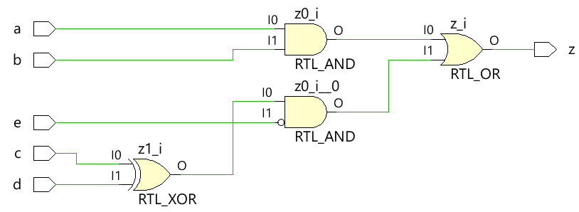
 Gunakan penetapan pemblokiran saat memodelkan logika kombinasional dengan blok selalu
Testbench
Testbench adalah platform untuk mensimulasikan desain untuk memastikan bahwa desain berperilaku seperti yang diharapkan. Semua kombinasi input didorong ke modul desain menggunakan for loop dengan pernyataan penundaan 10 unit waktu sehingga nilai baru diterapkan ke input setelah beberapa waktu.
module tb;
	// Declare testbench variables
  reg a, b, c, d, e;
  wire z;
  integer i;

  // Instantiate the design and connect design inputs/outputs with
  // testbench variables
  combo u0 ( .a(a), .b(b), .c(c), .d(d), .e(e), .z(z));

  initial begin
  	// At the beginning of time, initialize all inputs of the design
  	// to a known value, in this case we have chosen it to be 0.
    a <= 0;
    b <= 0;
    c <= 0;
    d <= 0;
    e <= 0;

    // Use a $monitor task to print any change in the signal to
    // simulation console
    $monitor ("a=%0b b=%0b c=%0b d=%0b e=%0b z=%0b",
              a, b, c, d, e, z);

    // Because there are 5 inputs, there can be 32 different input combinations
    // So use an iterator "i" to increment from 0 to 32 and assign the value
    // to testbench variables so that it drives the design inputs
    for (i = 0; i < 32; i = i + 1) begin
      {a, b, c, d, e} = i;
      #10;
    end
  end
endmodule
Log Simulasi
ncsim> run
a=0 b=0 c=0 d=0 e=0 z=0
a=0 b=0 c=0 d=0 e=1 z=0
a=0 b=0 c=0 d=1 e=0 z=1
a=0 b=0 c=0 d=1 e=1 z=0
a=0 b=0 c=1 d=0 e=0 z=1
a=0 b=0 c=1 d=0 e=1 z=0
a=0 b=0 c=1 d=1 e=0 z=0
a=0 b=0 c=1 d=1 e=1 z=0
a=0 b=1 c=0 d=0 e=0 z=0
a=0 b=1 c=0 d=0 e=1 z=0
a=0 b=1 c=0 d=1 e=0 z=1
a=0 b=1 c=0 d=1 e=1 z=0
a=0 b=1 c=1 d=0 e=0 z=1
a=0 b=1 c=1 d=0 e=1 z=0
a=0 b=1 c=1 d=1 e=0 z=0
a=0 b=1 c=1 d=1 e=1 z=0
a=1 b=0 c=0 d=0 e=0 z=0
a=1 b=0 c=0 d=0 e=1 z=0
a=1 b=0 c=0 d=1 e=0 z=1
a=1 b=0 c=0 d=1 e=1 z=0
a=1 b=0 c=1 d=0 e=0 z=1
a=1 b=0 c=1 d=0 e=1 z=0
a=1 b=0 c=1 d=1 e=0 z=0
a=1 b=0 c=1 d=1 e=1 z=0
a=1 b=1 c=0 d=0 e=0 z=1
a=1 b=1 c=0 d=0 e=1 z=1
a=1 b=1 c=0 d=1 e=0 z=1
a=1 b=1 c=0 d=1 e=1 z=1
a=1 b=1 c=1 d=0 e=0 z=1
a=1 b=1 c=1 d=0 e=1 z=1
a=1 b=1 c=1 d=1 e=0 z=1
a=1 b=1 c=1 d=1 e=1 z=1
ncsim: *W,RNQUIE: Simulation is complete.
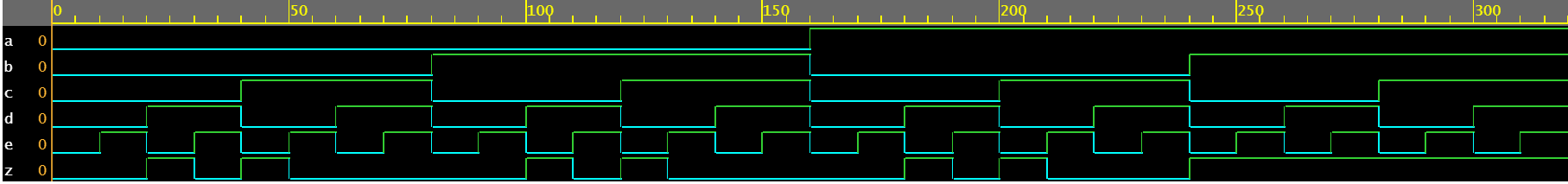
Perhatikan bahwa kedua metode, assign dan always , diimplementasikan ke dalam logika perangkat keras yang sama.
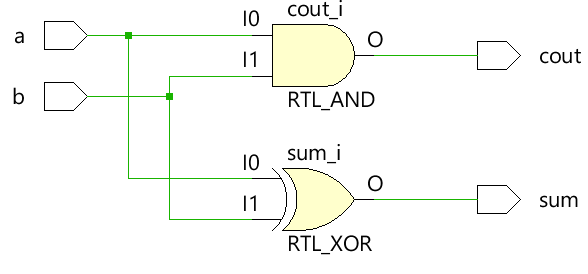
Contoh #2:Half Adder
Modul penambah setengah menerima dua input skalar a dan b dan menggunakan logika kombinasional untuk menetapkan jumlah sinyal keluaran dan membawa bit cout. Penjumlahan didorong oleh XOR antara a dan b sedangkan bit pembawa diperoleh oleh AND antara dua input.
module ha ( input 	a, b,
						output	sum, cout);

	always @ (a or b) begin
		{cout, sum} = a + b;
	end

endmodule
Testbench
module tb;
	// Declare testbench variables
  reg a, b;
  wire sum, cout;
  integer i;

  // Instantiate the design and connect design inputs/outputs with
  // testbench variables
  ha u0 ( .a(a), .b(b), .sum(sum), .cout(cout));

  initial begin
  	// At the beginning of time, initialize all inputs of the design
  	// to a known value, in this case we have chosen it to be 0.
    a <= 0;
    b <= 0;

    // Use a $monitor task to print any change in the signal to
    // simulation console
    $monitor("a=%0b b=%0b sum=%0b cout=%0b", a, b, sum, cout);

    // Because there are only 2 inputs, there can be 4 different input combinations
    // So use an iterator "i" to increment from 0 to 4 and assign the value
    // to testbench variables so that it drives the design inputs
    for (i = 0; i < 4; i = i + 1) begin
      {a, b} = i;
      #10;
    end
  end
endmodule
Log Simulasi
ncsim> run
a=0 b=0 sum=0 cout=0
a=0 b=1 sum=1 cout=0
a=1 b=0 sum=1 cout=0
a=1 b=1 sum=0 cout=1
ncsim: *W,RNQUIE: Simulation is complete.

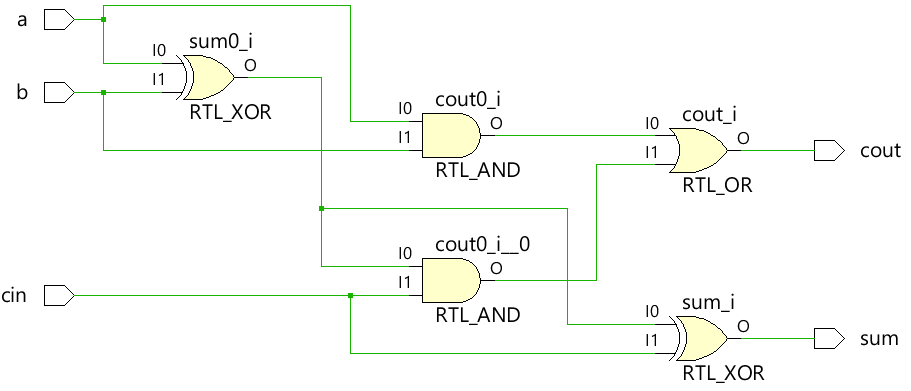
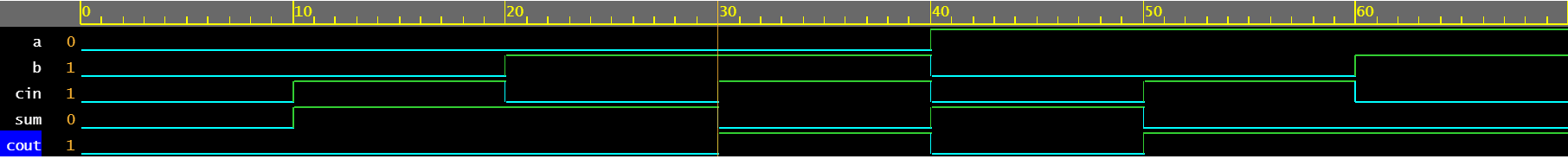
Contoh #3:Penambah Penuh
Blok selalu dapat digunakan untuk menggambarkan perilaku penambah penuh untuk menggerakkan jumlah dan cout keluaran.
module fa (	input 	a, b, cin,
			output reg	sum, cout);

  always @ (a or b or cin) begin
    {cout, sum} = a + b + cin;
  end

endmodule
Testbench
module tb;
  reg a, b, cin;
  wire sum, cout;
  integer i;

  fa u0 ( .a(a), .b(b), .cin(cin), .sum(sum), .cout(cout));

  initial begin
    a <= 0;
    b <= 0;

    $monitor("a=%0b b=%0b cin=%0b cout=%0b sum=%0b", a, b, cin, cout, sum);

    for (i = 0; i < 8; i = i + 1) begin
      {a, b, cin} = i;
      #10;
    end
  end
endmodule
Log Simulasi
ncsim> run
a=0 b=0 cin=0 cout=0 sum=0
a=0 b=0 cin=1 cout=0 sum=1
a=0 b=1 cin=0 cout=0 sum=1
a=0 b=1 cin=1 cout=1 sum=0
a=1 b=0 cin=0 cout=0 sum=1
a=1 b=0 cin=1 cout=1 sum=0
a=1 b=1 cin=0 cout=1 sum=0
a=1 b=1 cin=1 cout=1 sum=1
ncsim: *W,RNQUIE: Simulation is complete.
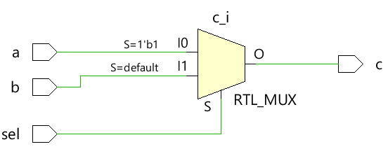
Contoh #4:Multiplexer 2x1
Multiplexer 2x1 sederhana menggunakan operator ternary untuk memutuskan input mana yang harus diberikan ke output c. Jika sel adalah 1, output didorong oleh a dan jika sel adalah 0 output didorong oleh b.
module mux_2x1 (input 	a, b, sel,
				output 	reg c);


  always @ ( a or b or sel) begin
	c = sel ? a : b;
  end
endmodule
Testbench
module tb;
	// Declare testbench variables
  reg a, b, sel;
  wire c;
  integer i;

  // Instantiate the design and connect design inputs/outputs with
  // testbench variables
  mux_2x1 u0 ( .a(a), .b(b), .sel(sel), .c(c));

  initial begin
  	// At the beginning of time, initialize all inputs of the design
  	// to a known value, in this case we have chosen it to be 0.
    a <= 0;
    b <= 0;
    sel <= 0;

    $monitor("a=%0b b=%0b sel=%0b c=%0b", a, b, sel, c);

    for (i = 0; i < 3; i = i + 1) begin
      {a, b, sel} = i;
      #10;
    end
  end
endmodule
Log Simulasi
ncsim> run
a=0 b=0 sel=0 c=0
a=0 b=0 sel=1 c=0
a=0 b=1 sel=0 c=1
ncsim: *W,RNQUIE: Simulation is complete.

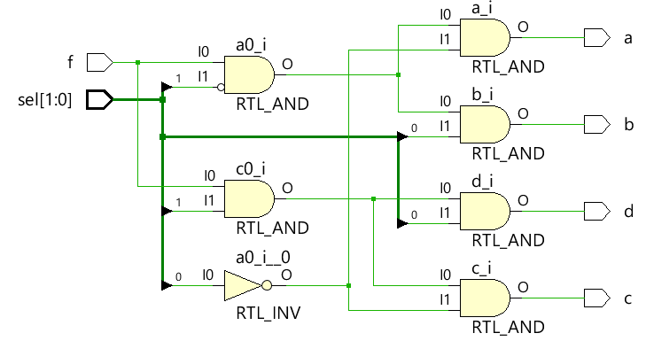
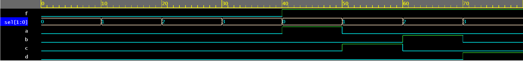
Contoh #5:Demultiplexer 1x4
Demultiplexer menggunakan kombinasi input sel dan f untuk menggerakkan sinyal output yang berbeda. Setiap sinyal keluaran bertipe reg dan digunakan di dalam always blok yang diperbarui berdasarkan perubahan sinyal yang tercantum dalam daftar sensitivitas.
module demux_1x4 (	input 				f,
										input [1:0]	 	sel,
										output reg		a, b, c, d);

  always @ ( f or sel) begin
    a = f & ~sel[1] & ~sel[0];
    b = f &  sel[1] & ~sel[0];
    c = f & ~sel[1] &  sel[0];
    d = f &  sel[1] &  sel[0];
  end

endmodule
Testbench
module tb;
	// Declare testbench variables
  reg f;
  reg [1:0] sel;
  wire a, b, c, d;
  integer i;

  // Instantiate the design and connect design inputs/outputs with
  // testbench variables
  demux_1x4 u0 ( .f(f), .sel(sel), .a(a), .b(b), .c(c), .d(d));

  // At the beginning of time, initialize all inputs of the design
  // to a known value, in this case we have chosen it to be 0.
  initial begin
    f <= 0;
    sel <= 0;

    $monitor("f=%0b sel=%0b a=%0b b=%0b c=%0b d=%0b", f, sel, a, b, c, d);

    // Because there are 3 inputs, there can be 8 different input combinations
    // So use an iterator "i" to increment from 0 to 8 and assign the value
    // to testbench variables so that it drives the design inputs
    for (i = 0; i < 8; i = i + 1) begin
      {f, sel} = i;
      #10;
    end
  end
endmodule
Log Simulasi
ncsim> run
f=0 sel=0 a=0 b=0 c=0 d=0
f=0 sel=1 a=0 b=0 c=0 d=0
f=0 sel=10 a=0 b=0 c=0 d=0
f=0 sel=11 a=0 b=0 c=0 d=0
f=1 sel=0 a=1 b=0 c=0 d=0
f=1 sel=1 a=0 b=0 c=1 d=0
f=1 sel=10 a=0 b=1 c=0 d=0
f=1 sel=11 a=0 b=0 c=0 d=1
ncsim: *W,RNQUIE: Simulation is complete.
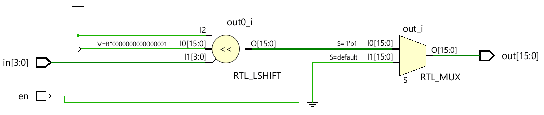
Contoh #6:Dekoder 4x16
module dec_3x8 ( 	input 			en,
					input 	[3:0] 	in,
					output  reg [15:0] 	out);

  always @ (en or in) begin
    out = en ? 1 << in: 0;
  end

endmodule
Testbench
module tb;
  reg en;
  reg [3:0] in;
  wire [15:0] out;
  integer i;

  dec_3x8 u0 ( .en(en), .in(in), .out(out));

  initial begin
    en <= 0;
    in <= 0;

    $monitor("en=%0b in=0x%0h out=0x%0h", en, in, out);

    for (i = 0; i < 32; i = i + 1) begin
      {en, in} = i;
      #10;
    end
  end
endmodule
Log Simulasi
ncsim> run
en=0 in=0x0 out=0x0
en=0 in=0x1 out=0x0
en=0 in=0x2 out=0x0
en=0 in=0x3 out=0x0
en=0 in=0x4 out=0x0
en=0 in=0x5 out=0x0
en=0 in=0x6 out=0x0
en=0 in=0x7 out=0x0
en=0 in=0x8 out=0x0
en=0 in=0x9 out=0x0
en=0 in=0xa out=0x0
en=0 in=0xb out=0x0
en=0 in=0xc out=0x0
en=0 in=0xd out=0x0
en=0 in=0xe out=0x0
en=0 in=0xf out=0x0
en=1 in=0x0 out=0x1
en=1 in=0x1 out=0x2
en=1 in=0x2 out=0x4
en=1 in=0x3 out=0x8
en=1 in=0x4 out=0x10
en=1 in=0x5 out=0x20
en=1 in=0x6 out=0x40
en=1 in=0x7 out=0x80
en=1 in=0x8 out=0x100
en=1 in=0x9 out=0x200
en=1 in=0xa out=0x400
en=1 in=0xb out=0x800
en=1 in=0xc out=0x1000
en=1 in=0xd out=0x2000
en=1 in=0xe out=0x4000
en=1 in=0xf out=0x8000
ncsim: *W,RNQUIE: Simulation is complete.


