Sistem Deteksi Kebocoran Air Pintar dan Kontrol Klep
Komponen dan Perlengkapan
Kotak pelindung aluminium
×
1
Arduino UNO
×
1
Arduino Ethernet Shield 2
×
1
Sumber daya listrik
×
1
Perunderian AC
×
1
Kit LED dengan resistor
×
1
Relais (1 dual 5V dan 1 dual 12V)
×
1
Klep motoris
×
1
Konektor JST
×
1
Sensor air
×
1
Tentang Proyek Ini
Ringkasan
Selama obrolan dengan seorang teman, saya menyadari bahwa kebocoran air merupakan masalah serius. Teman saya pernah harus mengganti semua furnitur di bawah tanahnya hanya karena sebuah pipa pecah saat dia sedang bekerja.
Proyek ini serupa dengan yang saya publikasikan untuk kontes Microsoft IoT, tetapi versi ini didasarkan pada Arduino, bukan Raspberry. Pandangan saya adalah sebagai berikut: alih-alih memusatkan banyak tanggung jawab pada platform besar (seperti RasPi, DragonBoard, atau PC), saya lebih memilih untuk mendelegasikan tanggung jawab sederhana kepada perangkat sederhana (seperti Arduino dan lainnya). Mereka akan melakukan apa yang seharusnya dilakukan, dan sebagai opsi, mereka akan terhubung melalui jaringan ke perangkat lain (sederhana atau kompleks) untuk menawarkan layanan canggih. Dalam hal kegagalan jaringan, mereka tetap melanjutkan tugasnya.
Dasarnya, sistem ini memantau kebocoran air dan memicu tindakan seperti menutup masuk air utama, tergantung pada kerusakan yang terdeteksi.
Sistem juga menerbitkan pesan ke MQTT Broker. Ideanya adalah perangkat harus mengelola air secara lokal, tetapi juga terlibat, bersama dengan perangkat lain, dalam sistem yang lebih besar yang mengelola Otomasi Rumah.
Tampilan Sistem
Masuk air utama terletak di bagian bawah. Perangkat pertama dipasang oleh layanan persediaan air kota untuk mengontrol tekanan air. Saya memasang bagian di atas gambar. Klep motoris (berwarna biru) dipasang secara paralel dengan klep manual. Dalam gambar ini, klep manual terbuka dan klep motoris dihindari. Ini berguna dalam hal padam listrik. Dalam mode normal, klep manual harus dimatikan.
Ada motor DC (12V) dalam klep yang berputar searah jarum jam atau berlawanan arah jarum jam tergantung pada polaritas. Ada loop umpan balik yang menunjukkan apakah klep efektif menyala atau mati. Untuk menyalanya, cukup terapkan tegangan positif pada sambungan kiri atas.
Pengontrol
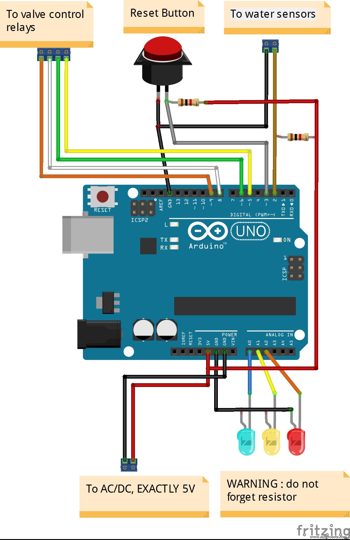
Dari kiri ke kanan: steker AC, tombol reset, beberapa LED untuk menampilkan status, konektor (untuk sensor, untuk motor), antarmuka Ethernet dan USB.
LED1: Merah menyala = air terdeteksi secara lokal, Merah berkedip = air terdeteksi dari jarak jauh, Mati = tidak ada kebocoran air
LED 2: Kuning menyala = tidak dapat mengontrol klep motoris, Kuning berkedip = tidak dapat mencapai MQTT broker, Mati = semua baik-baik saja
LED3: Biru menyala = semua baik-baik saja, Biru berkedip = klep motoris tertutup, Mati = sistem mati atau tidak mendapat daya
Berikut adalah sensor, yang ditempatkan di tempat yang menurut saya air mungkin bocor:
Berikut adalah yang ada di dalamnya:
PERINGATAN!
Sumber daya AC/DC yang saya gunakan memiliki dua keluaran: yang pertama adalah 12V DC dan digunakan untuk mengaktifkan klep motoris (dikontrol oleh dua relais yang mengontrol rotasi motor) dan yang kedua adalah TEPAK 5V DC, untuk mengaktifkan Arduino. Itulah sebabnya saya memberi daya langsung pada rangkaian 5V, bukan pada Vin yang membutuhkan setidaknya 6V DC. Setelah AC/DC terhubung, Anda TIDAK PERNAH (saya berTEPAK TIDAK PERNAH) mencolokkan jack DC Arduino atau kabel USB Arduino. Jika Anda masih ingin men-debug melalui USB, siapkan kabel buatan sendiri TANPA garis daya, simpan hanya garis data. Sebagai tambahan, hubungan antara perunderian AC dan sumber daya AC/DC adalah 110V. Jangan menyentuh, kapan pun!
Kode
Deteksi kebocoran air dan kontrol klep motoris
Pustaka MQTT
Deteksi kebocoran air dan kontrol klep motorisArduino
#include <PubSubClient.h> #include <Network.h> #include <Timer.h> #include <SPI.h> #include <Ethernet.h> #include <Dns.h> #include <avr/wdt.h> /* Here is how the HW works Therea are three subsystems: - the main box : - an Arduino Uno with and Ethernet shield - a red LED : steady when water is detected localy blinking when water is detected remotely , off otherwise - a yellow LED : steady when valve is out of order, blinking when MQTT broker is unreachable (for any reason), off otherwise - a blue LED : steady when valve is open and system is monitoring leakages, blinking when valve has been turned off off is system is down - a push button : once pressed, a self-test is triggered - a dual relay to control a remote motorized valve - another dual relay to sense the open/close limit switches installed on the remote valve - a set of water detectors (all in parrallel) (all 3 connectors on the fron panel are connected in parralel) The motorized valve has the following connections: - Yellow and Blue : DC to power the motor - Black : limit switches input (will be set to GND in our circuit) - Red = will turn to GND when the valve hits its fully closed position (note: due to the internal design of the limit switch, there is no guarantee that continuity will remain once the valve if powerd off) - Green = will turn to GND when the valve hits its fully open position (note: due to the internal design of the limit switch, there is no guarantee that continuity will remain once the valve if powerd off) */ // Network byte mac[] = { 0xDE, 0xAD, 0xBE, 0xCF, 0xFC, 0xEE }; // Arduino's MAC address IPAddress ip(192, 168, 12, 215); // Arduino's IP address IPAddress server(192, 168, 12, 130); // MQTT broker's address EthernetClient ethClient; // MQTT PubSubClient client(ethClient); #define mqttClientPrefix "GLX" // Prefix to use any MQTT publication/subscription #define mqttClientLocation "BASEMENT" // Second part of the client identifier #define mqttClientUID "001" // Last part of the client identifier #define mqttClientStatusTopic "Status" // Topic to be used to publish device status #define mqttClientFaultTopic "Fault" // Topic to be used to publish/subscribe to Faults const int mqttInterval = 20; // determines how often the system will report to MQTT broker (ie. every mqttInterval * mainLoopDelay ms ) int mqttIntervalCnt = 0; // local variable used to count down int isConnectedToBroker = -1; // 1 when connected, -1 = unknown, 0 = unable to connected // Pin-out const int SystemLedPin = A0; // Blue led const int FaultLedPin = A1; // Yellow led const int AlarmLedPin = A2; // Red led const int WaterDetectorPin = 2; // goes to LOW when water is detected, otherwise pulled-up to VCC const int ToggleButtonPin = 3; // goes to LOW when someone press on the button and then goes to HIGH when button is released, otherwise pull-down to GND const int SdCardPin = 4; // SD card on ethernet shield, not used const int ValveClosedPin = 5; // goes to LOW when the motor hits the closed switch limit, otherwise pull-up to HIGH const int ValveOpenedPin = 6; // goes to LOW when the motor hits the open switch limit, otherwise pull-up to HIGH const int ValveControl1 = 8; // to control the first relay that controls the motorized valve power supply const int ValveControl2 = 7; // to control the second relay that controls the motorized valve power supply // Note do not use D10, D11, D12 and D13 since those pins are reserved for Ethernet shield // WaterLeakage (local) int isWaterDetected = 0; // status as per the last good reading // WaterLeakage (remote) int isWaterDetectedRemotely = 0; // status as per messages received from other monitoring devices // Motorized valve int isValveClosed = -1; // status of motorized valve (-1 = unknown, 0 = opened, 1 = closed)) const int valveTimeOut = 15; // in sec, max time allowed to open or close valve int isConnectedToValve = -1; // 0 when system cannot control motorized valve, 1 = connected, -1 = unknown // Manual RESET button volatile boolean isResetRequested = 0; // this one will change when button triggers an interrupt // Logic const int mainLoopDelay = 500; // a fixed delay within main loop, in ms void(* resetFunc) (void) = 0; // Initialization void setup() { wdt_disable(); //always good to disable it, if it was left 'on' or you need init time Serial.begin(9600); Serial.println(F("Begin of setup")); // HW setup pinMode (SystemLedPin, OUTPUT); pinMode (FaultLedPin, OUTPUT); pinMode (AlarmLedPin, OUTPUT); pinMode (WaterDetectorPin, INPUT); pinMode (ToggleButtonPin, INPUT); pinMode (ValveOpenedPin, INPUT); // 12V DC relay is idle by default. Pin is connected to NO side of the relay 1 but there is a pull-up. Pin is therefore HIGH by default. pinMode (ValveClosedPin, INPUT); // 12V DC relay is idle by default. Pin is connected to NO side of the relay 2 but there is a pull-up. Pin is therefore HIGH by default. pinMode (ValveControl1, OUTPUT); digitalWrite(ValveControl1, HIGH); // 5V DC relay 1 is idle by default, i.e motor is connected to GND pinMode (ValveControl2, OUTPUT); digitalWrite(ValveControl2, HIGH); // 5V DC relay 2 idle by default, i.e motor is connected to GND pinMode(SdCardPin, OUTPUT); digitalWrite(SdCardPin, HIGH); // to disable SD card since we do not use it // Self test testLeds(); // Network and MQTT setup client.setServer(server, 1883); client.setCallback(MQTTBrokerCallback); Ethernet.begin(mac, ip); Serial.print(F("Current IP is : ")); Serial.print(Ethernet.localIP()); Serial.print(F(" - MQTT broker IP is : ")); Serial.println(server); // Initialy, we don't know valve's status and limit switches are not so reliable. // Let's open motorized valve and wait for completion. Worst case, if it is already opened, it will just hit the limit switch briefly if (openValve() == 0) { Serial.println(F("Valve is open and system is now monitoring")); // There are other monitoring devices in the house, let's listen to the faults they could report to the MQTT broker subscribeToRemoteWaterSensors(); } else { Serial.println(F("Unable to open valve, system is out of order. Please use plumbing bypass")); }; enableInterruptOnResetButton(); delay(1500); // allow hardware to sort itself out Serial.println(F("End of setup")); } // Main loop void loop() { // LEDs configureLedsWithInitialStates(); // React to reset request if (isResetRequested == 1) { Serial.println(F("Someone pushed on the button to reset this device")); publishStatus(); wdt_enable(WDTO_1S); //enable watchdog, will fire in 1 second delay(5000); Serial.println(F("this message should never appear")); } // Let's check now whether any water leakage has been detected readLocalWaterSensor(); if (isWaterDetected == 1 || isWaterDetectedRemotely == 1) { if (isValveClosed == 0){ closeValve();}; } // Publish to MQTT broker if (mqttIntervalCnt == 0) { if (isWaterDetected == 1){ publishFault();} publishStatus(); mqttIntervalCnt = mqttInterval; } else { if (isConnectedToValve == 0) { Serial.println(F("System is out of order - unable to control motorized valve. No monitoring in place")); } else { Serial.print(F(".")); } mqttIntervalCnt = mqttIntervalCnt - 1; } // Take some rest delay(mainLoopDelay / 2 ); client.loop(); // LEDs configureLedsWithFinalStates(); delay(mainLoopDelay / 2); } // // Local water sensor management // void readLocalWaterSensor() { isWaterDetected = !getDebouncedValue(WaterDetectorPin, 100, 10); Serial.print(isWaterDetected); } // // Reset button management // void enableInterruptOnResetButton() { isResetRequested = 0; attachInterrupt(1, onResetRequested, CHANGE); } void onResetRequested() { detachInterrupt(1); isResetRequested = 1; } // Manage valve opening sequence int openValve() { Serial.print(F("Opening valve...")); // first, confirm the valve was closed by forcing the motor to hit briefly the "closed" limit switch again (since those limit switches are not so reliable...) setupRelays(1); if (waitForEndOfCycle(ValveClosedPin) == 0) { // now, let's try to open the valve setupRelays(2); if (waitForEndOfCycle(ValveOpenedPin) == 0) { isConnectedToValve = 1; isValveClosed = 0; setupRelays(0); // power relays OFF Serial.println(F("")); return 0; } } setupRelays(0); // power relays OFF isConnectedToValve = 0; return -1; } // Manage the valve closing sequence int closeValve() { Serial.print(F("Closing valve...")); // first, confirm the valve was open by forcing the motor to hit briefly the "open" limit switch again (since those limit switches are not so reliable...) setupRelays(2); if ( waitForEndOfCycle(ValveOpenedPin) == 0) { // now, let's try to close the valve setupRelays(1); if (waitForEndOfCycle(ValveClosedPin) == 0) { isConnectedToValve = 1; isValveClosed = 1; setupRelays(0); // power relays OFF Serial.println(F("Valve has been turned off. Please inspect carefully all rooms and cleanup detectors")); return 0; } } setupRelays(0); // power relays OFF isConnectedToValve = 0; return -1; } // Setup the relays in order to feed the motor with the right polarity void setupRelays(int scenario) { switch (scenario) { case 0: // all OFF, no power sent the motorized valve digitalWrite(ValveControl1, HIGH); digitalWrite(ValveControl2, HIGH); break; case 1: // closing cycle digitalWrite(ValveControl1, HIGH); digitalWrite(ValveControl2, LOW); break; case 2: // opening cycle digitalWrite(ValveControl1, LOW); digitalWrite(ValveControl2, HIGH); break; default: Serial.print(F("Unexpected relay scenario: ")); Serial.println(scenario); digitalWrite(ValveControl1, HIGH); digitalWrite(ValveControl2, HIGH); break; } } // Wait until the limit switch is hit by motorized valve's motor int waitForEndOfCycle(int limitSwitchPin) { int cnt = valveTimeOut; while (cnt > 0) { if (getDebouncedValue(limitSwitchPin, 10, 10) == LOW) { return 0; } cnt = cnt - 1; Serial.print(F(".")); delay(1000); }; Serial.println(F(" - timeout reached while closing valve. Check whether valve is well powered up and cables are connected.")); return -1; } // This routine helps to avoid false alarms int getDebouncedValue(int inputPin, int intervalInMs, int requiredConfirmations) { int confirmations = 1; int currentValue = digitalRead(inputPin); while (confirmations <= requiredConfirmations) { delay(intervalInMs); if (currentValue == digitalRead(inputPin)) { confirmations = confirmations + 1; } else { confirmations = 1; currentValue = digitalRead(inputPin); } } return currentValue; } // // LEDs management // void configureLedsWithInitialStates() { clearLeds(); // Re-evaluate if (isWaterDetectedRemotely == 1 || isWaterDetected == 1) { digitalWrite(AlarmLedPin, HIGH);}; if (isConnectedToValve == 0 || isConnectedToBroker == 0) { digitalWrite(FaultLedPin, HIGH);}; digitalWrite(SystemLedPin, HIGH); } void configureLedsWithFinalStates() { if (isWaterDetectedRemotely == 1) { digitalWrite(AlarmLedPin, LOW);}; if (isConnectedToBroker == 0) { digitalWrite(FaultLedPin, LOW);}; if (isValveClosed == 1) { digitalWrite(SystemLedPin, LOW);}; } void clearLeds() { digitalWrite(AlarmLedPin, LOW); digitalWrite(FaultLedPin, LOW); digitalWrite(SystemLedPin, LOW); } void testLeds() { clearLeds(); digitalWrite(AlarmLedPin, HIGH); delay(500); digitalWrite(FaultLedPin, HIGH); delay(500); digitalWrite(SystemLedPin, HIGH); delay(500); clearLeds(); } // // MQTT related functions // // Handle incoming MQTT messages void MQTTBrokerCallback(char* subscribedTopic, byte* payload, unsigned int length) { Serial.print(F("New message received from MQTT broker. Topic=")); Serial.print(subscribedTopic); String payloadAsString = (char*)payload; String realPayload = payloadAsString.substring(0,length); // otherwise we get garbage since the buffer is shared between In and Out Serial.print(F(", content=")); Serial.print(realPayload); if (realPayload.indexOf("WaterDetected") > 0 && realPayload.indexOf(mqttClientLocation) == -1 ) // the second part of the test is required to avoid self-triggered faults { isWaterDetectedRemotely = 1; } // for (int i=0;i<length;i++) { // Serial.print((char)payload[i]); // } Serial.println(); } // Build the client identifier String buildClientIdentifier() { String data = mqttClientPrefix; data+="_"; data+= mqttClientLocation; data+="_"; data+= mqttClientUID; return data; } // Build the topic name to be used to publish status String buildDeviceStatusTopic() { String data = mqttClientPrefix; data+="/"; data+=mqttClientLocation; data+="/"; data+=mqttClientUID; data+="/"; data+=mqttClientStatusTopic; return data; } // Build the topic name to be used to publish/subscribe to Faults String buildFaultTopic() { String data = mqttClientPrefix; data+="/"; data+=mqttClientLocation; data+="/"; data+=mqttClientUID; data+="/"; data+=mqttClientFaultTopic; return data; } // Build the topic name to be used to publish/subscribe to Faults String buildAnyFaultTopic() { String data = mqttClientPrefix; data+="/"; data+="+"; data+="/"; data+="+"; data+="/"; data+=mqttClientFaultTopic; return data; } // Build a JSON message to send to MQTT Broker // NOTE : MQTT_MAX_PACKET_SIZE = 128 bytes.. therefore not more than 100 for the payload // unless you change it in /Arduino/libraries/pubSubClient/src/PubSubClient.h String buildDeviceStatusJson() { String data = "{"; data+="\n"; data+="\"ResetByOperator\": "; data+=(int)isResetRequested; data+= ","; data+="\n"; data+="\"WaterDetected\": "; data+=(int)isWaterDetected; data+= ","; data+="\n"; data+="\"ValveClosed\": "; data+=(int)isValveClosed; data+= ","; data+="\n"; data+="\"ValveDetected\": "; data+=(int)isConnectedToValve; data+="\n"; data+="}"; return data; } // Build a JSON message to send to MQTT Broker // NOTE : MQTT_MAX_PACKET_SIZE = 128 bytes.. therefore not more than 100 for the payload // unless you change it in /Arduino/libraries/pubSubClient/src/PubSubClient.h String buildFaultJson() { String data = "{"; data+="\n"; data+="\"WaterDetected\": "; data+=(int)isWaterDetected; data+= ","; data+="\n"; data+="\"Location\": "; data+=mqttClientLocation; data+="\n"; data+="}"; return data; } // Report to MQTT broker void publishMsg(char (&topic)[200], char (&payload)[200] ) { if (connectToBroker() == true) { if (client.publish(topic, payload) == true) { isConnectedToBroker = 1; Serial.print(F("Message sent to MQTT broker using the following topic ")); Serial.println(topic); } else { Serial.print(F("Message NOT sent to MQTT broker using the following topic ")); Serial.println(topic); isConnectedToBroker = 0; } client.loop(); } } // Report faults to MQTT broker void publishFault() { // Topic char topicBuffer[200]; buildFaultTopic().toCharArray(topicBuffer, 200); // Payload char payloadBuffer[200]; buildFaultJson().toCharArray(payloadBuffer, 200); ; // Publish message publishMsg(topicBuffer, payloadBuffer); } // Report faults to MQTT broker void publishStatus() { // Topic char topicBuffer[200]; buildDeviceStatusTopic().toCharArray(topicBuffer, 200); // Payload char payloadBuffer[200]; buildDeviceStatusJson().toCharArray(payloadBuffer, 200); ; // Publish message publishMsg(topicBuffer, payloadBuffer); } // Subscribe to Faults reported by other monitoring devices void subscribeToRemoteWaterSensors() { if (connectToBroker() == true) { char tempBuffer[200]; buildAnyFaultTopic().toCharArray(tempBuffer, 200); client.subscribe(tempBuffer); // otherwise subscriptions will growth forever.. if (client.subscribe(tempBuffer) == true) { isConnectedToBroker = 1; Serial.print(F("Registred to MQTT broker as a subscriber for the following topic: ")); Serial.println(tempBuffer); } else { Serial.println(F("Not registred to MQTT broker as a subscriber")); isConnectedToBroker = 0; } client.loop(); } else { isConnectedToBroker = 0; Serial.println(F("Cannot subscribe to any topic since connection to MQTT broker is not established")); } } // Manage connection with MQTT broker int connectToBroker() { Serial.println(F("")); Serial.print(F("Connecting to network and to MQTT Broker... ")); char tempBuffer[200]; buildClientIdentifier().toCharArray(tempBuffer,200); if (client.connect(tempBuffer) == true) { Serial.print(F("connected as ")); Serial.println(tempBuffer); } else { switch (client.state()) { case -4: Serial.println(F("MQTT_CONNECTION_TIMEOUT - the server didn't respond within the keepalive time")); break; case -3: Serial.println(F("MQTT_CONNECTION_LOST - the network connection was broken")); break; case -2: Serial.println(F("MQTT_CONNECT_FAILED - the network connection failed")); break; case -1: Serial.println(F("MQTT_DISCONNECTED - the client is disconnected cleanly")); break; case 0: break; case 1: Serial.println(F("MQTT_CONNECT_BAD_PROTOCOL - the server doesn't support the requested version of MQTT")); break; case 2: Serial.println(F("MQTT_CONNECT_BAD_CLIENT_ID - the server rejected the client identifier")); break; case 3: Serial.println(F("MQTT_CONNECT_UNAVAILABLE - the server was unable to accept the connection")); break; case 4: Serial.println(F("MQTT_CONNECT_BAD_CREDENTIALS - the username/password were rejected")); break; case 5: Serial.println(F("MQTT_CONNECT_UNAUTHORIZED - the client was not authorized to connect")); break; default: Serial.print("failed, rc="); Serial.println(client.state()); break; } } return client.connected(); }