Teknologi Pengolahan Air Limbah dan Air
Teknologi Pengolahan Air Limbah dan Air
Murah dan berlimpah, air selama berabad-abad merupakan utilitas produksi yang diterima begitu saja oleh industri baja. Namun dalam skenario saat ini, sumber daya air semakin langka karena semakin tidak seimbangnya ketersediaan dan konsumsi air bersih, sehingga akses terhadap air bersih dan aman menjadi salah satu tantangan utama masyarakat modern. Kebutuhan air terus meningkat karena (i) pertambahan penduduk dan migrasi ke daerah rawan kekeringan, (ii) perkembangan industri yang pesat dan peningkatan penggunaan air per kapita, dan (iii) perubahan iklim yang menyebabkan perubahan pola cuaca di daerah berpenduduk. Hal ini mengakibatkan industri baja memasuki era baru yang dibatasi oleh air. Selanjutnya, dalam tiga dekade terakhir, kekhawatiran tentang pencemaran lingkungan telah meningkat di seluruh dunia dan hal ini mengakibatkan dikeluarkannya peraturan lingkungan yang lebih ketat.
Industri baja menggunakan air tawar dalam jumlah besar untuk berbagai penggunaan yang meliputi pendinginan, penghilangan debu, pembersihan, kontrol suhu (perlakuan panas), pengangkutan bahan limbah (abu, lumpur, dan kerak, dll.), dan penggunaan lainnya. Air adalah bagian penting dari beberapa proses pabrik baja seperti penambahan air untuk mengontrol kadar air campuran batubara kokas, pembuatan pelet campuran sinter, pembuatan pelet hijau selama produksi pelet bijih besi, produksi uap dan karenanya tenaga, dan granulasi terak tanur sembur dll. Penggunaan air dalam jumlah besar juga menghasilkan sejumlah besar air limbah yang akan dibuang. Pembuangan air limbah dari industri baja telah diakui sebagai salah satu faktor pencemaran perairan. Air limbah yang dihasilkan dalam proses pabrik baja mengandung banyak zat dan bahan kimia terlarut dan tidak larut.
Penggunaan utama air proses oleh proses pabrik besi dan baja meliputi pendinginan dan pembersihan gas buang proses, pendinginan langsung kokas dan terak, pendinginan dan pembersihan baja langsung, pembilasan produk, pembuatan larutan proses, dan pendinginan langsung peralatan proses, dll. Sebagian besar air yang digunakan oleh pabrik besi dan baja adalah untuk pendinginan non-kontak peralatan pemrosesan. Air juga digunakan untuk uap dan pembangkit listrik.
Air limbah proses didefinisikan sebagai air limbah yang bersentuhan langsung dengan proses, produk, produk sampingan, atau bahan baku untuk produksi besi dan baja. Air limbah proses juga mencakup air limbah dari slag quenching, pembersihan peralatan, alat pengontrol polusi udara, air bilasan, dan air pendingin yang terkontaminasi. Air limbah sanitasi dan air hujan tidak dianggap sebagai air limbah proses. Air limbah pendingin non-kontak adalah air pendingin yang tidak bersentuhan langsung dengan proses, produk, produk samping, atau bahan baku. Air limbah ini tidak termasuk air limbah proses. Air limbah non-proses adalah yang dihasilkan oleh operasi non-proses seperti air limbah utilitas (sisa pengolahan air, blow-down boiler, air limbah pengendalian polusi udara dari peralatan pemulihan panas, dan air yang dihasilkan dari fasilitas pembangkitan bersama), air limbah yang diolah atau tidak diolah dari sistem remediasi air tanah, pengeringan air untuk pondasi bangunan, dan aliran air limbah lainnya yang tidak terkait dengan proses produksi.
Pembuangan air limbah berarti pelepasan air limbah yang diolah atau tidak diolah ke sungai penerima. Pembuangan dapat terjadi dari instalasi pengolahan atau dari luapan dalam sistem pengumpulan. Pembuangan air limbah yang tidak diolah dapat menimbulkan beberapa kondisi yang tidak diinginkan. Ini termasuk (i) penipisan oksigen dan produksi bau di sungai, (ii) efek negatif pada kesehatan manusia karena adanya mikroorganisme patogen, (iii) akumulasi lumpur dan sampah, (iv) eutrofikasi badan air karena pertumbuhan tanaman air dan ganggang karena air limbah dapat mengandung sejumlah nutrisi tertentu, dan (v) produksi sejumlah besar gas berbau busuk karena dekomposisi senyawa organik yang ada dalam air limbah. Pembuangan air limbah ini berkontribusi terhadap pencemaran badan air di daerah tersebut jika tidak ditangani dengan benar dan dibuat tidak berbahaya sebelum dibuang. Oleh karena itu, pengolahan air limbah adalah suatu keharusan sebelum meninggalkan lokasi pabrik dan membuangnya ke badan air alami.
Metode pengolahan air limbah pertama kali dikembangkan sebagai tanggapan terhadap kondisi buruk yang disebabkan oleh pembuangan air limbah ke lingkungan dan kepedulian terhadap kesehatan masyarakat. Pengolahan air limbah di industri baja cukup kompleks karena sifat air limbah memiliki karakteristik yang berbeda dari berbagai unit pengolahan pabrik baja.
Air murni terdiri dari 2 bagian hidrogen dan 1 bagian oksigen. Di alam, air mengandung banyak pengotor terlarut. Faktanya, air disebut sebagai 'pelarut universal' karena kemampuannya untuk melarutkan banyak zat. Bahkan air sulingan dan air hujan tidak 'sepenuhnya' murni karena biasanya mengandung zat terlarut dalam kadar yang sangat rendah seperti amonia, yang dianggap sebagai pengotor. Ada zat terlarut yang ditemukan di permukaan dan air tanah. Saat hujan turun, nitrogen dan gas lainnya diserap. Air, saat bergerak melalui tanah, dapat melarutkan zat-zat dari bumi seperti natrium, kalsium, besi, fosfor, magnesium, dan sulfat.
Air bersih atau air mentah domestik yang segar memiliki bau apek, kisaran pH 6,5 hingga 8 dan berwarna coklat keabu-abuan. Kontaminan yang biasanya ditemukan dalam air yang tidak diolah dapat secara luas diklasifikasikan menjadi empat kelas dasar yaitu (i) kontaminan organik, (ii) kontaminan anorganik, (iii) patogen, dan (iv) kontaminan lainnya. Kontaminan khas yang ada dalam air limbah diberikan di bawah ini.
Padat – Total padatan dalam air limbah dapat berupa padatan terlarut atau padatan tersuspensi. Padatan tersuspensi dapat berupa padatan koloid (yang tidak dapat diendapkan) atau padatan yang dapat mengendap. Padatan tersuspensi (SS) menyebabkan pengembangan endapan lumpur dan kondisi anaerobik ketika air limbah yang tidak diolah dibuang ke lingkungan perairan. Total padatan tersuspensi (TSS) mencakup semua partikel yang melewati filter. Ketika kadar TSS meningkat, badan air mulai kehilangan kemampuannya untuk mendukung keanekaragaman kehidupan akuatik. Padatan tersuspensi menyerap panas dari sinar matahari, yang meningkatkan suhu air dan selanjutnya menurunkan tingkat oksigen terlarut. Beberapa padatan juga bisa berupa padatan yang dapat mengapung. Padatan yang dapat mengapung ini biasanya terdiri dari partikel minyak atau lemak dan membentuk buih. Buih paling mudah dihilangkan dengan peralatan skimming permukaan.
Organik yang dapat terurai secara hayati – Bahan organik yang dapat terurai terutama terdiri dari protein, karbohidrat, dan lemak. Organik biodegradable sebagian besar diukur dalam hal BOD (kebutuhan oksigen biokimia) dan COD (permintaan oksigen kimia). BOD, ukuran penting kualitas air mengukur jumlah oksigen yang dibutuhkan oleh bakteri dan organisme lain untuk mengoksidasi bahan organik yang ada dalam sampel air selama 5 hari pada suhu 20 derajat C. COD mengukur semua karbon organik kecuali beberapa aromatik (benzena, toluena, dan fenol dll.) yang tidak teroksidasi sempurna dalam reaksi. COD adalah reaksi oksidasi kimia. BOD dan COD yang tinggi berkontribusi pada konsentrasi oksigen yang rendah di badan air dan bersama-sama berdampak buruk pada kehidupan akuatik badan air. Stabilisasi biologis dari bahan organik yang dapat terurai secara hayati dapat menyebabkan menipisnya sumber daya oksigen alami dan berkembangnya kondisi septik, jika dibuang ke lingkungan tanpa diolah.
Patogen - Patogen adalah mikroorganisme yang menyebabkan, atau dapat menyebabkan, penyakit. Penyakit menular dapat ditularkan oleh organisme patogen dalam air limbah.
Nutrisi – Baik nitrogen dan fosfor, bersama dengan karbon, adalah nutrisi penting untuk pertumbuhan. Ketika dibuang ke lingkungan perairan, nutrisi ini dapat menyebabkan pertumbuhan kehidupan air yang tidak diinginkan. Jika dibuang dalam jumlah berlebihan di darat, mereka juga dapat menyebabkan pencemaran air tanah.
Pencemaran kritis – Ini adalah senyawa organik dan anorganik yang memiliki karakteristik menyebabkan karsinogenisitas yang tidak diketahui atau diduga, mutagenisitas, atau toksisitas akut yang tinggi. Kehadiran senyawa ini dalam air limbah harus diminimalkan untuk alasan kesehatan masyarakat dan untuk melindungi proses pengolahan biologis.
Organik tahan api – Bahan organik ini cenderung menolak metode pengolahan air limbah konvensional. Contoh umum termasuk surfaktan, fenol, dan pestisida pertanian. Beberapa di antaranya dapat menjadi racun bagi proses pengolahan biologis.
Logam berat – Logam berat dapat hadir dalam air limbah yang dihasilkan di berbagai unit pabrik baja. Logam berat ini harus dihilangkan jika air limbah dibuang ke badan air yang digunakan untuk sumber air minum. Kehadiran logam berat juga dapat berdampak pada daur ulang bios-solid (lumpur limbah yang distabilkan) di lahan pertanian.
Anorganik terlarut – Konstituen anorganik seperti kalsium, natrium, dan sulfat dapat hadir dalam air limbah dari beberapa unit pabrik baja. Ini harus dibuang jika air limbah dibuang ke badan air yang digunakan sebagai sumber air minum.
Bahan kimia terlarut – Sejumlah besar bahan kimia terlarut dapat hadir dalam air limbah tergantung pada prosesnya. Hal ini membutuhkan evaluasi yang cermat dari jenis kontaminan, konsentrasi, aliran, dan kemudahan biodegradabilitas. Sedikitnya 1 miligram per liter konsentrasi dalam air yang dibuang dapat menimbulkan air berwarna yang mempengaruhi kualitas estetika dan transparansi badan air. Hal ini juga berdampak pada fotosintesis. Asam dan basa menciptakan situasi pH rendah atau tinggi. Beberapa bahan kimia sulit untuk didegradasi melalui proses pengolahan konvensional.
Kontaminan organik yang berasal dari senyawa kimia mengandung karbon. Kontaminan ini bersifat biodegradable, artinya kontaminan tersebut dapat dikonsumsi oleh bakteri dan mikroorganisme lainnya. Dalam proses dikonsumsi, bahan organik ini mengeluarkan kebutuhan oksigen yang dapat diukur sebagai BOD air limbah. Beberapa kontaminan organik (organik tahan api) tahan terhadap biodegradasi. Kontaminan anorganik tidak dapat terurai secara hayati, tetapi dapat menjadi nutrisi yang diperlukan bagi mikroorganisme untuk hidup. Ini biasanya senyawa kimia (polutan kritis) atau logam yang ada dalam air limbah sebagai padatan tersuspensi atau sebagai anorganik terlarut.
Patogen adalah organisme penyebab penyakit termasuk bakteri dan virus yang dapat terdeposit dalam air limbah melalui kotoran manusia atau hewan, atau dari limbah rumah sakit yang tidak ditangani dengan baik. Kebersihan yang tepat sangat penting ketika bekerja di sekitar air limbah. Kotoran lainnya dapat berupa limbah termal. Pembuangan air limbah dengan limbah termal dapat menyebabkan peningkatan aliran dan suhu influen secara tiba-tiba. Sumber limbah termal yang khas adalah air pendingin non-kontak (air panas yang suhunya melebihi suhu aliran). Tergantung pada penggunaan sungai, batas suhu air limbah dapat ditetapkan untuk mencegah peningkatan suhu sungai dan berdampak pada penggunaan. Limbah radioaktif dapat berasal dari laboratorium dan instrumen yang menggunakan sumber radioaktif. Biasanya merupakan praktik yang baik untuk tidak membiarkan pembuangan limbah radioaktif ke sistem saluran pembuangan.
Berbagai proses pengolahan air terutama memiliki tiga tujuan yaitu (i) untuk memberikan dan melestarikan kualitas fisik, kimia, dan biologi yang melekat pada air dari sumber asupan yang membuatnya cocok untuk penggunaan khusus seperti air untuk minum dan untuk digunakan dalam proses produktif. , (ii) untuk mengizinkan pengolahan air limbah yang melindungi masyarakat dari risiko kesehatan tanpa menyebabkan kerusakan lingkungan, dan (iii) untuk memberikan dan melestarikan karakteristik air di lingkungan alami yang diperlukan untuk konservasi dan pengembangan perairan kehidupan dan tumbuh-tumbuhan, dan untuk penyediaan air minum bagi ternak dan hewan liar, atau untuk tujuan rekreasi dan estetika.
Pengolahan air atau air limbah bergantung pada sejumlah unit operasi individu yang digabungkan untuk membuat suatu proses, sering disebut sebagai skema pengolahan proses. Semua operasi unit didasarkan pada prinsip-prinsip pengaturan yang relatif sempit. Mekanisme dasar yang sama berlaku untuk proses apakah itu air dari tanah, danau, waduk, sungai atau laut yang akan dimurnikan untuk diminum, atau apakah itu air limbah (yaitu limbah atau limbah industri) yang harus dibersihkan untuk pembuangan yang aman ke lingkungan.
Teknologi pengolahan air limbah konvensional meningkatkan kualitas air limbah yang dibuang ke lingkungan dan menahan air yang tercemar agar tidak mencemari sumber air bersih lain yang tersedia. Namun, teknologi pengolahan ini tidak membuat air limbah cocok untuk penggunaan bermanfaat lebih lanjut di masyarakat yang lebih dekat ke titik pembangkitan. Teknologi inovatif dan canggih yang dapat lebih meningkatkan kualitas air limbah diperlukan untuk mengatasi keterbatasan teknologi konvensional ini, dan untuk mempromosikan penerapan praktik daur ulang dan penggunaan kembali secara luas.
Proses pengolahan lanjutan dapat berupa proses biologis, proses fisikokimia, atau kombinasi keduanya (proses hybrid). Proses biologis untuk menghilangkan polutan nutrisi seperti nitrogen dan fosfor menyediakan platform untuk pengolahan air limbah lebih lanjut dengan kualitas yang dapat digunakan kembali. Proses fisika-kimia seperti filtrasi deep-bed, filtrasi media terapung, dan filtrasi membran, memainkan peran utama di antara teknologi pengolahan untuk penggunaan kembali air. Filtrasi membran memiliki keunggulan signifikan dibandingkan proses lain karena menghasilkan limbah berkualitas tinggi yang membutuhkan sedikit atau tanpa desinfeksi dengan pembentukan lumpur minimum. Proses hibrida berusaha untuk mendapatkan manfaat dari proses biologis dan fisiko-kimia dalam satu langkah.
Sejak reklamasi air limbah dan pengenalan proses untuk memurnikan dan membuat air minum biasanya melengkapi tujuan awal menjaga lingkungan, berbagai proses dianggap milik bidang yang sama. Teknologi pengolahan air dapat dikategorikan menjadi empat bidang umum yaitu (i) metode fisik, (ii) metode kimia, (iii) metode biologis dan (iv) metode intensif energi.
Proses fisik menghilangkan padatan dari air limbah saat mengalir melalui saringan atau media filter, atau padatan dihilangkan dengan pengendapan gravitasi atau flotasi udara. Partikel yang terperangkap dengan udara mengapung ke permukaan dan dapat dihilangkan. Metode fisik pengolahan air limbah merupakan kumpulan teknologi yang sebagian besar dapat disebut sebagai teknik pemisahan padat-cair, dimana filtrasi memainkan peran dominan. Teknologi filtrasi dapat dibagi menjadi dua kategori umum biasanya konvensional dan non-konvensional. Teknologi ini merupakan komponen integral dari aplikasi pengolahan air minum dan air limbah. Namun, ini hanyalah satu unit proses dalam skema instalasi pengolahan air modern, di mana ada banyak pilihan peralatan dan teknologi untuk dipilih tergantung pada tujuan akhir pengolahan. Untuk memahami peran filtrasi, penting untuk membedakan tidak hanya dengan teknologi lain yang digunakan dalam pembersihan dan pemurnian air limbah, tetapi juga dengan tujuan unit proses yang berbeda.
Bahan kimia digunakan dalam pengolahan air limbah untuk menciptakan perubahan pada polutan yang meningkatkan kemampuan untuk menghilangkannya. Perubahan dapat mencakup pembentukan flok atau massa partikel yang lebih berat untuk meningkatkan penghilangan dengan proses fisik. Metode kimia pengobatan bergantung pada interaksi kimia dari kontaminan yang diperlukan untuk dihilangkan dari air. Penerapan bahan kimia baik membantu dalam pemisahan kontaminan dari air, atau membantu dalam penghancuran atau netralisasi efek berbahaya yang terkait dengan kontaminan. Metode perawatan kimia diterapkan baik sebagai teknologi yang berdiri sendiri dan sebagai bagian integral dari proses perawatan dengan metode fisik. Biasanya penambahan kimia dan proses fisik digunakan bersama untuk memberikan perawatan.
Proses pengolahan biologis adalah sistem yang menggunakan mikroorganisme untuk mendegradasi kontaminan organik dari air limbah. Dalam pengolahan air limbah, proses biodegradasi alami telah terkandung dan dipercepat dalam sistem untuk menghilangkan bahan organik dan nutrisi. Mikroorganisme memetabolisme nutrisi, koloid, dan bahan organik terlarut, menghasilkan air limbah yang diolah. Pertumbuhan mikroba berlebih dihilangkan dari air limbah yang diolah dengan proses fisik. Proses biologis adalah cara perawatan yang lebih disukai karena hemat biaya dalam hal konsumsi energi dan penggunaan bahan kimia.
Di antara teknologi intensif energi, metode termal memiliki peran ganda dalam aplikasi pengolahan air. Mereka dapat diterapkan sebagai alat sterilisasi, sehingga menyediakan air minum berkualitas tinggi, dan / atau teknologi ini dapat diterapkan pada pengolahan limbah padat atau lumpur, yang dihasilkan dari aplikasi pengolahan air. Dalam kasus terakhir, metode termal dapat diterapkan pada dasarnya dengan cara yang sama seperti yang diterapkan pada air pendingin, yaitu untuk mensterilkan lumpur yang terkontaminasi dengan kontaminan organik, dan / atau teknologi ini dapat diterapkan untuk pengurangan volume. Pengurangan volume adalah langkah kunci karena pada akhirnya ada pertukaran antara air yang tercemar dan limbah padat berbahaya. Teknologi intensif energi termasuk teknik elektro-kimia, yang pada umumnya diterapkan pada aplikasi air minum. Mereka mewakili sterilisasi dan pengkondisian air untuk mencapai kualitas yang enak.
Keempat kelompok teknologi ini dapat digabungkan dalam pengolahan air, atau dapat digunakan dalam kombinasi tertentu tergantung pada tujuan pengolahan air. Di antara masing-masing kelas teknologi umum, ada berbagai perangkat keras dan teknologi individu yang dapat dipilih. Pemilihan tidak hanya unit proses dan perangkat keras yang tepat dari dalam setiap kelompok teknologi, tetapi kombinasi optimal dari perangkat keras dan proses unit dari keempat kelompok ini bergantung pada faktor-faktor seperti (i) persyaratan kebersihan limbah air akhir dari pabrik, (ii) jumlah dan kualitas air limbah yang akan diolah, (iii) sifat fisik dan kimia dari polutan yang perlu dihilangkan atau dibuat netral dalam air limbah, (iv) sifat fisik, kimia, dan termodinamika sifat limbah padat yang dihasilkan dari pengolahan air, dan (v) biaya pengolahan air, termasuk biaya pengolahan, pengolahan dan pembuangan limbah padat.
Pengolahan air limbah industri baja memerlukan berbagai strategi untuk menghilangkan berbagai jenis kontaminan. Strategi tersebut terdiri dari (i) penghilangan padatan, (ii) penghilangan minyak dan lemak, (iii) penghilangan bahan organik yang dapat terurai secara hayati, (iv) proses lumpur aktif, (v) proses trickling filter, (vi) pengolahan bahan beracun, (vii) pengolahan asam dan basa, dan (viii) pengolahan bahan organik lainnya. Unit pengolahan air limbah di pabrik baja juga dikenal sebagai effluent treatment plant (ETP).
Tujuan ETP adalah (i) untuk memastikan pembuangan kualitas air yang baik ke lingkungan alam, (ii) menghilangkan polutan paling efisien dan dengan biaya terendah, (iii) menghindari dan/atau meminimalkan dampak lingkungan lainnya seperti bau. penciptaan, emisi gas, produksi kebisingan, dan pembuangan padat, (iv) untuk menghasilkan air yang diolah untuk digunakan kembali dan didaur ulang, dan (v) untuk memulihkan garam jika layak secara ekonomi. Saat merencanakan ETP, persyaratan yang harus dipertimbangkan adalah (i) kualitas efluen keluar yang diinginkan atau persyaratan izin untuk mematuhi pedoman nasional, negara bagian, lokal dan/atau organisasi, (ii) volume efluen yang memerlukan pengolahan, (iii) kapasitas produksi toko, (iv) kompleksitas teknologi, kemudahan pengoperasian, kemampuan beradaptasi, keandalan dan ketahanan, dan kebutuhan energi, (v) modal dan biaya operasional, (vi) luas lahan yang tersedia, dan (vii) massa produksi lumpur dan persyaratan pembuangan .
Pengolahan air limbah yang dihasilkan oleh berbagai toko di pabrik baja biasanya dilakukan di pabrik pengolahan limbah yang sengaja dibangun di area produksi. Pengolahan air limbah yang dilakukan di ETP tersebut memberikan karakteristik tersebut pada air limbah sehingga dapat dibuang dengan aman dari pabrik ke badan air atau dapat didaur ulang kembali ke proses baik seluruhnya atau sebagian.
Air limbah dari berbagai proses pabrik baja tergantung pada karakteristiknya dikenakan pilihan pengolahan yang berbeda. Kombinasi yang berbeda dari proses pengolahan teknologi fisik, kimia, biologi, dan energi yang intensif digunakan untuk menghilangkan padatan, bahan organik, dan kadang-kadang, nutrisi dari air limbah.
Proses pengolahan air limbah (Gambar 1) dari pabrik baja jatuh ke dalam empat kelompok yang sama seperti yang dijelaskan sebelumnya. Perlakuan dilakukan pada empat tingkatan yaitu pendahuluan, primer, sekunder, dan tersier. Tingkatan ini menggambarkan derajat yang berbeda dari pengolahan air limbah. Proses ini dijelaskan secara singkat di bawah ini.
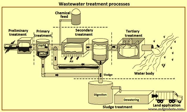
Gbr 1 Proses pengolahan air limbah
Perawatan awal
Tujuan dari perlakuan pendahuluan adalah menghilangkan material yang dapat menyebabkan penyumbatan, penyumbatan pada peralatan hilir dan abrasi peralatan. Pengolahan awal biasanya dilakukan sebelum air limbah dikirim ke ETP dan untuk meningkatkan kinerja ETP. Dalam pengolahan ini, padatan kasar dan material besar lainnya dari air limbah dihilangkan. Penghapusan bahan-bahan ini sangat penting untuk meningkatkan efisiensi operasional dan pemeliharaan unit perawatan berikutnya. Dalam pengolahan air limbah ini, sejumlah unit proses digunakan untuk menghilangkan karakteristik air limbah yang tidak diinginkan. Ini biasanya termasuk (i) pengendalian bau, dan (ii) operasi seperti pra-aerasi, penggilingan padat kasar, dan pemindahan material besar menggunakan saringan dan grates dll. Sering kali penghilangan minyak dan lemak serta pH koreksi juga dilakukan.
Perawatan primer
Ini adalah langkah pertama dalam proses pengolahan air limbah atau langkah kedua setelah perawatan pendahuluan. Perawatan primer mengikuti perawatan awal dan melibatkan perawatan fisik dan kimia untuk memperbaiki pH dari kondisi basa ke pH mendekati netralisasi, dan pengendapan fisik padatan tersuspensi dalam clarifiers primer untuk mengurangi beban BOD dan SS pada proses hilir. Secara keseluruhan, adopsi unit klarifikasi primer mewakili lebih sedikit masalah pada operasi proses biologis hilir. Misalnya, jumlah minyak dan lemak dan akumulasi biomassa yang lebih rendah dalam reaktor biologis, meminimalkan kemungkinan penurunan di dalam tangki dan mengurangi kecenderungan penggumpalan 'non-filamen' biomassa lumpur aktif, dll. Pengolahan primer dalam banyak kasus menggunakan koagulasi – proses flokulasi untuk meningkatkan pemisahan padatan.
Secara keseluruhan, adopsi unit klarifikasi primer mewakili lebih sedikit masalah pada operasi proses biologis hilir. Tujuan dari pengolahan primer adalah menghilangkan padatan organik dan anorganik yang dapat mengendap dengan sedimentasi dan menghilangkan bahan terapung dengan skimming. Selama perawatan primer sekitar 35% sampai 55% dari total BOD ke dalam, sekitar 55% sampai 75% dari total SS, dan sekitar 70% dari minyak dan lemak biasanya dihilangkan. Beberapa jumlah fosfor organik dan nitrogen organik serta logam berat yang terkait dengan padatan dihilangkan selama sedimentasi primer tetapi konstituen koloid dan terlarut tidak terpengaruh.
Selama pengolahan primer, pemisahan fisik padatan tersuspensi dari air limbah menggunakan clarifiers primer dilakukan. TSS dan tingkat BOD yang terkait dikurangi dalam proses pengolahan ini dan limbah disiapkan untuk langkah selanjutnya dari pengolahan air limbah. Penghapusan padatan organik dan anorganik yang dapat mengendap dengan sedimentasi dan skimming material adalah tujuan utama dari langkah perawatan ini.
Perawatan primer melibatkan berbagai proses fisiko-kimia dan memastikan kinerja yang memuaskan dari proses perawatan selanjutnya. Proses utama yang digunakan pada primary treatment adalah sedimentasi sedangkan proses bantu yang digunakan adalah fine screening dan flokulasi dan floatation. Flokulasi biasanya didahului dengan perlakuan kimia biasanya dengan kapur, tawas, atau bahan kimia berpemilik. Tujuan utama dari pengolahan ini adalah untuk menghilangkan logam dengan pengendapan dan juga untuk menghilangkan beberapa BOD koloid terkait untuk menghasilkan lumpur kimia. Perlakuan utama menerapkan proses koagulasi-flokulasi untuk meningkatkan pemisahan padatan. Beberapa dari proses ini dijelaskan di bawah ini.
Flokulasi – Ini adalah proses fisika-kimia yang membantu mendorong agregasi koloid kental dan zat tersuspensi yang dipisahkan secara halus dengan mencampur secara fisik dan dengan membantu koagulan kimia. Proses ini terdiri dari tangki pencampur cepat dan tangki flokulasi. Aliran air limbah bercampur dengan koagulan dalam tangki pencampuran cepat dan kemudian melewati bak flokulasi dan di bak flokulasi terjadi pencampuran limbah yang lambat yang memungkinkan partikel dikumpulkan dalam bentuk padatan yang lebih mudah mengendap dan lebih berat. Pencampuran yang lebih baik difasilitasi dengan bantuan udara yang menyebar atau dayung mekanis. Polimer organik alami, elektrolit anorganik, dan poli-elektrolit sintetis adalah berbagai jenis bahan kimia yang digunakan untuk koagulasi. Tergantung pada karakteristik dan sifat kimia dari kontaminan, bahan kimia tertentu dipilih.
Sedimentasi – Tujuan utama sedimentasi primer adalah untuk memungkinkan pemisahan fraksi fase padat dan cair dalam air limbah. Ini menghilangkan padatan yang mudah mengendap menggunakan gravitasi. Padatan terutama organik serta bahan mengambang seperti lemak, minyak, dan lemak. Padatan yang mengendap dikenal sebagai lumpur primer. Oleh karena itu, proses ini mengurangi kandungan SS dari air limbah influen. Meskipun volume lumpur primer hanya sekitar 2% dari total volume air limbah influen, volume tersebut membentuk sekitar 30% hingga 40% dari beban organik yang diterima (dinyatakan sebagai COD) dan sekitar 40% hingga 60% dari beban SS. Baffle dan skimmer minyak untuk menghilangkan gemuk dan padatan mengambang termasuk dalam ruang sedimentasi dan juga dapat ada scraper mekanis untuk menghilangkan lumpur dari bagian bawah ruang.
Efisiensi penghilangan padatan tergantung pada karakteristik tangki sedimentasi atau clarifier. Tangki sedimentasi adalah perangkat yang mencakup penyekat saluran masuk untuk pembuangan energi, zona diam untuk pengendapan partikulat, dan sarana mekanis untuk menghilangkan padatan yang mengendap, dan kecepatan aliran rendah ke saluran keluar.
Tangki flokulasi dan sedimentasi dapat berbentuk persegi panjang, lingkaran, atau pelat miring (Lamella), pemilihannya didasarkan pada kondisi lokasi setempat, area yang tersedia, dan pengalaman tim desain. Idealnya, dibutuhkan dua atau lebih tangki. Tangki persegi panjang dan Lamella menggunakan lebih sedikit lahan dibandingkan tangki melingkar dan berguna jika ketersediaan lahan lebih sedikit.
Tangki persegi panjang memiliki pola aliran lurus untuk meningkatkan flokulasi (dalam sedimentasi yang dibantu secara kimia) dan mengurangi waktu retensi. Air masuk di salah satu ujungnya, melewati pengaturan penyekat saluran masuk dan melintasi panjang tangki ke bendungan dan bak pembuangan. Mereka dirancang untuk memiliki rasio panjang:lebar 3:1 hingga 5:1 memberikan zona pengendapan efektif yang besar yang sangat mirip dengan kondisi ideal, dan kemiringan dasar 1%. Pengikis mekanis di bagian bawah bergerak mengumpulkan lumpur yang mengendap ke dalam zona pengumpulan. Lumpur kemudian dipompa keluar.
Dalam clarifiers melingkar (Gbr 2), pola alirannya adalah radial. Untuk mencapai pola aliran radial, air limbah dimasukkan dalam sebagian besar desain di tengah atau kadang di sekitar pinggiran tangki. Dalam desain pusat, air limbah diangkut melalui pipa dan penyekat pusat yang dikenal sebagai 'sumur tengah' dan mengalir secara radial menuju bendung yang mengelilingi lingkar tangki. Sumur tengah biasanya memiliki diameter antara 15% sampai 25% dari total diameter tangki dan tinggi 1 m sampai 2,5 m. Zona pengendapan diam harus cukup besar untuk memenuhi persyaratan laju luapan dan kedalaman untuk pengendapan diskrit dan flokulan.
Air yang telah diolah dialirkan melalui pelat bendung berlekuk-v. Lantai dibuat miring untuk membantu konsentrasi dan pembuangan lumpur. Lumpur dihilangkan menggunakan penggaruk mekanis. Waktu penahanan tipikal dalam tangki sedimentasi adalah 2 jam hingga 3 jam. Penghilangan padatan tersuspensi adalah 45% hingga 55%.
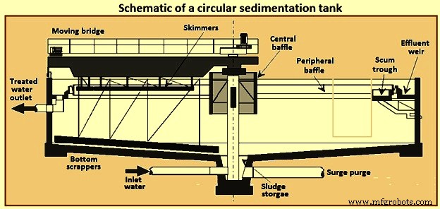
Gbr 2 Skema tangki sedimentasi melingkar
Flotasi udara terlarut – Gelembung udara digunakan dalam proses ini. Mereka diperlukan untuk menaikkan partikel tersuspensi dalam air limbah ke permukaan sehingga partikel tersuspensi dapat dengan mudah dikumpulkan dan dihilangkan. Gelembung udara yang masuk ke dalam air limbah terutama melekat pada partikel yang membantunya mengapung. Padatan tersuspensi, minyak terdispersi dan gemuk dari air limbah berminyak dan beberapa limbah lainnya dapat dihilangkan dengan proses flotasi udara terlarut (DAF).
Untuk menghilangkan minyak dan lemak, flotasi udara terlarut sangat cocok terutama di mana berat jenis padatan tersuspensi mendekati 1,0. Proses DAF menggunakan udara bertekanan untuk melepaskan gelembung udara mikro (berdiameter 10 mikrometer hingga 50 mikrometer) yang menempel pada partikel, sehingga memudahkan partikel minyak bebas untuk naik ke permukaan dan kemudian dihilangkan. Proses DAF sangat efektif dalam menghilangkan minyak dan lemak karena minyak tidak mengendap secara alami, memiliki berat jenis lebih kecil dari air. Ketika minyak hadir dalam bentuk emulsi, dibutuhkan bahan kimia untuk mengacaukan lapisan emulsi minyak.
The pressurized water flow can be the entire inflow of wastewater, part of the inlet flow, or water already treated by the process (effluent). This results in dissolved air flotation to be three types of usable process, called full flow, partial flow or recirculated flow respectively. Fig 3 shows a schematic of the DAF process. The most common DAF application for wastewater treatment is a recirculated flow system, as it needs less equipment for pressurization (lower energy consumption), it avoids pump abrasion problems, and prevents the formation of colloids and emulsions within the pumping system.
DAF process can reduce oil concentrations to 10 mg/litre to 25 mg/litre as long as the influent concentration is not greater than 500 mg/litre. DAF process operates at higher hydraulic loading rates than gravity sedimentation systems and hence detention times are shorter by 15 minutes to 30 minutes. This allows the DAF process to be more compact and has a smaller footprint. DAF process systems are available in circular or rectangular configurations.
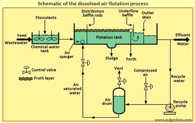
Fig 3 Schematic of the dissolved air flotation process
In retention tank the wastewater is pressurized and contacted with air. The super-saturated and pressurized water is passed through a pressure-reducing valve to the bottom of the floatation tank. The super-saturated air begins to come out in the form of fine bubbles from the solution, as and when the pressure starts releasing. The air bubbles attached with the suspended particles and trapped in sludge flock float over the surface and these floats are always swept from the surface and the mud is then collected from the bottom of the tank. The oil removal efficiency of the DAF process can be increased by the addition of certain coagulants.
Chemical treatment processes – The chemical treatment can be used, preferably before biological treatment as it removes the toxic chemicals which can kills the micro-organisms and or at any stage in the treatment process as and when it is necessary. Chemical treatment processes are described below.
Dissolved solids removal – Dissolved solids can be removed through a number of different methods namely (i) conversion to suspended materials, normally using chemicals to precipitate the contaminant as a solid or gas, to allow them to be removed by physical separation, (ii) adsorption onto a solid material, which can either be suspended or fixed as a bed, such as powdered or granular activated carbon, (iii) rejection using dense membrane processes, such as reverse osmosis or nano-filtration, or (iv) conversion to relatively innocuous end products.
Conversion necessarily involves chemistry or biochemistry, and the chemical reaction can be either reduction/oxidation (redox) or non-redox. Many chemical and biochemical processes operate by oxidation, the end products in the case of organic pollutants normally being carbon dioxide, nitrate and water. Examples of chemical reduction include the quenching of excess chlorine using bisulphite or the biochemical reduction of nitrate to nitrogen, the latter being referred to as ‘denitrification’. There also exist many important non-redox chemical processes, such as pH adjustment or precipitation of alkaline earth salts such as calcium carbonate or sulphate.
Neutralization – There is a wide range of pH of the untreated wastewater and it is not so easy to treat the wastewater with such type of varying range of the pH value. To optimize the treatment efficiency the neutralization process is used to adjust the pH value. To reduce the pH value sulphuric or hydrochloric acids can be added and to raise the pH value, dehydrated lime or sodium hydroxide alkalis can be added. Normally the process of neutralization is carried in a rapid mix holding tank or in a tank used for equalization. To control the pH of the discharge in order to meet the standards, the process of neutralization can be carried out at the end of the treatment.
Precipitation – The process of precipitation is carried out in two steps for the removal of the metal compounds from the stream of the wastewater. The mixing of precipitants with the wastewater and allowing a formation of the insoluble metal precipitants is the first step of the precipitation process. The removal of the precipitated metals from the wastewater through clarification and filtration is carried out in the second step and then the resulting sludge is being treated in a proper manner, and after treatment, it is recycled or disposed off. The important parameter to be considered in a chemical precipitation is pH controlling.
The solubility of metal hydroxides increases towards higher or lower pH and this is amphoteric in nature. Thus, for the precipitation of hydroxide for each metal, there is an optimum value of pH. As there is normally more than one metal in wastewater, hence, it is very much difficult to select the optimum treatment chemical and the pH control becomes more difficult and also it involves a transaction between the best possible removals of two or more metals. Lime, sodium hydroxide, soda ash, sodium sulphide and the ferrous sulphate are the various different chemicals used for the process of precipitation. The process for the effective removal of the metals like antimony, arsenic, chromium, copper, lead, nickel and zinc is normally the hydroxide precipitation and for removing mercury, lead, copper, silver, cadmium etc. sulphide precipitation is used. Fig 4 shows flow diagram of chemical treatment process for metal removal.
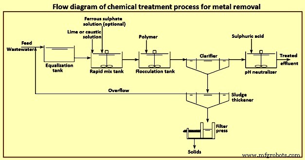
Fig 4 Flow diagram of chemical treatment process for metal removal
Secondary treatment
The secondary treatment process involves disintegration or decomposition of the suspended and dissolved organic substances present in the waste water using microorganisms. The activated sludge process (ASP) and the biological filtration methods are the mainly used biological treatment processes. The biological treatment process which is the mainly used for the secondary treatment process is based on the micro-biological action to decay the organic suspended and dissolved wastewater. The microbes can be used for the natural compound, both as a source of carbon sources and as an energy sources.
For removal of organic pollutants, the most efficient secondary treatment process is biological treatment. It primarily employs microbes naturally present in wastewater to break down organic contaminants. Some inorganic compounds like ammonia, cyanide, sulphide, sulphate and thio-cyanate are also biologically degradable. Biological processes can be broadly classified as (i) aerobic in which microbes which are used need oxygen to grow, (ii) anaerobic in which microbes which are used grow in the absence of oxygen but uses other compounds such as sulphate, phosphate or other organics present in the wastewater other than oxygen, and (iii) facultative in which microbes which are used can grow in the presence or absence of oxygen.
Aerobic processes consist of a biological reactor with a controlled amount of biomass and a clarifier for separation of the biomass from the final effluent. Aerobic processes need higher energy inputs and produce greater amounts of sludge compared to anaerobic systems. As an example, for the same 100 kg COD load entering the aerobic treatment plant, the energy needed is 100 kWh for aeration and produces 30 kg to 60 kg of sludge with the outlet effluent COD load of 2 kg to 10 kg. In the anaerobic treatment plant for the same 100 kg COD load, the sludge production is only 5 kg, or six to twelve times less, and produces 40 cum (cubic meter) to 45 cum of biogas which can be converted to produce 382 kWh of electricity. However, the outlet water COD is twice that of the aerobic plant, and hence of a lower quality.
Hydraulic retention time – It is the average time in the aeration basin equivalent to the volume of the basin divided by the average flow and expressed as hours. The hydraulic retention time is required to be sufficiently long to remove the prerequisite BOD and is dependent on the type of the biological treatment system. It can range from 0.5 hours to 120 hours. The lower the hydraulic retention time the quicker the wastewater reaches the outlet.
Mixed liquor suspended solids (MLSS) – Suspended solids level is one of the most important control parameters in biological wastewater treatment processes. It is not only directly related to sludge settling properties and effluent quality, but also related to food / micro-organism ratio which is in turn related with all aspects of sludge properties. MLSS represents the total suspended solids including bacteria, dead biomass, and higher life forms, irrespective of biological activity. The organic portion of MLSS is represented by ‘mixed liquor volatile suspended solids’ (MLVSS) which represents the biomass. MLSS is controlled by the sludge wasting rate. Typical MLSS are dependent on the process type. The more concentrated is the MLSS, the smaller is the equipment footprint and hence the popularity of membrane bioreactors (MBRs) in space constrained locations. MLVSS is 0.75 MLSS.
Food to microorganism (F/M) ratio – It is a term used for expressing the organic loading of an activated sludge process. F/M is a critical factor in process design and operation, especially in determining the aeration basin volume. F/M range is around 0.5 to 1.5. For conventional plants, F/M of 0.2 to 0.5 is aimed for. In biological treatment plants operating at high F/M loads (0.8 to 1.5), the rate of treatment increases at the cost of poor settlability of the sludge. Processes operating at low F/M loads (0.05 to 0.2) are associated with slow BOD removal rates but with good sludge settling. However, the system can be easily upset by a spike load of organics.
Sludge age – It is also known as ‘mean cell residence time’ (MCRT) and ‘solids retention time’ (SRT). It is calculated as the total quantity of sludge in the aeration tank and clarifier divided by the daily sludge losses through waste activated sludge and effluent. Sludge age can vary from 0.5 day to 75 days in low-growth rate systems. Sludge age is an indication of F/M ratios. Shorter times are indicative of high F/M ratios and longer times are indicative of low F/M ratios. Sludge age is expressed by the equation ‘sludge age =sludge mass in (aeration tank + clarifier) / daily sludge losses’.
The quality of sludge age can be determined using a microscope at 100x magnification. Daily microscopic analysis can prevent problems. Micro-organisms considered important in biological treatment are bacteria, fungi, algae, protozoa, rotifers, and worms. The presence of higher life form indicator organisms normally correlates to plant performance. They can indicate if the sludge is young, medium, or old. Good settling sludge is characterized by the presence of protozoa such as stalked ciliates and suctorians and normally is golden brown in colour (sewage treatment plants). Low sludge age is characterized by the absence of stalked ciliates and predominance of free swimming ciliates such as paramecium (these expend a lot of energy in swimming) and high BOD slugs by the absence of higher life forms. Old sludge is characterized by the presence of many worms (nematodes) or rotifers.
Another useful indicator is the ‘sludge volume index’ (SVI). Sludge is poured to a 1 litre graduated cylinder and the percentage of settled sludge in 5 minute intervals is noted for 30 minutes. SVI is expressed in ml/g. It is a reliable troubleshooting test. SVI values can vary from 30 ml/g to 400 ml/g. Values below 150 indicate good sludge settling and above this indicate sludge bulking. Other key variables which affect the operation of the biological reactor are given below.
Oxygen requirement – Oxygen is needed for the decomposition of organic matter. The concentration depends on organic matter consumption, endogenous respiration demand and total nitrification of TKN (total Kjeldahl nitrogen) oxidation. Typical oxygen concentration in an aeration tank is 2 mg/l to 4 mg/l. The higher values are maintained for nitrogen removal. Above this, electricity is wasted.
Sludge production (sludge yield) – The decay of biomass produces sludge. For conventional industrial systems, sludge production can be as low as 0.15 kg / kg BOD, such as in coke making.
Sludge recirculation rate – A portion of the sludge produced is recirculated to promote the production of more sludge in the aeration tank. It is the ratio between the sludge recirculation volumetric flow and treatment volumetric inflow. In any case, the capacity of the sludge recirculation system is not to be less than 200 % of the daily average total inflow.
Nutrient requirements (C:N:P ratio) – Besides carbon, hydrogen, and oxygen biomass needs nitrogen, phosphorous, and micro-nutrients such as iron, calcium, magnesium, copper, zinc and so on. Most industrial wastewaters lack N and P which is to be added (in the form of urea, super-phosphate or ammonium phosphate) to maintain optimal microbial growth conditions. The minimum C:N:P ratio needed for optimal microbial growth in the in aerobic processes is 100:5:1, and anaerobic processes is 330:5:1.
The most common biological processes are described briefly below.
Aerobic processes – activated sludge process – Biological processes, employing aerobic biomass in suspension, have traditionally been known as activated sludge processes. The ASP was developed in the United Kingdom in the early 1900s for the treatment of the domestic sewage and it has since been adapted for removing biodegradable organics in industrial wastewater. The ASP and its variants are capable of treating biodegradable wastewater of moderate strength (10 mg/l to 1,000 mg/l BOD) to high strength (greater than 1,000 mg/l BOD). The ASP does not remove heavy metals or TDS. Some contaminants such as cyanide, and heavy metals such as chromium and mercury, present in the wastewater act as inhibitors for the proper functioning of the ASP as well as other biological processes. ASPs have been categorized, according to the mass loading design, in three groups namely (i) low load activated sludge (extended aeration, oxidation ditches, etc.), (ii) medium load (or conventional), and (iii) high loading.
The ASP involves blending settled primary wastewater or equalized influent with a culture of micro-organisms into a fluid called ‘mixed liquor’. This mixed liquor is passed through an aeration tank which provides an adequate oxygen rich environment for the microbes to eat and stabilize the organic matter in water. Mixing brings oxygen and food to micro-organisms allowing the micro-organisms to clump together whilst preventing floc settling in the aeration tank. The process produces ‘waste activated sludge’ (WAS) consisting of microbes and excess microbial matter. The solids and treated wastewater are separated in a secondary clarifier or other solids separation step such as a membrane bioreactor (MBR). Here the majority of the WAS is returned to the aeration tank as returned activated sludge (RAS) to maintain the microbial population in the aeration tank, as well as ensuring that the activated sludge is old enough to degrade COD and aromatic hydrocarbons. The remainder is removed and undergoes thickening.
The secondary clarifier has the dual purpose of clarifying the wastewater as well as concentrating the sludge. The process is sensitive to pH fluctuations, where a high or low pH can upset the system and cause overloading of the clarifier. Fig 5 shows a schematic of the activated sludge process and membrane bioreactor process.
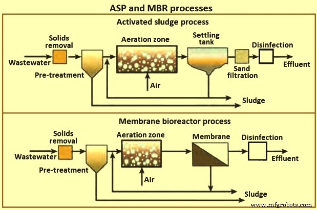
Fig 5 ASP and MBR processes
Nitrogen containing compounds are toxic to aquatic life, deplete oxygen in the receiving waters, adversely affect public health and reduce the potential for water reuse. Hence, nitrogen containing compounds are removed, if deemed excessive, by nitrification and then denitrification processes. Organic nitrogen is converted to ammonia, then converted to nitrite, which is further oxidized to nitrate and finally to gaseous nitrogen. Denitrification consumes alkalinity and needs to be sufficient so as not to depress the pH. It requires 7.14 mg/l of bicarbonate alkalinity for each 1 mg/l of ammonia nitrogen removed. Oxygen also needs to be maintained at concentrations closer to 4 mg/l for denitrification. The process control is normally customized for each effluent treatment system depending on wastewater characteristics and for optimal operation.
Aerobic processes – oxidation ditch process – This process which has been developed in the 1950s in the Netherlands, is a variant of the ASP and is a special form of extended aeration. The shape of the oxidation ditch is like a ring. Wastewater, micro-organisms and activated sludge is mixed in a continuous loop ditch in order to complete nitrification and denitrification reactions. The oxidation equipment consists of ditch body, aeration mixers and inlet and outlets. Given its long hydraulic retention time of 20 hours to 36 hours, low organic loading and long sludge age compared to conventional ASP, equalization, primary sedimentation, and sludge digestion tanks are omitted.
Oxidation ditch has many advantages in that it provides (i) low energy consumption, (ii) low maintenance, (iii) ease of operation, low capital expenditure, (iv) less sludge due to long extended solids retention time, and (v) resistance to shock loads and hydraulic surges due to long hydraulic retention time. The disadvantages are that the effluent suspended solid quality is inferior to the ASP process and needs a large land area.
Aerobic processes – sequencing batch reactor – The sequencing batch reactor (SBR) process differs from the other ASPs. It is a batch process. The principle is that all of the process steps of ASP, i.e. primary settling, biological oxidation and secondary settling take place in a single tank. The process steps are filling, react, settle, draw, and idle. SBR is compact and has low capital expenditure. It is used when land area is scarce since it needs only one tank to fulfill the aeration and clarification steps. It is also used to treat nitrogen and phosphorous. Standard cycles are normally 4 hour to 6 hours long, resulting in 4 to 6 reaction cycles per day. Compared to the conventional ASP, it is resistant to shock loading, flexible operation due to adjustment of run time and low sludge production.
Trickling filters – These filters, developed in the 1890s, are an example of a fixed film biological process compared to the ASP which is a suspended process. A trickling filter consists of bed of coarse material, such as rounded rocks (25 mm to 100 mm in diameter), crushed stone, wooden or plastic slats and plastic rings over which wastewater is discharged from moving spray distributors or fixed nozzles. The filter media provides a large amount of surface area for the micro-organisms to cling and grow a jelly like bio-film of around 10 mm thickness. In the outer portions of the bio-film (0.1 mm to 0.2 mm) the aerobic bacteria break down the organic matter. When the bio-film becomes very thick it falls off and a new bio-film layer forms. Modern trickling filters use plastic media over rocks since they weigh less and because of it, filter media can be upto 6 m in depth compared to 3 m in depth for rock filters, allowing taller filters using less land area.
The filter effluent is recycled to minimize drying of the filter media, improve filter efficiency, and reduce odour potential. Sometimes, two filters are assembled in series to handle strong wastewater. The sprays rotate at 2 revolutions per minute (rpm) to 5 rpm and a typical wetting rate is 0.6 cum/hour to 2.4 cum /hour. When the wetting rate is too low, the water does not penetrate the depth of the filter bed uniformly causing channeling and acts as an incubator for flies, as well as creating odour problems. Low rate filters operate on natural ventilation, whereas high rate filters require forced draft fans to provide adequate ventilation.
The trickling filter is followed by a secondary clarifier. Trickling filters are classified according to the organic and hydraulic loads such as low rate, intermediate, high rate, roughing filter and super high rate. The advantages of a trickling filter are (i) lower energy requirements than ASPs, (ii) simple operation with no issues of MLSS inventory control and sludge wasting, (iii) better recovery from shock toxic loads, (iv) no problems of bulking sludge in secondary clarifiers, (v) compact and suitable for place where land is scarce, (vi) less equipment maintenance needs, effective in treating high concentration of organics dependent on type of media used, and (vii) better sludge thickening properties. The disadvantages are organic loading levels, that the effluent water quality (in terms of BOD and TSS) is lower than ASP and can need further treatment, odour problems, flies, prone to plugging of filter media and at low temperatures natural ventilation systems do not operate that well.
Moving bed bioreactor – Moving bed bioreactor (MBBR) was developed in the 1980s by Kaldnes in Scandinavia. The MBBR process is a more modern fixed film process in which the micro-organisms grow on plastic media. The media are made from high density polyethylene or polypropylene with a diameter of 13 mm to 25 mm, and hence have a large surface area which helps the biomass to grow inside the surface and are in constant motion due to the compressed air which is blown from under the tank. The process has been applied in a variety of industrial wastewater treatment applications in aerobic and anaerobic modes with or without denitrification depending on the mode of mixing.
Benefits of MBBR are that it is good for high organic loading applications, improved settling characteristics, no need for sludge recirculation from secondary clarifier thereby making it a ‘once through’ process, compact and low footprint compared to the ASP process and has modular construction. It can also retrofit existing ASP systems, needs fewer operational controls than ASPs, and contains fewer mechanical and instrumentation controls compared to a MBR system. A typical hydraulic retention time for MBBR is 2 hours to 3 hours, compared to 12 hours to 24 hours for ASPs. Disadvantages of MBBRs compared to the ASP are that it needs a higher oxygen concentration, the need for improved influent wastewater screening, and additional hydraulic profile head losses due to flow through the media screening devices.
Membrane bioreactor – Though external membrane bioreactors were originally developed in the 1960s, they became popular only after the development of the immersed (submerged) MBRs in the late 1980s. The lower operating cost of the submerged MBR configuration and the decreasing cost of the membranes have made MBRs a popular choice for domestic and industrial wastewater treatment. MBRs are used for industrial wastes with BOD of 5,000 mg/l to 40,000 mg/l with BOD ranges of 200 mg/l to 600 mg/l. Fig 6 shows the principle of membrane bioreactor.
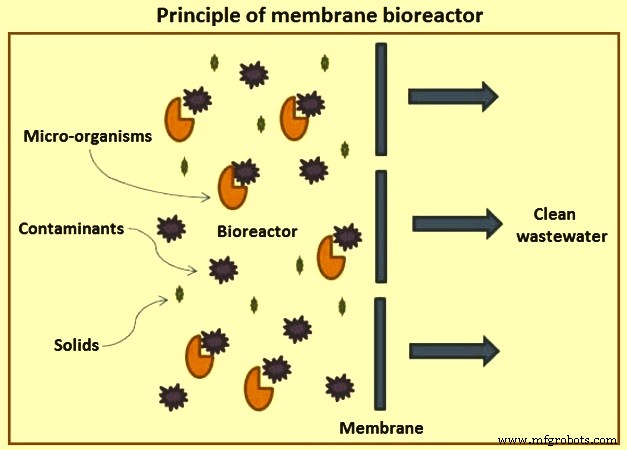
Fig 6 Principle of membrane bioreactor
The quality of the final effluent from a conventional ASP unit is highly dependent on the hydrodynamic conditions in the clarifier and settling characteristics of the sludge. This leads to variable performance. As a result, large clarifiers are needed with long residence times. The MBR process was developed to remove these disadvantages of conventional ASPs.
MBRs are a hybrid with two interdependent treatment processes:biological treatment and membrane treatment (Fig 5). It is similar to a conventional ASP in that both have mixed liquor solids in suspension in an aeration tank. The difference in the two processes lies in the method of separation of bio-solids. In the MBR process, the membranes create a solid barrier to bio-solids based on micro-filtration (MF) with a pore size of 0.6 micrometers, or ultra-filtration with a pore size of 0. 04 micrometers, and hence are not subject to gravity settling characteristics of the solids. Thus, a MBR unit brings aeration, clarification, and filtration in a single step with MLSS concentrations reaching 20,000 mg/l or higher resulting in a smaller footprint than conventional ASP units.
MBRs provide a final effluent quality independent of sludge conditions with higher removal of organics and persistent pollutants, and nutrients with COD removal of 98 % and suspended solids removal efficiency of 100 %. The high quality effluent produced is ideal for reuse applications. Another feature of MBRs is the long sludge age. However, this also contributes to fouling of membranes. Moreover, MBR units can be installed directly to a reverse osmosis (RO) plant, bypassing the need for an ion exchange or other equipment to protect a membrane plant provided the hardness or scaling compounds are not excessive.
There are two types of MBR configurations namely immersed and side-stream. Immersed systems are more common in large industrial units, whereas side-stream is limited to smaller units. There are also differences in the membrane employed from hollow fibre, flat plate, and tubular. Immersed MBRs use hollow fibre or flat plate whereas tubular membranes are used in side-stream MBRs. MBR produces an equivalent treatment level to an activated sludge process followed by micro-filtration or ultra-filtration.
Despite the advantages of MBRs, there are still challenges in using MBRs in industrial applications. The advantages of MBR are (i) 25 % lower footprint, (ii) replaces the clarifier and gravity filter of conventional systems, (iii) ideal for land constrained sites and lower hydraulic retention time of 4 hours to 8 hours. MBR provides impermeable barrier for solids producing highest quality effluent with BOD less than 5 mg/l and turbidity of less than 0.1 NTU (Nephelometric turbidity unit). Membrane fouling is one of the major challenges which results in reduced performance and frequent cleaning or membrane replacement leading to increased maintenance and operating costs. All MBRs require a minimum of fine screens of 3 mm. Sludge produced can be difficult to dewater. Sludge retention time is independent of hydraulic retention time. High sludge age of 15 days to 140 days can be obtained. It has modular expandability, less odour, and flexible operation with less susceptible to upsets. The process can be automated.
Secondary clarifiers – The purpose of the clarifier is twofold. One is to thicken the solids after biological treatment and then settle them out. The second is to produce a clear effluent of the settled solids. Clarifiers in activated sludge systems are to be designed not only for hydraulic overflow rates, but also for solids loading rates. This is because both clarification and thickening are needed in activated sludge clarifiers. Of the process variables the most important is sludge age or mean cell residence time. Another important control parameter is the solids loading rate which is defined as the required surface for suitable sludge thickening in the bottom of the unit (compression zone). The clarifiers are either of rectangular design or of circular design.
Tertiary treatment
Conventional secondary treatment frequently is not sufficient to meet the required effluent quality standards to discharge water to surface water bodies. The effluents can need tertiary processes so as to complete solids and organic matter removal, for colour reduction or recalcitrant compounds degradation, nutrient reduction, and disinfection. The persistent contaminants which the secondary treatment is not able to remove are removed by the tertiary treatment process. These processes are classified as ‘tertiary treatments’, as they are installed after secondary treatment, but some of them, like oxidation processes, can be also placed before biological treatment to improve the bio-degradability of recalcitrant compounds.
Before the treated wastewater is reused, recycled, or discharged to the environment, the tertiary treatment process is used as a final cleaning process cleaning process to improve the quality of the wastewater. For the removal of nutrient (nitrogen and phosphorus), removal of toxin [pesticides, VOC &metals], and for the polishing of the effluent like BOD &TSS, the tertiary treatment processes are used. These processes are the extension of conventional secondary biological treatment process for the further stabilization of the substances which demands oxygen in the wastewater, and also to remove the nitrogen and phosphorus.
The physical and chemical separation techniques like activated carbon adsorption, flocculation or precipitation are the process involved in the tertiary treatments. The most common tertiary treatment applications are filtration and disinfection and where applicable ammonia and phosphorous removal. Ammonia is toxic to fish and phosphorous causes algal blooms.
Filtration – Filtration is a separation process which consists in passing a solid–liquid mixture through a porous material (filter media) which retains the solids and allows the liquid filtrate to pass through. Granular media polishing filters are used the removal of suspended solids for the removal of suspended solids in the 5 mg/l to 50 mg/L range. The most common filters are the multimedia filters. The quality of the filtrate depends on the size, surface charge, and geometry of both suspended solids and filter media, as well as on the water analysis and operational parameters. Based on media filters can be categorized as (i) single media (sand or anthracite), (ii) dual media (sand and anthracite), and (iii) multimedia (garnet, sand, and anthracite).
The most common filter media in water treatment are sand and anthracite. The effective grain size for fine sand filter is in the range of 0.35 mm to 0.5 mm, and 0.7 mm to 0.8 mm for anthracite filter. In comparison to single sand filter media, dual filter media with anthracite over sand permit more penetration of the suspended matter into the filter bed, thus resulting in more efficient filtration and longer runs between cleaning. The design depth of the filter media is a minimum of 0.8 m. In the dual filter media, the filters are normally filled with 0.5 m of sand covered with 0.3 m of anthracite.
In industrial applications, filters are housed in steel pressure vessels where the interior is epoxy coated, with interior manifolds for distribution of water and an under drain system for collection of filtrate and backwashing.
As the filter vessel for pressure filtration is designed for pressurization, a higher-pressure drop can be applied for higher filter beds and / or smaller filter grains and / or higher filtration velocities. The design filtration flow rates are normally 10 m/h to 20 m/h and the backwash rates are in the range of 40 m/h to 50 m/h. The available pressure is normally about 2 bars to more than 4 bars.
For feed waters with a high fouling potential, flow rates of less than 10 m/h and / or second pass media filtration are preferred. If the flow rate has to be increased to compensate for one filter which goes out of service, the flow rate increase is to be gradual and slow to prevent the release of previously deposited particles.
During operation, influent water to be filtered enters at the top of the filter, percolates through the filter bed, and is drawn off through the collector system at the bottom. Periodically, when the differential pressure increase between the inlet and outlet of the pressure filter is 0.3 bars to 0.6 bars, the filter is backwashed and rinsed to carry away the deposited matter. Backwash time is normally about 10 minutes. Before a backwashed filter is placed back into service, it is to be rinsed to drain until the filtrate meets the specification. Backwash rates when excessive leads to loss of filter media.
Variations of the deep rate filtration are high rate filtration which operates at much faster inlet flow rates. Aside from media filters, other types of filters are disc filters and cartridge filters. These are also used to protect membrane filtration systems. Disc filters made from pleated cloth media have very high flow rates and a small footprint, producing very high quality water suitable for reuse applications and do not need extensive backwashing.
Some advanced water treatment processes are also used as the tertiary treatment. These processes are applied to the conventional treated wastewater to improve the quality upto a degree suitable for various applications of recycle and reuse including the potable reuse. The additional tertiary treatment processes are different membrane treatment processes like micro-filtration, ultra filtration, nano-filtration, other processes like reverse osmosis, advanced oxidation processes, and additional disinfection processes like ozonation and the use of ultraviolet radiation. Some of these advanced processes are described below.
Membrane technology – Membranes are a popular choice for water reuse applications since their advent in the 1960s. Costs of membrane systems have reduced dramatically and, coupled with technological advances in membrane design, membrane options and operating limits, the range of applications in water and wastewater treatment is increasing rapidly. In pressure driven membrane filtration, membranes separate the components of a fluid under pressure. The membrane pores, being extremely small, allow the selective passage of solutes. The popularity of membrane processes arises from the fact that they are effective in the removal of both dissolved and suspended solids. A wide range of materials like cellulose acetate, polyamides, poly- sulfones, poly-propylene, nylon, poly-acrylonitrile, poly-carbonate, polyvinyl alcohol, poly-tetra-fluoro-ethylene, ceramic, and metal composites are basically used to produce the membranes. The membrane pore size is the parameter for the degree of selectivity of a membrane. On the basis of the pore size, there are four types of pressure driven membranes. Micro-filtration and ultra-filtration are low pressure applications given their larger pore size. Nano-filtration needs medium pressure, and ‘reverse osmosis, given the smaller pore size, needs significant pressure to push the solute through the membrane.
Advanced oxidation processes – Advanced oxidation processes (AOPs) are defined as processes which involve generation and use of powerful but relatively non-selective hydroxyl radicals in sufficient quantities to be able to oxidize the majority of the complex chemicals present in the effluent water. The AOPs show specific advantages over conventional treatment alternatives since they can eliminate non-biodegradable organic components and avoid the need to dispose of residual sludge. After fluorine ([V (volts) =-3.06], hydroxyl free radicals (OH-) have the highest oxidation potential (V =-2.86). In the AOP process, OH – radicals are generated which in turn react with organic molecules to generate CO2 and water. AOPs can be classified into two groups, non-photochemical AOPs and photochemical AOPs. Photochemical means a light source is needed. Normally ultra violet (UV) light is used as the photo-chemical source. Low pressure UV lamps have a wavelength of 254 nm. Maximum ozone absorption takes place at a wavelength of 253.7 nm. Of the non-photo-chemical technologies, those most prevalent in the treatment are Ozonation, Ozone/ (H2O2) and Fenton’s reaction.
Ozonation – Discovered in 1785, Ozone (O3) is a widely applied strong oxidizing agent (-2.07V) for disinfection of potable water and wastewater, decolourization, odour removal, organics degradation and cyanide destruction, etc. O3 at room temperature is a bluish pungent gas, sparingly soluble in water, highly corrosive, toxic and explosive when the concentrations in air exceed 20 %. As a germicide, it is 3,125 times faster than chlorine. Ozonation efficacy is increased with high pH and temperature. When O3 dissolves in water or wastewater it can remain as the O3 molecule (at pH more than 7 and slower reaction) or decompose (pH more than 8) producing the hydroxyl free radical (OH-) which is a 35 % stronger oxidizing agent than O3. Both reactions occur simultaneously and hence reaction kinetics strongly depends on the characteristics of the treated wastewater (e.g. pH, organic concentrations, presence of foaming agents and surfactants, ozone concentration and temperature, etc.). A pH of 8 to 10 is most suitable for oxidation of organic compounds. Ozone is sparingly soluble in water and rapidly decreases with increasing temperature. At a temperature of 20 deg C, 100 % ozone solubility in water is 570 mg/l. The preferred temperature ranges from 25 deg C to 50 deg C.
A simplified reaction mechanism of ozone at a high pH is given by the equation 3 O3 + H2O =2OH radical + 4 O2. Molecular O3 is a very selective oxidant. It only reacts with certain compounds and for this reason it can be applied in low dosages for industrial wastewater applications. It can also inhibit or destroy the foaming properties of residual surfactants as well as oxidizing a good portion of the COD. Thus, O3 improves the overall biodegradability of the effluent by converting recalcitrant compounds to easily digestible compounds and can be applied upstream or downstream of a biological treatment plant. The residual oxygen in the vent gas can be recycled back to the secondary biological treatment plant, reducing aeration requirements. Another advantage is that it does not increase sludge mass.
O3 can be applied in the gaseous form and because of its unstable nature it needs to be generated on-site from air or pure oxygen using UV radiation, electrochemistry or corona discharge generators. O3 leak detectors are to be installed to give audible and visible warnings and shut down the generators in the event of a leak. O3 is deactivated in the presence of high concentration of salts. A variation of this process is the O3/H2O2 process. Developed to reduce the O3 concentrations, the H2O2 acts as a catalyst enhancing the capability of O3 to produce more OH radicals. At a low pH, H2O2 reacts very slowly with O3 and at a high pH (alkaline conditions) reacts rapidly.


