Teknologi dan Sistem Pembersihan Gas Buang
Teknologi dan Sistem Pembersihan Gas Buang
Pencemaran lingkungan adalah salah satu masalah terbesar di seluruh dunia saat ini. Dari serangkaian permasalahan lingkungan global, kini semakin banyak orang yang menyadari bahwa lingkungan dan sumber daya merupakan kebutuhan dasar bagi kelangsungan hidup dan perkembangan umat manusia. Gas buang yang merupakan produk dari sebagian besar proses teknologi tercemar dengan berbagai partikel padat. Untuk menggunakan gas lebih lanjut (jika memiliki nilai kalor yang cukup) atau untuk melepaskannya ke atmosfer, perlu untuk membersihkan gas. Namun, pengendalian emisi atmosfer membutuhkan biaya, dengan sedikit pengembalian finansial kepada organisasi pengoperasi.
Beberapa tahun terakhir telah terlihat perubahan total dalam sikap, pendidikan, tanggung jawab, dan peraturan di bidang pengendalian emisi di berbagai negara. Regulasi pengendalian emisi semakin ketat seiring berjalannya waktu dalam upaya menyelamatkan generasi mendatang dari dampak buruk polusi atmosfer. Sekarang beberapa organisasi dengan cepat mengubah sikap mereka terhadap polusi atmosfer dan terlibat secara proaktif dalam kegiatan pengendalian polusi. Organisasi sekarang ingin dilihat oleh publik sebagai organisasi yang bertanggung jawab yang menghasilkan produk 'bersih'. Ini sebagian didorong oleh pasar, karena pasar sekarang menuntut semakin banyak produk 'bersih'. Pelanggan dalam situasi sekarang ini semakin teredukasi, baik dalam tanggung jawab mereka terhadap lingkungan, maupun dalam manfaat memiliki lingkungan yang bersih.
Tujuan dari sistem pembersihan gas buang adalah untuk mengurangi emisi atmosfer dari zat yang berbahaya bagi lingkungan dan kesehatan. Ini termasuk misalnya logam berat, dioksin dan zat yang menyebabkan pengasaman dan eutrofikasi. Karena beberapa zat dalam gas buang bersifat toksik dan karsinogenik, penting untuk mengurangi emisinya. Pengasaman hutan dan danau telah dikurangi secara substansial dengan menghilangkan oksida belerang dan nitrogen dari gas buang.
Proses teknologi pembangkit listrik metalurgi, kimia, dan termal menghasilkan gas buang limbah yang biasanya sarat dengan debu dan pada suhu tinggi. Komposisi dan kuantitas gas-gas ini tergantung pada sifat proses teknologi dan bahan bakunya. Emisi gas buang limbah sebenarnya merupakan hasil dari bahan baku yang digunakan, serta proses dan reaksi yang berlangsung di pabrik tersebut. Gas buang dapat mengandung karbon dioksida, karbon mono oksida, oksida belerang (SO2 dan SO3) dan nitrogen (NOx), hidrogen, hidrogen sulfida (H2S), fluor (dalam bentuk HF), klorin (dalam bentuk HCl). ), arsenik, merkuri, senyawa organik volatil (VOC), uap air, dan debu, dll. Uap air tidak berbahaya tetapi berkontribusi pada gumpalan yang terlihat di outlet cerobong.
Ada beberapa proses teknologi yang berlangsung pada suhu tinggi. Selanjutnya banyak dari proses ini menangani bahan baku beberapa di antaranya dalam bentuk denda. Oleh karena itu semua proses ini rentan untuk memancarkan gas polutan dan partikel ke atmosfer. Hal ini pada gilirannya mempengaruhi kualitas udara di sekitar pabrik. Untuk meningkatkan dan melindungi kualitas udara, berbagai perangkat pengendalian polusi digunakan untuk pengurangan emisi. Sebelumnya selama bertahun-tahun, peralatan pengendalian polusi hanya digunakan untuk proses-proses di mana jumlah polutannya sangat tinggi atau bersifat racun. Peralatan ini juga sebelumnya digunakan di mana mereka memiliki beberapa nilai pemulihan. Namun dalam skenario saat ini, dengan peraturan lingkungan yang semakin ketat dan dengan meningkatnya kepedulian masyarakat terhadap lingkungan, menjadi penting untuk melihat emisi dari semua proses teknologi dan memasang peralatan di semua area untuk mengurangi emisi ke tingkat seminimal mungkin.
Setidaknya ada lima kelompok utama sumber polusi atmosfer yang biasanya dikaitkan dengan proses teknologi, masing-masing dengan teknologi praktik terbaik khusus untuk pengurangannya. Pengelompokan tesis bukan merupakan daftar yang komprehensif karena di mana konsentrasi gas asam yang kuat ditemui; teknologi pembersihan gas buang alternatif yang akan diterapkan seperti pabrik asam sulfat. Lima pengelompokan utama untuk teknologi pembersihan gas ini terkait dengan (i) kontrol emisi debu dan partikulat, (ii) gas asam seperti kontrol SO2 / HCl dan HF, (iii) kontrol pengurangan NOx, (iv) kabut asam dan aerosol lainnya kontrol, dan (v) kontrol merkuri, dioksin/furan dan VOC. Untuk teknologi fiksasi gas asam, pembuangan produk seperti biasa tetap menjadi tantangan. Di sebagian besar aplikasi, produk limbah hanya diisi dengan biaya operasi yang diperlukan yang menyertainya. Peralatan pengontrol emisi untuk kelima kelompok teknologi pembersihan gas ini pada dasarnya terdiri dari dua jenis (i) peralatan kontrol emisi debu dan partikulat dan (ii) peralatan kontrol emisi gas. Artikel ini berkonsentrasi pada sistem kontrol emisi debu dan partikulat.
Masalah pembersihan gas suhu tinggi secara umum adalah salah satu yang mungkin paling membingungkan bagi industri. Sulit karena masalahnya biasanya terkait dengan partikel yang sangat halus yang terdispersi dalam gas pada suhu yang dapat berkisar dari 700 derajat C sampai 1.500 derajat C. Dalam beberapa kasus bahkan suhu yang lebih tinggi dapat terlibat. Karena aerosol halus dan suhu tinggi yang terlibat, pendekatan biasa biasanya tidak menyelesaikan masalah. Oleh karena itu, kemajuan di bidang ini tidak secepat itu. Masalah dasar yang terkait dengan pembersihan gas suhu tinggi adalah masalah ekonomi dan persyaratan mendasar untuk pembersihan.
Dalam beberapa kasus pembersihan gas buangan diperlukan karena merupakan bahan yang bernilai penting atau, jika bahan partikulat dihilangkan, sisa gas yang mudah terbakar dan diperoleh kembali dalam bentuk panas atau energi yang dapat digunakan dalam proses. Dalam kasus lain, nilai ekonomi dari efluen, baik partikulat, gas, atau kombinasi biasa, sangat kecil sehingga biaya pembuangan merupakan masalah yang cukup besar. Dalam kasus ini, pembersihan atau pemindahan yang diperlukan untuk mencegah polusi udara adalah tindakan yang hanya ada pengembalian tidak berwujud.
Pada kategori kedua, keinginan industri adalah memperoleh pembersihan dengan biaya minimal tanpa membebani beban berupa peningkatan biaya produksi. Biaya untuk mencegah polusi udara masyarakat dan kemungkinan cedera pada properti atau publik biasanya tanpa pemulihan nyata selain hubungan masyarakat yang baik.
Pembersihan yang efektif dari gas-gas ini menimbulkan masalah teknis yang serius karena berbagai kotoran. Sistem pembersihan gas dengan efisiensi tinggi sangat penting untuk operasi yang andal dan masa pakai yang lama dari pembangkit listrik metalurgi dan termal suhu tinggi, dan memungkinkan operator untuk memenuhi standar pengendalian polusi yang relevan. Pemilihan instalasi pendingin dan pembersihan gas sangat penting sehubungan dengan kelayakan teknis, penerimaan ekonomi, dan kompatibilitas lingkungan. Selanjutnya, sistem pembersihan gas harus dirancang untuk mencapai tingkat efisiensi, keamanan, dan keandalan pembersihan tertinggi sekaligus memberikan perlindungan lingkungan terbaik.
Kriteria penting untuk desain sistem pembersihan gas adalah (i) volume gas dalam N cum per jam, (ii) komposisi kimia gas, (iii) kadar air gas, (iv) suhu gas, (v ) kandungan debu gas dalam kg per jam, (vi) karakteristik debu, seperti korosif, abrasif dll., (vii) kisaran ukuran partikel debu, (viii) standar emisi, (ix) karakteristik ledakan gas , (x) desain higienis, (xi) sistem on line atau off line, dan (xii) bahan konstruksi.
Ada tiga pertimbangan utama dalam desain sistem pembersihan gas. Yang pertama adalah tudung yang dirancang untuk menangkap debu dan gas yang dikeluarkan dan mencegah area kerja yang dipenuhi asap. Yang kedua adalah bahwa gas dan debu yang tertangkap oleh kap mesin harus dibersihkan sebelum dilepaskan ke atmosfer. Ketiga, debu yang terkumpul harus dibuang sedemikian rupa sehingga tidak terbawa kembali ke udara atau sungai sehingga menjadi masalah polusi lagi.
Gas buang yang berasal dari tungku metalurgi seringkali memiliki suhu tinggi (700 derajat C hingga 1.500 derajat C atau bahkan lebih tinggi) dan kandungan debu yang tinggi. Oleh karena itu, sebelum mengolah gas-gas ini dalam sistem pembersihan gas, gas-gas ini harus didinginkan hingga suhu di bawah 400 derajat C. Beberapa metode pendinginan gas digunakan dalam praktik. Ini adalah (i) boiler panas limbah, (ii) pendinginan tidak langsung dengan udara, (iii) pendinginan tidak langsung dengan air, dan (iv) pendinginan evaporatif dengan air.
Boiler panas limbah terutama digunakan untuk mendinginkan gas buang dari proses teknologi yang menghasilkan gas buang dengan laju aliran gas terus menerus. Hal ini memungkinkan penerapan pendinginan gas menggunakan boiler panas limbah dengan hasil operasi yang baik.
Sistem pendinginan gas dengan pendinginan tidak langsung dengan udara relatif jarang digunakan dalam praktek karena beberapa kelemahan seperti (i) pendinginan udara memiliki suhu yang lebih rendah dari titik embun gas proses, dan kondensasi asam terjadi pada dinding pendingin yang menyebabkan korosi pada peralatan, (ii) risiko akresi dan penyumbatan karena debu yang lengket, (iii) waktu retensi gas pada suhu tinggi (lebih tinggi dari 550 derajat C) yang lama yang menyebabkan terbentuknya tambahan SO3 dan menaikkan titik embun gas, dan (iv) jika laju aliran gas berfluktuasi, sulit untuk mengontrol suhu keluar gas.
Sistem pendinginan gas dengan pendinginan tidak langsung dengan air sering digunakan. Dalam hal ini, saluran cerobong memiliki tabung air di sekelilingnya yang melaluinya air pendingin mengalir. Ukuran tabung dan parameter air (tekanan dan aliran) harus sedemikian rupa sehingga suhu air yang dipanaskan selalu tetap di bawah tingkat penguapannya. Sementara sistem menghindari uap dan masalah peraturan yang terkait dengan penanganan uap, kelemahan sistem berkaitan dengan peralatan yang lebih besar dan penanganan volume air pendingin yang lebih besar.
Pendinginan evaporatif dengan air adalah alternatif teknis yang cocok untuk pendingin udara tidak langsung atau boiler panas limbah untuk mendinginkan gas dengan laju aliran gas yang berfluktuasi. Peralatan pendinginan evaporatif modern menggunakan jenis khusus dari nozel semprot, yang disebut nozel dua komponen (air dan udara bertekanan), yang memungkinkan operasi yang fleksibel dan pengendalian sensitif suhu gas di outlet pendingin. Fitur ini sangat penting untuk menghindari penurunan suhu gas yang berlebihan yang dapat menyebabkan kondensasi kabut asam dan sebagai akibatnya pembasahan debu dan pembentukan endapan debu basah, pada presipitator gas panas berikutnya serta korosi. Keuntungan menggunakan pendingin evaporatif adalah (i) pendinginan evaporatif mengurangi pembentukan SO3 tambahan dalam gas karena waktu retensi gas yang singkat di bagian hulu, pendingin evaporatif pada suhu tinggi (di atas 550 derajat C) dengan adanya senyawa logam partikulat yang bertindak sebagai katalis. (ii) hilir pendingin evaporatif pembentukan SO3 terhambat, (iii) pengkondisian gas dengan air untuk kinerja yang lebih baik dari electro-static precipitator (ESP), dan (iv) tidak diperlukan internal seperti guide vane.
Ada sekitar 40 jenis perangkat pembersih gas yang tersedia saat ini, dan berdasarkan karakteristik bersama, perangkat tersebut dapat dikelompokkan menjadi lima jenis utama yaitu (i) penghilang kabut, (ii) pengekstrak debu (kadang juga disebut penangkap debu) dan siklon, (iii) dedusters basah, (iv) filter, dan (v) ESP. Selanjutnya, sistem pembersihan gas dapat didasarkan pada teknologi untuk pemisahan debu kering atau teknologi untuk pemisahan debu basah. Dalam teknologi pemisahan debu kering, pengkondisian gas dengan air dapat diperlukan berdasarkan persyaratan proses teknologi. Pengkondisian gas dilakukan dengan menginjeksikan air bersama-sama dengan nitrogen di menara pendingin untuk menghasilkan kabut air dengan tetesan yang memiliki diameter sekitar 150 mikrometer. Waktu tinggal gas di menara dikontrol sedemikian rupa sehingga semua tetesan menguap sepenuhnya di outlet menara pendingin.
Perangkat penghilang partikulat beroperasi pada dasarnya berdasarkan prinsip bahwa aliran gas yang mengandung partikel dilewatkan melalui daerah di mana partikel bekerja oleh kekuatan eksternal atau menyebabkan hambatan, sehingga memisahkannya dari aliran gas. Ketika ditindaklanjuti oleh kekuatan eksternal, partikel memperoleh komponen kecepatan dalam arah yang berbeda dari aliran gas. Untuk merancang perangkat pemisahan berdasarkan pemisahan partikulat oleh gaya eksternal, penting untuk menghitung gerakan partikel dalam kondisi seperti itu.
Pemilihan awal sistem kontrol emisi partikulat yang sesuai biasanya didasarkan pada pengetahuan tentang empat item yaitu (i) konsentrasi partikulat dalam aliran yang akan dibersihkan, (ii) distribusi ukuran partikel yang akan dihilangkan, (iii) aliran gas tingkat, dan (iv) tingkat emisi partikulat akhir yang diperbolehkan. Setelah sistem yang mampu memberikan efisiensi yang diperlukan pada laju aliran yang diberikan telah dipilih, pemilihan akhir biasanya dibuat berdasarkan total biaya konstruksi dan operasi. Ukuran kolektor, dan karenanya biayanya, berbanding lurus dengan laju aliran volumetrik gas yang akan dibersihkan. Faktor operasi yang mempengaruhi biaya perangkat adalah penurunan tekanan melalui unit, daya yang dibutuhkan, dan jumlah air yang dibutuhkan (dalam kasus sistem scrubbing basah). Perangkat yang menghilangkan partikel dari aliran gas bergantung pada satu atau beberapa mekanisme fisik berikut.
Sedimentasi – Aliran gas yang mengandung partikel dimasukkan ke dalam perangkat atau ruang di mana partikel mengendap di bawah gravitasi ke lantai ruang. Perangkat jenis ini disebut ruang pengendapan.
Migrasi partikel bermuatan dalam medan listrik – Aliran gas yang mengandung partikel dimasukkan ke dalam alat di mana partikel-partikel tersebut diisi dan kemudian dikenai medan listrik. Gaya elektrostatik yang dihasilkan pada partikel menyebabkan mereka bermigrasi ke salah satu permukaan perangkat, di mana mereka ditahan dan dikumpulkan. Perangkat jenis ini disebut ESP.
Deposisi inersia – Ketika aliran gas berubah arah saat mengalir di sekitar objek di jalurnya, partikel tersuspensi cenderung terus bergerak ke arah semula karena inersianya. Perangkat pengumpul partikulat berdasarkan prinsip ini termasuk siklon, scrubber, dan filter.
Difusi Brown – Partikel tersuspensi dalam gas selalu dalam gerak Brown. Gerak Brown adalah gerak acak partikel tersuspensi dalam medium. Pola gerak ini biasanya terdiri dari fluktuasi acak dalam posisi partikel di dalam subdomain fluida, diikuti oleh relokasi ke subdomain lain. Ketika aliran gas mengalir di sekitar rintangan, gerakan acak alami partikel membawa mereka ke dalam kontak dengan rintangan, di mana mereka menempel dan dikumpulkan. Karena gerakan Brown lebih jelas dengan partikel yang lebih kecil, diharapkan perangkat berbasis difusi sebagai mekanisme pemisahan paling efektif untuk partikel kecil.
Parameter kunci yang mempengaruhi pilihan perangkat yang akan digunakan dalam kasus tertentu adalah diameter partikel 'Dp'. Mekanisme fisik seperti yang diberikan di atas sangat bervariasi dalam keefektifannya tergantung pada ukuran partikel. Dengan demikian, efektivitas perangkat penghilang partikel merupakan fungsi dari ukuran partikel.
Efisiensi pengumpulan 'N(Dp)' dari alat pembersih gas untuk partikel berdiameter 'Dp' ditentukan oleh persamaan N(Dp) =1- (jumlah partikel dengan diameter Dp per cum gas keluar) / ( jumlah partikel berdiameter Dp per cum gas masuk). Efisiensi keseluruhan 'N' perangkat berdasarkan jumlah partikel diberikan oleh persamaan N =1 – (jumlah partikel per cum gas keluar) / (jumlah partikel per cum gas masuk). Efisiensi ini dapat dinyatakan dalam fungsi distribusi ukuran partikel di sisi masuk dan keluar perangkat.
Ada beberapa kelas yang berbeda dari peralatan kontrol partikulat. Perangkat kontrol partikulat yang paling sederhana adalah ruang pengendapan, ruang besar di mana kecepatan gas diperlambat, memungkinkan partikel untuk mengendap secara gravitasi. Siklon beroperasi dengan menyebabkan seluruh aliran gas mengalir dalam pola spiral di dalam tabung runcing. Karena gaya sentrifugal, partikel bermigrasi ke luar dan berkumpul di dinding tabung. Partikel meluncur ke bawah dinding dan jatuh ke bawah, di mana mereka akan dihapus. Gas bersih biasanya membalikkan alirannya dan keluar dari bagian atas siklon.
ESP memanfaatkan gaya elektrostatik pada partikel bermuatan dalam medan listrik untuk memisahkan partikel dari aliran gas. Penurunan tegangan tinggi terjadi antara dua elektroda, dan partikel yang melewati medan listrik yang dihasilkan memperoleh muatan. Partikel bermuatan bermigrasi ke dan dikumpulkan pada pelat bermuatan berlawanan sementara gas bersih mengalir melalui perangkat. Secara berkala, piring dibersihkan dengan mengetuk untuk menghilangkan lapisan debu yang menumpuk.
Berbagai filter beroperasi dengan prinsip bahwa gas bermuatan partikulat dipaksa melalui kumpulan elemen pengumpul, seperti serat atau alas filter. Saat gas melewati kumpulan, partikel menumpuk di kolektor.
Perangkat pengumpul basah yang disebut scrubber beroperasi berdasarkan tumbukan partikel dengan tetesan air yang dapat dengan mudah dipisahkan dari gas karena ukurannya yang besar.
Kolektor mekanis seperti ruang pengendapan atau siklon biasanya jauh lebih murah daripada yang lain tetapi biasanya hanya cukup efisien dalam penghilangan partikel. Karena mereka jauh lebih baik untuk partikel besar daripada yang kecil, mereka sering digunakan sebagai pembersih awal untuk perangkat kontrol akhir yang lebih efisien, terutama pada beban partikulat tinggi. ESP dapat menangani laju aliran volumetrik gas yang besar pada penurunan tekanan yang relatif rendah dengan efisiensi penyisihan yang sangat tinggi. Namun, ESP mahal dan relatif tidak fleksibel terhadap perubahan kondisi operasi proses. Filter kain (filter bag) cenderung memiliki efisiensi yang sangat tinggi tetapi mahal dan biasanya terbatas pada kondisi kering dan bersuhu rendah. Scrubbing juga dapat mencapai efisiensi tinggi dan menawarkan keuntungan tambahan bahwa polutan gas dapat dihilangkan secara bersamaan dengan partikel. Namun, scrubber bisa mahal untuk dioperasikan, karena penurunan tekanannya yang tinggi dan fakta bahwa scrubber menghasilkan lumpur basah yang perlu diolah atau dibuang.
Ruang pengendapan
Pengendapan gravitasi mungkin merupakan cara yang paling jelas untuk memisahkan partikel dari aliran gas yang mengalir. Ruang pengendapan hanyalah ruang horizontal di mana gas bermuatan partikel mengalir dan ke lantai tempat partikel debu mengendap. Ini, pada prinsipnya, hanyalah sebuah kotak besar di mana aliran gas buangan mengalir dan di mana partikel-partikel dalam aliran itu mengendap di lantai secara gravitasi. Kecepatan gas melalui ruang pengendapan harus dijaga cukup rendah sehingga partikel pengendapan tidak terbawa kembali. Kecepatan gas biasanya dikurangi dengan memperluas saluran ke dalam ruang yang cukup besar sehingga menghasilkan kecepatan yang cukup rendah. Meskipun pada prinsipnya ruang pengendapan dapat digunakan untuk menghilangkan partikel terkecil sekalipun, batasan praktis dalam panjang ruang tersebut membatasi penerapannya untuk menghilangkan partikel yang lebih besar dari sekitar 50 mikrometer. Jadi ruang pengendapan biasanya digunakan sebagai pembersih awal untuk menghilangkan partikel besar dan mungkin abrasif, sebelum melewatkan aliran gas melalui perangkat pengumpul lainnya.
Ruang pengendapan menawarkan keuntungan dari (i) konstruksi sederhana dan biaya rendah, (ii) penurunan tekanan kecil, dan (iii) pengumpulan partikel tanpa membutuhkan air. Kerugian utama dari ruang pengendapan adalah ruang besar yang mereka butuhkan. Sebenarnya, bilik dapat berisi sejumlah pelat horizontal dengan jarak yang relatif dekat sehingga jarak partikel yang akan dikumpulkan untuk dikumpulkan jauh lebih kecil daripada ketinggian perangkat keseluruhan. Gambar 1 menunjukkan desain ruang pengendapan gravitasi sederhana.
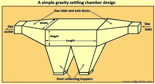
Gbr 1 Desain ruang pengendapan gravitasi sederhana
Dalam menganalisis kinerja ruang pengendapan, fitur utamanya adalah sifat aliran gas melalui perangkat. Dalam hal ini, tiga situasi aliran ideal dasar dapat dibedakan yaitu (i) aliran laminar, (ii) aliran sumbat (kecepatan seragam melintasi penampang) tanpa pencampuran vertikal partikel, dan (iii) aliran sumbat dengan pencampuran vertikal lengkap partikel.
Aliran laminar dicirikan oleh profil kecepatan tipe parabola. Aliran seperti itu hanya direalisasikan untuk bilangan Reynolds di bawahnya untuk transisi ke aliran turbulen. Dalam aliran laminer, waktu yang diperlukan partikel pada ketinggian 'h' di atas lantai ruang untuk mengendap adalah 'h/V' di mana V adalah kecepatan pengendapan partikel. Pencampuran vertikal partikel tidak ada dalam aliran laminar. Efek gerakan Brown biasanya diabaikan relatif terhadap gerakan ke bawah yang stabil karena pengendapan.
Dalam ruang pengendapan aliran laminer, profil kecepatan gas adalah parabola, dan ketika partikel di bawah garis arus pusat mengendap, partikel itu bertemu dengan fluida yang bergerak lebih lambat, dan dengan demikian waktu tinggalnya di dalam ruang meningkat dari apa yang telah terjadi pada garis arus yang lebih tinggi. Di sisi lain, partikel yang awalnya berada di atas garis arus pusat bertemu dengan garis arus yang bergerak lebih cepat saat jatuh hingga melewati garis arus pusat.
Kategori aliran kedua adalah aliran sumbat tanpa pencampuran vertikal partikel. Jenis aliran ini, dalam arti, pendekatan aliran laminar dalam pencampuran vertikal partikel masih diabaikan, tetapi profil kecepatan datar diasumsikan dan partikel semua mengendap pada kecepatan pengendapan mereka. Jenis situasi aliran kedua adalah aliran sumbat tanpa pencampuran partikel secara vertikal. Dalam situasi ini, diasumsikan bahwa partikel terdistribusi secara merata di seluruh pintu masuk ke ruangan. Apakah partikel dikumpulkan ditentukan semata-mata oleh ketinggian 'h' di pintu masuknya di atas permukaan pengumpul. Ketinggian kritis 'h*' dapat didefinisikan sedemikian rupa sehingga semua partikel yang masuk dengan 'h' kurang dari atau sama dengan 'h*' dikumpulkan dan partikel yang 'h' lebih besar dari 'h*' koleksi lepas.
Kategori ketiga, aliran sumbat dengan pencampuran vertikal menyeluruh, adalah aliran turbulen. Dalam ruang pengendapan aliran turbulen, kecepatan gas diasumsikan seragam di seluruh ruang karena pencampuran turbulen. Selain itu, percampuran turbulen di inti ruangan mengalahkan kecenderungan partikel untuk mengendap dan mempertahankan konsentrasi partikel yang seragam secara vertikal di seluruh ruangan. Penghapusan dengan pengendapan dapat diasumsikan terjadi pada lapisan tipis di bagian bawah bilik.
Aliran dalam saluran persegi panjang dapat dianggap turbulen jika bilangan Reynolds lebih besar dari 4.000. Dalam ruang pengendapan aliran laminar, partikel mengendap pada semua ketinggian di atas lantai ruang, kunci analisisnya adalah menghitung waktu tinggal keseluruhan partikel saat jatuh melintasi garis arus. Mekanisme pengumpulan di ruang pengendapan aliran turbulen, meskipun pada akhirnya didasarkan pada pengendapan partikel di bawah gravitasi, agak berbeda dari yang di ruang aliran laminar. Perbedaannya adalah karena aliran turbulen di dalam chamber. Dalam aliran curah di dalam ruangan, pencampuran turbulen cukup kuat sehingga partikel terbebani oleh aliran dan tidak mengendap. Diasumsikan bahwa pencampuran turbulen mempertahankan konsentrasi partikel yang seragam di atas ketinggian ruangan. Sangat dekat lantai ruangan, lapisan tipis dapat diasumsikan ada di mana partikel mengendap jarak pendek ke lantai. Jadi, begitu sebuah partikel, yang tercampur kuat di inti aliran, memasuki lapisan ini, ia mengendap di lantai.
Pemisah siklon
Pemisah siklon adalah perangkat pembersih gas yang memanfaatkan gaya sentrifugal yang diciptakan oleh aliran gas yang berputar untuk memisahkan partikel dari gas. Pemisah siklon aliran balik vertikal tangensial inlet standar ditunjukkan pada Gambar 2. Aliran gas dipaksa untuk mengikuti geometri melengkung siklon sementara inersia partikel dalam aliran menyebabkan mereka bergerak menuju dinding luar, di mana mereka bertabrakan dan saling bertabrakan. dikumpulkan. Sebuah partikel bermassa 'm' bergerak dalam lintasan melingkar berjari-jari 'r' dengan kecepatan tangensial 'vA' dikenai gaya sentrifugal 'm(vA)2/r'. Pada nilai tipikal 'vA' =10 m/s, 'r' =0,5 m, gaya ini 20,4 kali gravitasi pada partikel yang sama. Dengan demikian dapat dilihat bahwa gaya yang ditingkatkan secara substansial pada partikel di atas gaya pengendapan saja dapat dicapai untuk geometri siklon.
Dalam siklon, partikel-partikel dalam aliran gas yang berputar bergerak semakin dekat ke dinding luar saat mereka mengalir melalui perangkat. Seperti yang ditunjukkan pada Gambar 2, aliran gas dapat melakukan beberapa putaran penuh saat mengalir dari satu ujung perangkat ke ujung lainnya. Untuk desain pemisah siklon, laju aliran gas yang diberikan dan jari-jari dalam dan luar, panjang badan siklon adalah untuk memastikan bahwa efisiensi pengumpulan yang diinginkan untuk partikel dengan ukuran tertentu dapat dicapai. Karena panjang badan siklon terkait melalui laju aliran gas dengan jumlah putaran yang dilakukan oleh aliran gas, desain sering kali terdiri dari menghitung jumlah putaran yang diperlukan untuk mencapai efisiensi pengumpulan yang ditentukan.
Ada berbagai desain yang tersedia untuk pemisah siklon yang berbeda dalam cara di mana gerakan berputar diberikan ke aliran gas. Siklon konvensional dapat terdiri dari tiga kategori yaitu (i) siklon aliran balik (inlet tangensial dan inlet aksial), (ii) siklon aliran lurus, dan (iii) kolektor impeller.
Gambar 2 menunjukkan siklon aliran balik konvensional dengan saluran masuk tangensial. Gas kotor masuk di bagian atas siklon dan diberi gerakan berputar karena entri tangensialnya. Partikel dipaksa ke dinding dengan gaya sentrifugal dan kemudian jatuh ke dinding karena gravitasi. Di bagian bawah siklon aliran gas berbalik untuk membentuk inti bagian dalam yang meninggalkan di bagian atas siklon. Dalam siklon saluran masuk aksial aliran balik, gas masuk dimasukkan ke bawah sumbu siklon, dengan gerakan sentrifugal yang diberikan oleh baling-baling permanen di bagian atas.
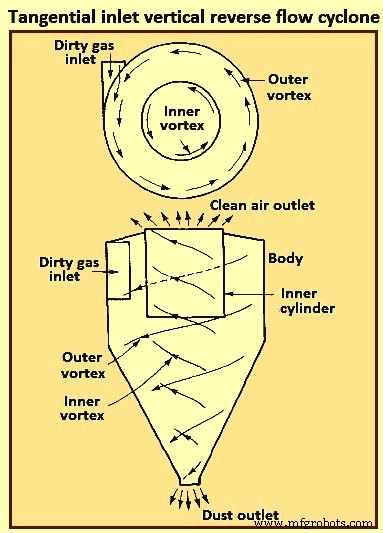
Gbr 2 Siklon aliran balik vertikal saluran masuk tangensial
Dalam siklon aliran lurus, pusaran udara bagian dalam meninggalkan di bagian bawah (bukan membalikkan arah), dengan gerakan sentrifugal awal yang diberikan oleh baling-baling di bagian atas. Jenis ini sering digunakan sebagai pembersih awal untuk menghilangkan partikel besar. Keuntungan utama dari siklon ini adalah penurunan tekanan yang rendah dan laju aliran volumetrik yang tinggi.
Dalam kolektor impeller, gas masuk normal ke impeller berbilah banyak dan tersapu oleh impeller di sekitar kelilingnya sementara partikel dilemparkan ke dalam slot annular di sekitar pinggiran siklon. Keuntungan utama dari siklon ini adalah kekompakannya. Kerugian utama dari siklon adalah kecenderungan penyumbatan dari penumpukan padat di siklon.
Siklon dapat dibuat dari bahan apa saja, logam atau keramik. Mereka mampu menahan suhu tinggi, partikel abrasif, atau atmosfer korosif. Permukaan interior harus halus sehingga partikel yang terkumpul dapat meluncur dengan mudah ke bawah dinding ke hopper. Tidak ada bagian yang bergerak dalam siklon, sehingga pengoperasiannya biasanya sederhana dan relatif bebas perawatan. Biaya modal rendah dan operasi bebas perawatan membuatnya ideal untuk digunakan sebagai pra-pembersih untuk perangkat kontrol akhir yang lebih efisien, seperti ESP. Meskipun siklon secara tradisional dianggap sebagai kolektor dengan efisiensi yang relatif rendah, beberapa siklon yang tersedia saat ini dapat mencapai efisiensi yang lebih tinggi dari 98% untuk partikel yang lebih besar dari 5 mikrometer. Biasanya, siklon secara rutin mencapai efisiensi 90% untuk partikel yang lebih besar dari 15 mikrometer hingga 20 mikrometer.
Gambar 3 menunjukkan partikel masuk tangensial ke bidang horizontal aliran gas berputar di r3 dianggap. Karena gaya sentrifugal 'm(vA)2/r', partikel mengikuti jalan keluar melintasi garis arus. Vektor kecepatannya memiliki komponen tangensial (vA) dan komponen radial (Vr). Ada juga komponen aksial (vZ).
Pemisah siklon aliran laminar tidak memiliki aliran laminar dalam arti ruang pengendapan aliran laminar, melainkan aliran tanpa gesekan di mana garis arus mengikuti kontur siklon seperti yang ditunjukkan pada Gambar 3.
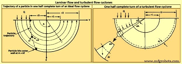
Gbr 3 aliran laminar dan aliran turbulen siklon
Model pemisah siklon aliran turbulen ditunjukkan pada Gambar 3. Karena pencampuran turbulen, konsentrasi partikel diasumsikan seragam di seluruh siklon, dan, seperti dalam kasus ruang pengendapan aliran turbulen, penghilangan terjadi melintasi lapisan tipis di dinding luar.
Efisiensi pengumpulan siklon meningkat dengan meningkatnya (i) ukuran partikel, (ii) kerapatan partikel, (iii) kecepatan gas masuk, (iv) panjang badan siklon, (v) jumlah putaran gas, dan (vi) kehalusan dinding siklon. Di sisi lain, efisiensi siklon menurun dengan meningkatnya (i) diameter siklon, (ii) diameter saluran keluar gas, dan (iii) luas saluran masuk gas. Untuk setiap siklon tertentu, yang rasio dimensinya tetap, efisiensi pengumpulan meningkat seiring dengan penurunan diameter siklon. Desain pemisah siklon mewakili kompromi antara efisiensi pengumpulan, penurunan tekanan, dan ukuran. Higher efficiencies need higher pressure drops (i.e., inlet gas velocities) and larger sizes (i.e. body length). The dimensions required to specify a tangential-entry, reverse-flow cyclone are shown in Fig 4.
Besides collection efficiency the other major consideration in cyclone specification is pressure drop. While higher efficiencies are achieved by forcing the gas through the cyclone at higher velocities, to do so results in an increased pressure drop. Since increased pressure drop needs increased energy input into the gas, there is ultimately an economic trade-off between collection efficiency and operating cost. Cyclone pressure drops normally range from 250 Pa to 4,000 Pa.
Electrostatic precipitator
ESP is one of the most widely used particulate control device. It has wide size ranges. The ESP chamber consists of two electrodes, the discharge and the collecting electrodes. Between the electrodes, the gas contains free electrons, ions, and charged particles. The species contributing to the space charge density are ions, electrons, and charged particles. The gas molecules capture all the free electrons so that only the ions and charged particles contribute space charge density. Actually, ionic current flows in the direction of the electric field consisting of ions charged with the same polarity as the charging electrode and moving to the collecting electrode. The ions migrate to the collecting electrode with a velocity large enough to be unaffected by the turbulent flow in the chamber.
The basic principle of operation of the ESP is that the particles are charged, and then an electric field is imposed on the region through which the particle-laden gas is flowing, exerting an attractive force on the particles and causing them to migrate to the oppositely charged electrode at right angles to the direction of gas flow. ESP differs from mechanical methods of particle separation in that the external force is applied directly to the individual particles rather than indirectly through forces applied to the entire gas stream (e.g. in a cyclone separator). Particles collect on the electrode. If the particles collected are liquid, then the liquid flows down the electrode by gravity and it is removed at the bottom of the device. If the particles are solid, the collected layer on the electrode is removed periodically by rapping the electrode.
Particle charging is achieved by generating ions by means of a corona established surrounding a highly charged electrode like a wire. The electric field is applied between that electrode and the collecting electrode. If the same pair of electrodes serves for particle charging and collecting, the device is called a single-stage ESP (Fig 4). A wire serving as the discharge electrode is suspended down the axis of a tube and held in place by a weight attached at the bottom. The sides of the cylinder form the collecting electrode. The collected particles which form a layer on the collecting electrode are removed to the dust hopper by rapping the collecting electrode. In a two-stage ESP, separate electrode pairs perform the charging and collecting functions.
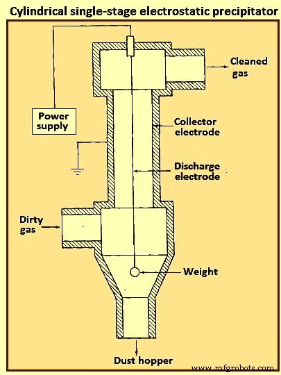
Fig 4 Cylindrical single-stage electrostatic precipitator
Most industrially generated particles are charged during their formation by such means as flame ionization and friction, but normally only to a low or moderate degree. These natural charges are far too low for electrostatic precipitation. The high-voltage DC (direct current) corona is the most effective means for particle charging and is universally used for electrostatic precipitation. The corona is formed between an active high voltage electrode such as a fine wire and a passive ground electrode such as a plate or pipe. The corona surrounding the discharge electrode can lead to the formation of either positive or negative ions which migrate to the collecting electrode. The ions, in migrating from the discharging to the collecting electrode, collide with the particulate matter and charge the particles.
Since the gas molecule ions are many orders of magnitude smaller than even the smallest particles and because of their great number, virtually all particles that flow through the device become charged. The charged particles are then transported to the collecting electrode, to which they are held by the electrostatic attraction. The particles build a thickening layer on the collecting electrode. The charge slowly bleeds from the particles to the electrode. As the layer grows, the charges on the most recently collected particles are to be conducted through the layer of previously collected particles. The resistance of the dust layer is called the dust resistivity.
As the particle layer grows in thickness, the particles closest to the plates lose most of their charge to the electrode. As a result, the electrical attraction between the electrode and these particles is weakened. However, the newly arrived particles on the outside layer have a full charge. Because of the insulating layer of particles, these new particles do not lose their charge immediately and thus serve to hold the entire layer against the electrode. Finally, the layer is removed by rapping, so that the layer breaks up and falls into a collecting hopper. ESPs are normally employed for gas cleaning when the volumetric throughput of gas is high.
The mechanism for particle charging in a ESP is the generation of a supply of ions which attach themselves to the particles. The corona is the mechanism for forming ions. The corona can be either positive or negative. A gas normally has a few free electrons and an equal number of positive ions, a situation which is exploited in generating a corona. When a gas is placed between two electrodes, small amount of current results as the free electrons migrate to the positive electrode and the positive ions migrate to the negative electrode.
In the positive corona discharge electrode, the wire in the cylindrical ESP (Fig 4) is at a positive potential. The few free electrons normally present in the gas migrate toward the wire. As the electrons approach the wire, the electrons’ energy is increased because of an increase in the attractive force. These free electrons collide with gas molecules, the collision leading in some cases to the ejection of an electron from the molecule, producing two free electrons and a positive ion. The two free electrons continue toward the positive electrode, gaining energy, until they collide with two more gas molecules, producing four free electrons and two positive ions. This process is referred to as an electron avalanche.
The positive ions formed migrate to the negative electrode. It is these positive ions which migrate across the entire device to the negative electrode that collide with and attach to the particles in the gas. The region immediately surrounding the wire in which the electron avalanche is established is the corona. Thus, with a positive corona the particles become positively charged. The term ‘corona’ arises from the fact that the electron avalanche is frequently accompanied by the production of light. In the negative corona the discharge electrode is maintained at a negative potential.
The electron avalanche begins at the outer surface of the wire and proceeds radially outward. Close to the wire the electrons are sufficiently energetic to form positive ions upon collision with gas molecules, thus initiating the electron avalanche. The positive ions formed migrate the short distance to the wire. As the electrons migrate outward into a region of lower electric field strength, they are slowed down by collisions with gas molecules. These electrons eventually have lower energy than those which are accelerated toward the positive electrode in the positive corona. These relatively low energy electrons, rather than ejecting an electron from the gas molecule upon collision, are absorbed by the gas molecules to produce negative ions. The formation of negative ions, which begins to occur at the outer edge of the corona, essentially absorbs all the free electrons produced in the electron avalanche at the wire surface. These negative ions then migrate to the positive electrode, in the course of which attaching to gas molecules and forming negative ions.
For a negative corona to be effective, it is necessary that the gas molecules can absorb free electrons to form negative ions. Sulphur dioxide is one of the best electron absorbing gases of those present in flue gases. Oxygen, CO2, and H2O are also effective electron absorbers. The negative corona is normally more stable than the positive corona, so it is preferred in most industrial applications. A by-product of the negative corona is the production of ozone (O3). The positive corona does not need an electron-absorbing gas.
As the ESP is operated, a layer of the collected material builds up on the collecting electrode. Particle deposits on the precipitator collection surface are to possess at least a small degree of electrical conductivity in order to conduct the ion currents from the corona to ground. The minimum conductivity required is around 10 to the power -10 per ohm-centimeter (resistivity of 10 to the power 10 ohm-centimeter). This conductivity is small compared to that of ordinary metals but is much greater than that of good insulators such as silica and most plastics. The resistivity of a material is determined by establishing a current flow through a slab of known thickness of the material.
As long as the resistivity of the collected dust layer is less than about 10 to the power 10 ohm-centimeter, the layer surrender its charge to the electrode. At the room temperature, a typical dust has a resistivity of around 10 to the power 8 ohm-centimeter. This is because of a layer of water on the surface of the particles. As the temperature is increased beyond 100 deg C, the water is evaporated and the resistivity increases to a value characteristic of the collected solids. When the resistivity of the layer exceeds around 10 to the power 10 ohm-centimeter, the potential across the layer increases so that the voltage which can be maintained across the ESP decreases and the collection efficiency decreases. The electrical resistivity of collected particulate matter depends on its chemical composition, the constituents of the gas, and the temperature.
Particle charging in ESP occurs in the gas space between the electrodes where the gas ions generated by the corona bombard and become attached to the particles. The gas ions can reach concentrations as high as 10 to the power 15 ions per cubic meter. The level of charge attained by a particle depends on the gas ion concentration, the electric field strength, the conductive properties of the particle, and the particle size. A 1 micrometer particle typically acquires the order of 300 electron charges, whereas a 10 micrometer particle can attain 30,000 electron charges. Predicting the level of charge acquired by a particle is necessary in order to predict the particle’s migration velocity, on the basis of which the collection efficiency can be calculated for a given set of operating conditions.
There are actually two mechanisms by which particles become charged in an ESP. In the first mechanism particle charging occurs when ions which are migrating toward the collecting electrode encounter particles to which they become attached. In migrating between the electrodes the ions follow the electric flux lines, which are curves everywhere tangent to the electric field vector. When the particle first enters the device and is uncharged, the electric flux lines deflect toward the particle, resulting in the capture of even a larger number of ions than are captured if the ions have followed their normal path between the electrodes. As the particle becomes charged, ions begin to be repelled by the particle, reducing the rate of charging. Eventually, the particle acquires a saturation charge and charging ceases. This mechanism is called ion bombardment or field charging.
The second mode of particle charging is diffusion charging, in which the particle acquires a charge by virtue of the random thermal motion of ions and their collision with and adherence to the particles. Diffusion charging occurs as the ions in their random thermal motion collide with a particle and surrender their charge to it. In that sense the mechanism of diffusion charging is identical to that of the diffusion of uncharged vapour molecules to the surface of a particle. However, because both the particle and the ions are charged, the random thermal motion of the ions in the vicinity of a particle is influenced by an electrostatic force. This force gives rise to a tendency of the ions to migrate away from the particle as the particle charge increases. The overall flux of ions to a particle hence is both the random diffusive motion and the electrical migration.
The theories of both field and diffusion charging, in their full generality, are quite complex and have received a great deal of attention. Strictly speaking, field and diffusion charging occur simultaneously once a particle enters an ESP, and hence to predict the overall charge acquired by a particle, one is to consider the two mechanisms together. However, since the diffusion charging is predominant for particles smaller than around 1 micrometer in diameter and field charging is predominant for particles larger than around 1 micrometer, the two mechanisms frequently are treated in ESP design as if they occur independently. In doing so, one estimates the total charge on a particle as the sum of the charges resulting from each of the two separate mechanisms.
Filtration of particles from gas streams
A major class of particulate air pollution control devices relies on the filtration of particles from gas streams. A variety of filter media is employed, including fibrous beds, packed beds, and fabrics. Fibrous beds used to collect airborne particles are typically quite sparsely packed, usually only around 10 % of the bed volume being fibers. Packed bed filters consist of solid packing normally in a tube and tend to have higher packing densities than do fibrous filters. Both fibrous and packed beds are widely used in the ventilation systems. Fabric filters are frequently used to remove solid particles from industrial gases, whereby the dusty gas flows through fabric bags and the particles accumulate on the cloth.
The physical mechanisms by which the filtration is accomplished vary depending on the mode of filtration. Conventional sparsely packed fibrous beds can be viewed as assemblages of cylinders. In such a filter, the characteristic spacing between fibers is much larger than the size of the particles being collected. Thus the mechanism of collection is not simply sieving, in which the particles are trapped in the void spaces between fibers. Rather, the removal of particles occurs by the transport of particles from the gas to the surface of a single collecting element. Because the filtration mechanisms in a fibrous bed can be analyzed in terms of a single collector, it is possible to describe them in considerable theoretical detail.
Packed-bed filters are sometimes viewed as assemblages of interacting, but essentially separate, spherical collectors, although the close proximity of individual packing elements casts doubt as to the validity of this approach. Because of the relatively closer packing in packed-bed filters, and the resulting difficulty of describing the particle collection process in clean theoretical terms, predicting collection in such systems is more empirically based than for fibrous filters. Fabric filter efficiencies must be predicted strictly empirically since the accumulated particle layer actually does the collecting.
A fibrous filter bed is viewed as a loosely packed assemblage of single cylinders. Even though the fibers are oriented in all directions in the bed, from a theoretical point of view the bed is treated as if every fiber is normal to the gas flow through the bed. The solid fraction of the filter is normally of the order of only 10 %. In addition, each fiber acts more or less independently as a collector. Thus, to compute the particle removal by a filter bed, one basically needs to determine the number of fibers per unit volume of the bed and then multiply that quantity by the efficiency of a single fiber.
The basis of predicting the collection efficiency of a filter bed is the collection efficiency of a single filter element in the bed. The filter element is taken as an isolated cylinder normal to the gas flow. Three distinct mechanisms as given below can be identified whereby particles in the gas reach the surface of the cylinder.
As per the first mechanism, the particles in a gas undergo Brownian diffusion which brings some particles in contact with the cylinder due to their random motion as they are carried past the cylinder by the flow. A concentration gradient is established after the collection of a few particles and acts as a driving force to increase the rate of deposition over that which occurs in the absence of Brownian motion. Because the Brownian diffusivity of particles increases as particle size decreases, it is normally expected that this removal mechanism is the most important for very small particles. When analyzing collection by Brownian diffusion, the particles are treated as diffusing mass-less points.
As per the second mechanism, interception takes place when a particle, following the streamlines of flow around a cylinder, is of a size sufficiently large that its surface and that of the cylinder come into contact. Thus, if the streamline on which the particle centre lies is within a distance Dp /2 of the cylinder, interception occurs. Here Dp is the particle diameter.
As per the third mechanism, inertial impaction occurs when a particle is unable to follow the rapidly curving streamlines around an obstacle and, because of its inertia, continues to move toward the obstacle along a path of less curvature than the flow streamlines. Thus, collision occurs because of the particle’s momentum. It is to be noted that the mechanism of inertial impaction is based on the premise that the particle has mass but no size, whereas interception is based on the premise that the particle has size but no mass.
Collection can also result from electrostatic attraction when either particles or fiber or both possess a static charge. These electrostatic forces can be either direct, when both particle and fiber are charged, or induced, when only one of them is charged. Such charges are normally not present unless deliberately introduced during the production of the fiber.
The size ranges in which the various mechanisms of collection are important are (i) Inertial impaction – greater than 1 micrometer, (ii) Interception – greater than 1 micrometer, (iii) diffusion – less than 0.5 micrometer, and (iv) electrostatic attraction – 0.01 micrometer to 5 micrometer. It is normal to analyze the mechanisms of collection separately and then combine the individual efficiencies to give the overall collection efficiency for the cylinder or other obstacle.
Most developments of particle collection assume, for lack of better information, that particles transported to the surface of a fiber are retained by the fiber. Experiments have shown, however, that for a variety of substances and filter media, the fraction of particles striking the collector surface which adhere is generally less than unity and can in some cases be as low as 0.5.
Industrial fabric filtration is normally accomplished in a so-called bag- house, in which the particle-laden gases are forced through filter bags. Particles are normally removed from the bags by gravity. Fig 5 shows three bag-house designs, in which cleaning is accomplished by vibration (Fig 5a), air jet [Fig 5b), or traveling ring [Fig 5c).
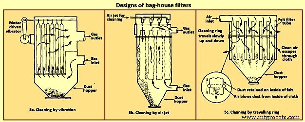
Fig 5 Designs of bag house filters
The fabric filtration process consists of three phases. First, particles collect on individual fibers by the above described mechanisms. Then an intermediate stage exists during which particles accumulate on previously collected particles, bridging the fibers. Finally, the collected particles form a cake in the form of a dust layer which acts as a packed bed filter for the incoming particles. As the dust layer accumulates, the pressure drop across the filter increases, and periodically the dust layer is to be dislodged into the hopper at the bottom to ‘regenerate’ the fabric bag. High efficiencies are attainable with fabric filters, particularly in treating combustion gases from the technological processes. To the extent that effective operation of an ESP depends on the presence of SO2 in the gas as an ionizable species, fabric filters can operate with no loss of efficiency with low-sulphur level.
Fabric filters consist of semi-permeable woven or felted materials which constitute a support for the particles to be removed. A brand-new woven filter cloth has fibers roughly 100 micrometers to 150 micrometers in diameter with open spaces between the fibers of 50 micrometers to 75 micrometers. Initially, the collection efficiency of such a cloth is low because most of the particles pass directly through the fabric. However, deposited particles quickly accumulate, and it is the deposited particle layer that enables the high-efficiency removal once a uniform surface layer has been established.
Although fiber mat filters are similar in some respects to fabric filters, they do not depend on the layer of accumulated particles for high efficiency. Fiber mat filters generally are not cleaned but are discarded. They are ordinarily used when particle concentrations are low, so that reasonable service life can be achieved before discarding.
In a fabric filter the particle layer performs the removal task. As the layer of collected particles grows in thickness, there is an increase in the pressure drop across the particle layer and the underlying fabric. The two major considerations in the design of a fabric filter assembly are the collection efficiency and the pressure drop as a function of time of operation (since the last cleaning). The collection efficiency depends on the local gas velocity and the particle loading on the fabric.
Fabric filters offer the several advantages such as (i) they can achieve very high collection efficiencies even for very small particles, (ii) they can be used for a wide variety of particles, (iii) they can operate over a wide range of volumetric flow rates, and (iv) they need only moderate pressure drops. The limitations of fabric filters are namely (i) operation is to be carried out at temperatures lower than that at which the fabric is destroyed, or its life is shortened to an uneconomical degree, (ii) gas or particle constituents which attack the fabric or prevent proper cleaning, such as sticky particles difficult to dislodge, are to be avoided, and (iii) bag houses need large floor areas. The advantages of fabric filter bag houses clearly outweigh their limitations.
Wet collectors
Wet collectors, or scrubbers, employ water washing to remove particles directly from a gas stream. Scrubbers can be grouped broadly into two main classes namely (i) those in which an array of liquid drops (sprays) form the collecting medium, and (ii) those in which wetted surfaces of various types constitute the collecting medium. The first class includes spray towers and venturi scrubbers, while the second includes plate and packed towers.
Scrubbing is a very effective means of removing small particles from a gas. Removal of particles results from collisions between particles and water drops. In the humid environment of a scrubber, small, dry particles also grow in size by condensation of water and thereby become easier to remove. Re-entrainment of particles is avoided since the particles become trapped in droplets or in a liquid layer. A scrubber also provides the possibility of simultaneously removing soluble gaseous pollutants. The particle-laden scrubbing liquid is to be disposed of, a problem not encountered in dry methods of gas cleaning.
A spray scrubber is a device in which a liquid stream is broken into drops, approximately in the range 0.1 mm to 1 mm in diameter, and introduced into the particle laden gas stream. The array of moving drops becomes a set of targets for collection of the particles in the gas stream. Collection efficiency is computed by considering the efficiency of a single spherical collector and then summing over the number of drops per unit volume of gas flow. The relative motion between the drops and particles is an important factor in the collection efficiency since capture occurs by impaction and direct interception. Diffusion is also important for smaller particles.
There are two general types of spray scrubbers. The first class comprises those having a preformed spray where drops are formed by atomizer nozzles and sprayed into the gas stream. These include (i) counter-current gravity tower, where drops settle vertically against the rising gas stream, (ii) cross-current tower, where drops settle through a horizontal gas stream, and (iii) co-current tower, where spray is horizontal into a horizontal gas stream.
The second class comprises those in which the liquid is atomized by the gas stream itself. Liquid is introduced more or less in bulk into a high-velocity gas flow which shatters the liquid into drops. Devices in this class are called venturi scrubbers since the high velocity gas flow is achieved in a venturi (a contraction). Fig 6 shows four types of wet collection equipment.
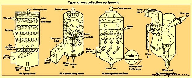
Fig 6 Types of wet collection equipment
The simplest type of wet collector is a spray tower into which water is introduced by means of spray nozzles (Fig 6a). Gas flow in a spray chamber is counter-current to the liquid, the configuration leading to maximum efficiency. Collection efficiency can be improved over the simple spray chamber with the use of a cyclonic spray tower, as shown in Fig 6b. The liquid spray is directed outward from nozzles in a central pipe. An unsprayed section above the nozzles is provided so that the liquid drops with the collected particles have time to reach the walls of the chamber before exit of the gas. An impingement plate scrubber, as shown in Fig 6c, consists of a tower containing layers of baffled plates with holes (5,000 to 50,000 per square meter) through which the gas must rise and over which the water must fall. Highest collection efficiencies of wet collectors are obtained in a venturi scrubber, shown in Fig 6d, in which water is introduced at right angles to a high-velocity gas flow in a venturi tube, resulting in the formation of very small water droplets by the flow and high relative velocities of water and particles. The high gas velocity is responsible for the breakup of the liquid. Aside from the small droplet size and high impingement velocities, collection is enhanced through particle growth by condensation. Different types of particle scrubbing devices are described below.
Plate scrubber – It is a vertical tower containing one or more horizontal plates (trays). Gas enters the bottom of the tower and must pass through perforations in each plate as the gas flows counter-current to the descending water stream. Plate scrubbers are normally named for the type of plates they contain (e.g. sieve plate tower). Collection efficiency increases as the diameter of the perforations decreases. A cut diameter, that collects with 50 % efficiency, of around 1 micrometer aerodynamic diameter can be achieved with 3.2 mm diameter holes in a sieve plate.
Packed-bed scrubber – It operates similarly to packed-bed gas absorber. Collection efficiency increases as packing size decreases. A cut diameter of 1.5 micrometers aerodynamic diameter can be attained in columns packed with 2.5 cm elements.
Spray scrubber – In this scrubber, particles are collected by liquid drops which have been atomized by spray nozzles. Horizontal and vertical gas flows are used, as well as spray introduced co-current, counter-current, or cross-flow to the gas. Collection efficiency depends on droplet size, gas velocity, liquid / gas ratio, and droplet trajectories. For droplets falling at their terminal velocity, the optimum droplet diameter for fine-particle collection lays in the range 100 micrometers to 500 micrometers. Gravitational settling scrubbers can achieve cut diameters of around 2 micrometers. The liquid / gas ratio is in the range 0.001 cum to 0.01 cum per cum of gas treated.
Venturi scrubber – A moving gas stream is used to atomize liquids into droplets. High gas velocities (60 m/sec to 120 m/s) lead to high relative velocities between gas and particles and promote collection.
Cyclone scrubber – Drops can be introduced into the gas stream of a cyclone to collect particles. The spray can be directed outward from a central manifold or inward from the collector wall.
Baffle scrubber – In this scrubber, there are changes in gas flow velocity and direction induced by solid surfaces.
Impingement-entrainment scrubber – The gas is forced to impinge on a liquid surface to reach a gas exit. Some of the liquid atomizes into drops which are entrained by the gas. The gas exit is designed so as to minimize the loss of entrained droplets.
Fluidized-bed scrubber – A zone of fluidized packing is provided where gas and liquid can mix intimately. Gas passes upward through the packing, while liquid is sprayed up from the bottom and / or flows down over the top of the fluidized layer of packing.
The collection efficiency of wet collectors can be related to the total energy loss in the equipment. The higher is the scrubber power per unit volume of gas treated, the better is the collection efficiency. Almost all the energy is introduced in the gas, and thus the energy loss can be measured by the pressure drop of gas through the unit. The major advantage of wet collectors is the wide variety of types, allowing the selection of a unit suitable to the particular removal problem. As regards disadvantages, high pressure drops (and hence energy requirements) are to be maintained, and the handling and disposal of large volumes of scrubbing liquid are to be undertaken.
In case of spray scrubbing, the conceptually simplest of the devices is a gravity spray chamber. Water droplets are introduced at the top of an empty chamber through atomizing nozzles and fall freely at their terminal settling velocities counter-currently through the rising gas stream. The particle-containing liquid collects in a pool at the bottom and is to be pumped out for treatment to remove the solids, and the cleaned liquid is normally recycled to the tower. The overall efficiency of a spray tower increases as the collection efficiency of a single drop increases, as the length of the chamber increases, and as the ratio of the volumetric flow rate of water to that of gas increases. It increases as the diameter of the drops decreases.
Venturi scrubbers are used when high collection efficiencies are needed and when most of the particles are smaller than 2 micrometers in diameter. There are a number of examples, in fact, where a venturi scrubber is the only practical device for a gas-cleaning application. If the particles to be removed are sticky, flammable, or highly corrosive, for example, ESPs and fabric filters cannot be used. Venturi scrubbers are also the only high-efficiency particulate collectors which can simultaneously remove gaseous species from the effluent stream.
The distinguishing feature of a venturi scrubber is a constricted cross section or throat through which the gas is forced to flow at high velocity. A typical venturi scrubber configuration is shown in Fig 7. The configuration includes a converging conical section where the gas is accelerated to throat velocity, a cylindrical throat, and a conical expander where the gas is slowed down. Liquid can be introduced either through tangential holes in the inlet cone or in the throat itself. In the former case, the liquid enters the venturi as a film on the wall and flows down the wall to the throat, where it is atomized by the high-velocity gas stream. In the latter, the liquid is injected perpendicular to the gas flow in the throat, atomized, and then accelerated. Gas velocities in the range 60 m/sec to 120 m/sec are achieved, and the high relative velocity between the particle laden gas flow and the droplets promotes collection. The collection process is essentially complete by the end of the throat. Because they operate at much higher velocities than ESPs precipitators or bag houses, venturi scrubbers are physically smaller and can be economically made of corrosion-resistant materials. Venturis have the simplest configuration of the scrubbers and are the smallest in size. Fig 7 shows the comparison of the efficiency of venturi scrubber with the efficiencies of other gas cleaning devices.
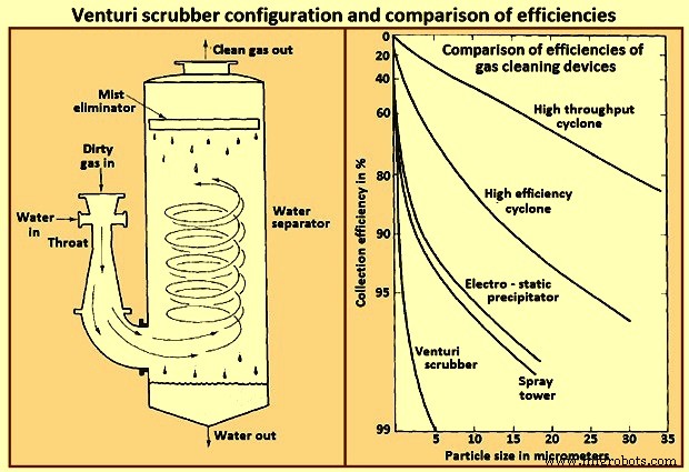
Fig 7 Venturi scrubber configuration and comparison of efficiencies
A typical range of liquid to gas flow rate ratios for a venturi scrubber is 0.001 cum to 0.003 cum of liquid per cum of gas. At the higher liquid / gas ratios, the gas velocity at a given pressure drop is reduced, and at lower ratios, the velocity is increased. For gas flow rates exceeding about 1,000 cum / minute venturi scrubbers are normally constructed in a rectangular configuration in order to maintain an equal distribution of liquid over the throat area.


