Jenis Pencetakan 3D:7 Kategori Utama Teknologi Pencetakan 3D
Ketika kebanyakan orang mendengar “pencetakan 3D”, mereka membayangkan mesin desktop kecil yang membuat komponen plastik. Namun masih banyak hal lain yang terjadi di balik layar. Apa yang kami sebut pencetakan 3D sebenarnya adalah sekelompok teknologi berbeda yang membangun objek lapis demi lapis dari desain digital.
Berbeda dengan manufaktur tradisional, yang bahannya diukir dari balok padat, printer 3D hanya menambahkan bahan sesuai kebutuhan.
Menurut standar ISO/ASTM 52900-15, pencetakan 3D dibagi menjadi tujuh kategori, fotopolimerisasi tong, pengaliran material, pengaliran pengikat, fusi lapisan bubuk, ekstrusi material, deposisi energi terarah, dan laminasi lembaran. Masing-masing menggunakan pendekatan yang berbeda, dan masing-masing memiliki kelebihannya sendiri bergantung pada bahan yang Anda gunakan, anggaran Anda, dan seberapa rumit bagian Anda.
Beberapa metode pencetakan 3D tercanggih saat ini sudah ada sejak tahun 1980-an. Stereolitografi (SLA) dipatenkan pada tahun 1986, dan sejak itu, kami telah melihat terobosan besar, seperti FDM, SLS, dan MJF yang masing-masing dirancang untuk tujuan berbeda:kecepatan, detail, jangkauan material, atau efisiensi biaya.
Anda sekarang dapat menemukan mesin desktop dengan harga di bawah $200 dan sistem kelas industri yang berharga lebih dari $1 juta. Mulai dari PLA dan ABS hingga bubuk logam, keramik, dan resin fotopolimer, industri pencetakan 3D telah berkembang menjadi alat yang serius baik bagi penghobi maupun insinyur manufaktur.
Dalam artikel ini, kami akan menguraikan setiap jenis pencetakan 3D utama, mempelajari cara kerjanya, dan membantu Anda mengetahui mana yang paling sesuai dengan kebutuhan Anda, baik Anda baru memulai atau meningkatkan produksi.
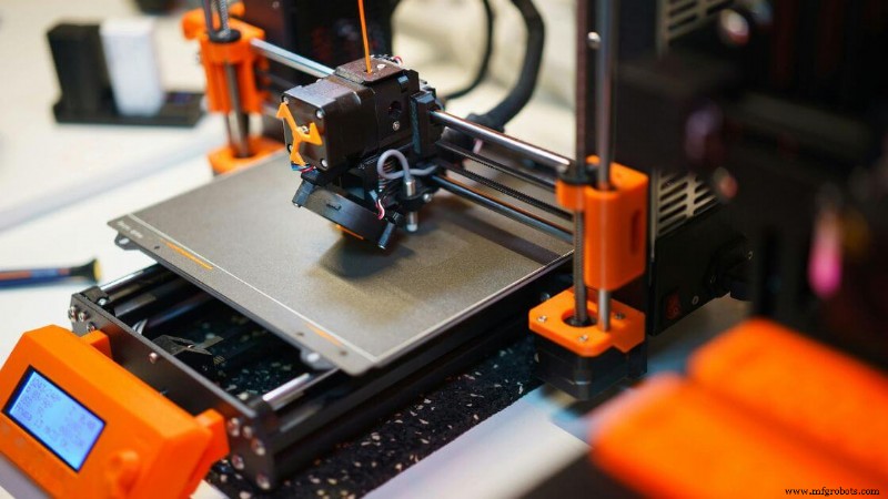
Ekstrusi Material
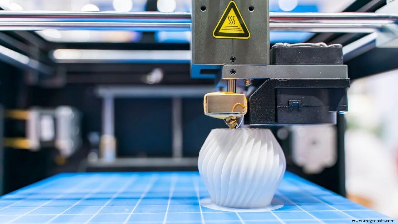 Ekstrusi material mengacu pada sekelompok proses pencetakan 3D di mana material bangunan didorong melalui nosel dan diletakkan lapis demi lapis untuk membentuk bagian tiga dimensi.
Bahan tersebut—biasanya termoplastik—dipanaskan hingga semi-cair, kemudian diekstrusi dalam jalur terkontrol yang dipandu oleh file desain berbantuan komputer. Setiap lapisan menyatu dengan lapisan sebelumnya saat mendingin, membentuk struktur padat.
Ini adalah salah satu jenis metode pencetakan 3D yang paling umum dan mudah diakses. Anda sering melihatnya di printer 3D desktop yang menggunakan spool filamen, namun kategori ini juga mencakup mesin berkapasitas tinggi yang mengeluarkan pelet, beton, atau pasta.
Baik Anda memproduksi komponen kecil atau prototipe skala besar, ekstrusi material menawarkan fleksibilitas yang signifikan dalam desain dan volume pembuatan.
Kisaran materi pencetakan 3D yang didukung sangat luas. Termoplastik standar seperti PLA, ABS, dan PETG merupakan bahan yang umum digunakan, sementara bahan termoplastik yang lebih canggih dapat menangani komposit serat karbon, polimer tahan suhu, atau filamen berisi logam.
Beberapa mesin bahkan digunakan dalam konstruksi atau pemodelan makanan.
Akurasi dimensi biasanya turun sekitar ±0,5 mm, meskipun hal ini bervariasi tergantung peralatan, material, dan pengendalian lingkungan. Objek dengan overhang sering kali memerlukan struktur pendukung untuk mencegah keruntuhan selama pencetakan. Pasca-pemrosesan mungkin diperlukan untuk menyempurnakan permukaan akhir dan menghilangkan penyangga.
Ekstrusi material tetap menjadi pilihan utama untuk pembuatan prototipe karena efisiensi biayanya, terutama jika dibandingkan dengan teknologi yang lebih kompleks seperti sintering laser selektif atau stereolitografi. Hal ini juga berfungsi sebagai dasar untuk pemodelan pengendapan leburan, sebuah implementasi yang banyak digunakan dalam kategori ini.
Fused Deposition Modeling (FDM) atau Fused Filament Fabrication (FFF)
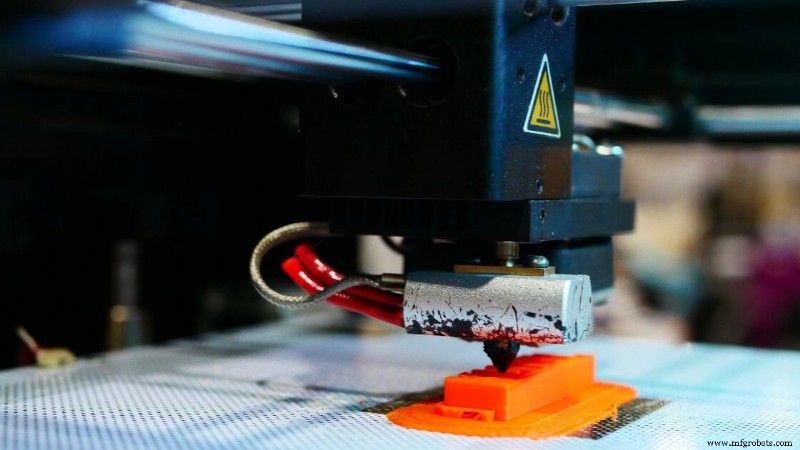
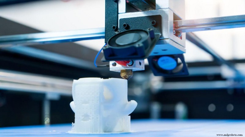
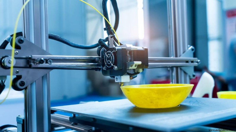
Pemodelan deposisi leburan, juga dikenal sebagai fabrikasi filamen leburan, adalah jenis ekstrusi material di mana filamen termoplastik dimasukkan ke dalam kepala cetak yang dipanaskan. Bahan tersebut meleleh dan dikeluarkan melalui nosel, membentuk setiap lapisan objek 3D saat mendingin dan mengeras di pelat pembuatan.
Anda biasanya akan bekerja dengan bahan seperti PLA, ABS, PETG, dan TPU. Pilihan yang lebih canggih mencakup polikarbonat, ULTEM, dan filamen yang diisi dengan serat karbon atau bubuk logam. Filamen ini dapat menawarkan sifat mekanik yang berbeda tergantung pada kebutuhan fungsional komponen Anda.
Proses ini ideal untuk aplikasi seperti pembuatan prototipe cepat, model pendidikan, pengujian produk konsumen, dan alat bantu manufaktur seperti jig atau perlengkapan.
Pencetakan 3D FDM juga umum dalam alur kerja pengembangan produk yang memerlukan evaluasi geometri komponen atau kesesuaian perakitan sebelum produksi massal.
Akurasi tipikal berkisar sekitar ±0,5 mm, dan resolusi lapisan biasanya berkisar antara 50 hingga 300 mikron. Kecepatan pencetakan bervariasi tergantung pada bahan dan kompleksitas komponen, namun kecepatan standar berkisar antara 40 dan 100 mm/s.
Kelebihan:
- Biaya rendah:Printer dan filamen tingkat pemula tersedia secara luas dengan harga terjangkau.
- Keragaman bahan:Berbagai pilihan plastik dengan berbagai kekuatan, warna, dan hasil akhir.
- Kemudahan penggunaan:Alur kerja perangkat lunak yang sederhana membuatnya mudah didekati oleh pemula dan profesional.
- Skalabilitas:Tersedia mulai dari mesin desktop hingga sistem skala industri dengan volume build yang besar.
Kekurangan:
- Garis lapisan yang terlihat:Bagian sering kali menunjukkan tonjolan di antara lapisan kecuali jika pasca-pemrosesan diterapkan.
- Ikatan antar lapisan lebih lemah:Sifat mekanik mungkin tidak konsisten tergantung pada orientasi bagian.
- Persyaratan pendukung:Overhang dan jembatan mungkin memerlukan material tambahan yang harus dibongkar nanti.
- Presisi lebih rendah:Dibandingkan dengan pencetakan 3D resin atau fusi lapisan bubuk, FDM sulit menangani detail halus.
Pencetakan Bio 3D
 Bioprinting 3D adalah bentuk ekstrusi material khusus yang menggunakan bio-tinta—biasanya terbuat dari sel hidup yang tersuspensi dalam hidrogel—untuk membuat struktur mirip jaringan lapis demi lapis.
Berbeda dengan metode pencetakan 3D tradisional yang mengandalkan termoplastik atau bubuk logam, proses ini memprioritaskan kelangsungan hidup sel dan kompatibilitas biomaterial.
Ekstrusi harus tepat dan cukup lembut untuk menghindari kerusakan komponen hidup, sekaligus membentuk geometri biologis yang fungsional.
Bahan yang akan Anda temukan dalam proses ini mencakup polimer yang dapat terbiodegradasi seperti alginat, kolagen, gelatin, dan fibrin.
Ini berfungsi sebagai perancah untuk mendukung pertumbuhan dan susunan sel. Karena strukturnya harus meniru jaringan asli, bahan ini dipilih karena kompatibilitas, fleksibilitas, dan kemampuannya mendukung vaskularisasi.
Aplikasi berkembang pesat. Anda akan melihat bioprinting 3D digunakan dalam penelitian untuk perangkat organ-on-a-chip, perancah jaringan, model pengobatan regeneratif, dan bahkan biofabrikasi kulit atau tulang rawan tahap awal. Ini bukan sekadar model konsep—ini adalah langkah praktis menuju solusi implan di masa depan.
Akurasi dimensi dapat mencapai antara 100–200 mikron atau lebih, bergantung pada kalibrasi printer dan kekentalan bio-tinta. Namun, performanya bervariasi bergantung pada faktor lingkungan seperti kelembapan, kontrol printhead, dan sterilitas.
Kecepatan pencetakan bergantung pada kepadatan sel, ukuran nosel, dan laju aliran hidrogel. Biasanya, hasil cetakan lebih lambat dibandingkan ekstrusi polimer karena menjaga kesehatan sel lebih penting daripada kecepatan.
Kelebihan:
- Potensi rekayasa jaringan:Menawarkan jalan menuju organ fungsional dan terapi regeneratif.
- Kemampuan untuk disesuaikan:Struktur yang disesuaikan untuk pengujian obat atau implan khusus pasien.
- Kontrol lapis demi lapis:Memungkinkan penempatan spasial berbagai jenis sel.
Kekurangan:
- Kompleksitas tinggi:Membutuhkan kontrol ketat terhadap suhu, sterilitas, dan konsistensi bio-tinta.
- Ketahanan yang terbatas:Konstruksi cetakan sering kali memerlukan pembiakan atau pengondisian segera.
- Rintangan peraturan:Penggunaan klinis memerlukan pengujian ekstensif dan langkah-langkah kepatuhan.
Pencetakan 3D Konstruksi
Pencetakan 3D konstruksi adalah metode manufaktur aditif berskala besar yang menggunakan sistem ekstrusi otomatis, biasanya lengan robot atau nozel yang dipasang di gantri untuk menyimpan material tingkat konstruksi, seperti beton, dalam formasi berlapis.
Tidak seperti metode tradisional, metode ini dibuat langsung dari model digital menggunakan teknologi pencetakan 3D, sehingga dinding, cangkang struktural, atau bahkan seluruh bangunan dapat diproduksi lapis demi lapis tanpa cetakan atau bekisting standar.
Anda biasanya akan melihat material seperti campuran semen, beton cepat mengeras, senyawa geopolimer, dan mortar khusus yang digunakan dalam sistem ini.
Pemilihan bahan dasar harus memenuhi persyaratan kemampuan mengalir dan pengawetan yang ketat, memastikan setiap lapisan bagian baru menyatu dengan baik dengan lapisan sebelumnya sekaligus menjaga integritas struktural.
Pendekatan ini telah mendapatkan daya tarik global dalam proyek-proyek yang bertujuan untuk membangun konstruksi yang berkelanjutan, cepat, dan berbiaya rendah. Dari perumahan bagi masyarakat berpendapatan rendah hingga tempat penampungan darurat dan arsitektur artistik, cakupan penerapannya terus bertambah.
Meskipun teknologi ini masih berkembang, Anda akan menemukan beberapa contoh nyata di mana printer 3D membuat seluruh rumah atau bagian struktural utama hanya dalam hitungan hari—menghemat waktu berminggu-minggu dibandingkan jadwal konstruksi tradisional.
Akurasi biasanya berkisar antara ±5 mm dan ±10 mm tergantung pada ukuran platform pembuatan printer, presisi nozel, dan faktor lingkungan. Kecepatan mencetak dapat bervariasi namun seringkali lebih cepat dibandingkan pekerjaan manual untuk bentuk lurus atau berulang. Resolusi lapisan cenderung kasar, berkisar antara 10 mm dan 30 mm namun dapat ditingkatkan menggunakan teknik finishing.
Kelebihan:
- Mengurangi kebutuhan tenaga kerja, terutama dalam tugas yang berulang
- Mempercepat waktu pembangunan secara signifikan untuk geometri tertentu
- Meminimalkan limbah material selama pemodelan deposisi
- Memungkinkan bentuk arsitektur organik baru yang tidak dapat dilakukan dengan metode tradisional
Kekurangan:
- Membutuhkan peralatan besar, membatasi mobilitas, dan kemudahan penyiapan
- Bahan harus dirancang secara presisi agar mengalir dan cepat mengeras
- Kepatuhan terhadap kode etik dan standar inspeksi masih terus berkembang
- Permukaan akhir dan geometri bagian mungkin memerlukan penyempurnaan manual setelah pencetakan
Fotopolimerisasi PPN
Fotopolimerisasi tong adalah proses pencetakan 3D yang menggunakan cahaya untuk secara selektif mengolah lapisan resin cair menjadi bagian padat. Anda memulai dengan tong berisi resin fotopolimer, biasanya berbahan dasar akrilik yang bereaksi terhadap panjang gelombang cahaya tertentu.
Laser, proyektor cahaya digital, atau layar LCD memandu proses pengawetan ini dengan presisi tinggi. Saat setiap lapisan fotopolimer mengeras, platform pembangunan secara bertahap naik atau turun untuk memungkinkan terbentuknya lapisan berikutnya. Urutan ini berulang hingga keseluruhan objek selesai.
Yang membedakan metode ini adalah kemampuannya menghasilkan detail yang sangat halus dan permukaan akhir yang sangat halus. Oleh karena itu, produk ini lebih disukai untuk aplikasi yang mengutamakan presisi—seperti cetakan gigi, perhiasan rumit, dan komponen medis mini.
Akurasi dimensi dapat berada dalam kisaran ±0,1 mm atau bahkan lebih baik pada mesin yang disetel dengan baik, dan geometri komponen tetap konsisten karena paparan cahaya yang terkontrol dan perilaku aliran resin.
Anda juga akan menemukan proses ini dalam berbagai format—SLA, DLP, dan LCD—masing-masing menggunakan sumber cahaya yang sedikit berbeda namun beroperasi berdasarkan prinsip umum yang sama:fotopolimerisasi.
Resin yang digunakan dalam mesin ini hadir dalam berbagai formulasi—beberapa dioptimalkan untuk ketangguhan, yang lain untuk fleksibilitas, kejernihan, atau ketahanan terhadap suhu. Beberapa di antaranya bersifat biokompatibel, sehingga memungkinkan digunakan dalam pembuatan prototipe medis atau panduan bedah.
Namun, perlu diingat bahwa struktur pendukung diperlukan untuk fitur overhang atau jembatan tertentu, dan struktur tersebut harus dilepas secara manual setelah pencetakan. Pasca-pengeringan di bawah sinar UV biasanya penting untuk meningkatkan sifat mekanik dan memastikan permukaan bersih dan bebas dari sisa kelengketan.
Stereolitografi (SLA)
 Stereolitografi, atau SLA, adalah proses pencetakan 3D pertama yang sukses secara komersial dan tetap menjadi salah satu yang paling akurat saat ini. Dalam sistem SLA, laser UV menelusuri dan memadatkan satu lapisan resin fotosensitif dalam satu waktu.
Platform pembangunan kemudian bergeser secara bertahap, memungkinkan setiap lapisan bagian berikutnya mengering di atas lapisan terakhir. Hal ini menciptakan struktur mulus dengan kualitas permukaan luar biasa.
Apa yang membuat SLA menonjol adalah rangkaian resin khususnya. Anda akan menemukan resin standar untuk prototipe, versi suhu tinggi untuk tahan panas, opsi fleksibel untuk komponen elastis, dan bahkan formula yang dapat dicetak yang digunakan dalam perhiasan dan pengecoran investasi. Beberapa resin biokompatibel digunakan dalam aplikasi gigi dan perangkat medis.
Printer SLA pada umumnya mencapai resolusi lapisan sehalus 25 mikron dan toleransi dimensi mendekati ±0,1 mm, bergantung pada geometri bagian dan pengaturan pencetakan. Meskipun kecepatan pencetakan bukanlah keunggulan terbesarnya, hasilnya selalu berkualitas tinggi dan detail halus—ideal untuk model konsep atau produksi kecil komponen presisi.
Kelebihan:
- Menghasilkan permukaan akhir yang sangat halus dan garis lapisan minimal yang terlihat
- Akurasi dan resolusi tinggi untuk fitur rumit
- Variasi resin yang beragam mendukung aplikasi fungsional dan estetika
- Ideal untuk pembuatan prototipe cepat dan komponen produksi jangka pendek
Kekurangan:
- Resin dapat menjadi rapuh, sehingga membatasi sifat mekanik saat diberi tekanan
- Paparan sinar UV dapat merusak komponen seiring waktu
- Memerlukan langkah pasca-pemrosesan seperti pencucian dan pengawetan dengan sinar UV
- Biaya resin dan perawatan printer bisa jadi relatif tinggi
Pemrosesan Cahaya Digital (DLP)
Pemrosesan Cahaya Digital, atau DLP, adalah teknik fotopolimerisasi tong yang menggunakan proyektor digital untuk mengeringkan seluruh lapisan resin cair sekaligus. Berbeda dengan stereolitografi (SLA), yang menelusuri setiap penampang dengan laser UV, DLP mem-flash seluruh gambar lapisan menggunakan proyektor cahaya.
Proses ini mempercepat pencetakan secara signifikan, terutama saat membuat beberapa bagian atau bagian dengan luas penampang lebih besar.
DLP mengandalkan resin fotopolimer, mirip dengan yang digunakan pada printer SLA. Bahan-bahan ini memerlukan struktur pendukung untuk geometri tertentu dan seringkali memerlukan langkah pasca-pemrosesan seperti pembilasan dengan alkohol isopropil dan pengawetan UV. Setiap piksel dalam proyektor menjadi voxel—yang pada dasarnya adalah piksel 3D—yang menghasilkan fitur permukaan yang sangat detail.
Metode ini sangat berguna ketika Anda membutuhkan detail dan kecepatan yang baik. Meskipun resolusinya dapat menyamai atau bahkan melampaui SLA, hal ini sangat bergantung pada resolusi proyektor.
Sistem kelas bawah mungkin menampilkan artefak pikselasi, namun printer DLP desktop modern telah banyak memitigasi hal tersebut dengan optik yang ditingkatkan dan ukuran piksel yang lebih kecil.
Kelebihan:
- Menyembuhkan setiap lapisan resin secara bersamaan, meningkatkan kecepatan pencetakan
- Resolusi detail luar biasa, ideal untuk komponen cetakan 3D yang rumit
- Seringkali lebih terjangkau dibandingkan sistem SLA format besar
- Adhesi lapisan yang konsisten dan permukaan akhir yang halus
Kekurangan:
- Potensi pikselasi yang terlihat tergantung pada resolusi proyektor
- Membutuhkan kalibrasi jalur cahaya digital yang presisi
- Tong resin dan optik memerlukan perawatan yang cermat
Layar Kristal Cair (LCD)
Pencetakan 3D berbasis LCD, juga dikenal sebagai stereolitografi bertopeng, menggunakan panel LCD untuk memblokir secara selektif dan memungkinkan cahaya dari lampu latar UV untuk mengeringkan resin. Panel berfungsi seperti stensil, hanya memperlihatkan area setiap lapisan yang perlu dipadatkan.
Metode pengawetan lapis demi lapis ini mirip dengan DLP, namun menggunakan layar LCD, bukan proyektor digital, sehingga pengaturannya lebih ringkas dan terjangkau.
Dalam beberapa tahun terakhir, printer LCD 3D semakin populer karena biayanya yang rendah, resolusi tinggi, dan kemudahan penggunaannya. Anda akan menemukannya terutama pada mesin desktop untuk konsumen, prosumer, dan bahkan aplikasi gigi atau perhiasan.
Beberapa model kini dilengkapi layar LCD 4K dan 8K untuk meningkatkan detail dan mengurangi pikselasi yang terlihat, sehingga meningkatkan penyelesaian permukaan dan resolusi.
Printer ini bekerja dengan berbagai macam resin fotopolimer, seperti sistem DLP dan SLA. Mereka dapat mencapai resolusi lapisan antara 35–100 mikron dan akurasi dimensi sekitar ±0,1–0,2 mm, bergantung pada volume pembuatan dan kualitas layar.
Kelebihan:
- Titik masuk hemat anggaran untuk pencetakan 3D resin
- Mesin desktop ringkas dengan resolusi fitur tinggi
- Pemeriksaan lapisan yang cepat karena paparan yang seragam
- Sangat baik untuk pembuatan prototipe dengan detail halus dan komponen produksi kecil
Kekurangan:
- Layar LCD rusak seiring berjalannya waktu dan mungkin memerlukan penggantian
- Resolusi efektif yang terkait dengan kepadatan piksel layar
- Volume pembangunan umumnya lebih kecil dibandingkan alternatif industri
Produksi Antarmuka Cair Berkelanjutan (CLIP) &Litografi Aksial Terkomputasi (CAL)
CLIP dan CAL mewakili teknologi fotopolimerisasi tong yang mutakhir, yang mendorong batas-batas seberapa cepat dan lancar proses manufaktur aditif. Daripada mengawetkan resin lapis demi lapis dengan jeda yang terpisah, metode ini berfokus pada pencetakan berkelanjutan untuk menghilangkan garis lapisan yang terlihat dan mengurangi kelemahan mekanis.
CLIP, yang dikembangkan oleh Carbon, menggunakan jendela unik yang dapat menyerap oksigen untuk menciptakan “zona mati” tepat di atas sumber cahaya. Lapisan tipis resin fotopolimer yang tidak diawetkan ini tetap dalam keadaan cair selama pencetakan, sehingga objek 3D dapat ditarik ke atas secara terus menerus dari tong.
Hasilnya, Anda mendapatkan permukaan akhir yang sangat halus dan bagian-bagian yang tidak perlu jeda antar lapisan. Proses ini juga meningkatkan kekuatan komponen dan mengurangi kebutuhan pasca pemrosesan untuk komponen produksi.
CAL, yang masih dalam tahap pengembangan awal, menghadapi tantangan ini dengan cara yang berbeda. Ini memproyeksikan beberapa gambar 2D ke dalam volume resin cair yang berputar.
Dengan merekonstruksi geometri dari semua sudut secara bersamaan, CAL memungkinkan proses curing volumetrik. Hal ini secara signifikan mengurangi waktu yang diperlukan untuk memproduksi komponen yang kompleks dan dapat menghasilkan keseluruhan komponen cetakan 3D dalam hitungan menit.
Kelebihan:
- Kecepatan pencetakan yang sangat tinggi tanpa gangguan lapis demi lapis
- Permukaan akhir yang halus dan garis lapisan mekanis yang berkurang
- Sangat baik untuk prototipe fungsional dan komponen tingkat produksi
Kekurangan:
- Membutuhkan peralatan canggih dan mahal
- Pilihan bahan terbatas dibandingkan dengan printer 3D resin tradisional
- CAL belum tersedia secara luas untuk penggunaan komersial
Perpaduan Tempat Tidur Serbuk
Powder Bed Fusion (PBF) mengacu pada kategori proses manufaktur aditif di mana lapisan bubuk halus, biasanya polimer atau logam dilebur secara selektif menggunakan sumber energi tinggi seperti laser atau berkas elektron.
Saat setiap lapisan bubuk baru disebarkan ke seluruh platform pembangunan, sumber panas melelehkan atau menyinter area tertentu, membentuk penampang padat dari bagian tersebut lapis demi lapis.
Yang membedakan PBF adalah kemampuannya menghasilkan geometri kompleks dengan sifat mekanik yang luar biasa. Karena bubuk yang tidak menyatu mengelilingi bagian yang dicetak, secara alami ia menopang bagian atas dan struktur internal.
Hal ini menghilangkan kebutuhan akan banyak struktur pendukung tradisional, terutama dalam sistem berbasis polimer seperti sintering laser selektif.
PBF mendukung berbagai material tingkat teknik. Pilihan umum mencakup nilon, komposit poliamida, baja tahan karat, titanium, dan aluminium.
Bubuk ini dipilih karena kekuatan mekaniknya, ketahanan termalnya, dan fitur spesifik aplikasinya. Baik Anda mengembangkan prototipe cepat atau komponen penggunaan akhir yang fungsional, proses ini menawarkan keserbagunaan yang mengesankan.
Salah satu manfaat utama fusi lapisan bubuk adalah kemampuannya untuk mencapai kualitas cetakan mendekati injeksi untuk komponen cetakan 3D—khususnya dalam hal sifat mekanik dan daya tahan.
Namun, proses ini memerlukan peralatan canggih, ruang gas inert (untuk PBF logam), dan pasca-pemrosesan yang terampil untuk menghilangkan kelebihan bubuk dan menyempurnakan permukaan akhir.
Sistem PBF biasanya menawarkan volume build antara 200 dan 400 mm pada setiap sumbu. Banyak pabrikan yang menggunakannya untuk produksi dalam jumlah kecil, mengumpulkan puluhan suku cadang sekaligus. Skalabilitas ini merupakan keuntungan utama bagi manufaktur aditif yang hemat biaya di tingkat produksi.
Sintering Laser Selektif (SLS)
SLS adalah salah satu metode fusi lapisan bubuk berbasis polimer paling menonjol yang digunakan dalam industri pencetakan 3D. Teknologi ini menggunakan laser berkekuatan tinggi untuk memindai dan menyinter bahan bubuk—biasanya komposit nilon atau poliamida—menjadi bagian padat dan fungsional.
Setiap penampang menyatu di dalam ruang berpemanas, lapis demi lapis, tanpa memerlukan struktur pendukung eksternal.
SLS sangat dihargai karena fleksibilitas materialnya. Anda akan sering menggunakan nilon PA12 atau PA11, terkadang dicampur dengan serat karbon, manik-manik kaca, atau elastomer fleksibel. Bubuk ini memberikan keseimbangan yang solid antara kekuatan, daya tahan, dan kebebasan desain, sehingga menjadikan SLS ideal untuk pembuatan prototipe cepat dan komponen produksi dalam jumlah kecil.
Aplikasi umum termasuk rumah, jig, braket, perlengkapan, snap-fit, dan bagian uji fungsional. Akurasi dimensi biasanya ±0,3 mm atau ±0,3% dari panjang komponen, sehingga membuatnya kompetitif dengan metode manufaktur tradisional tertentu.
Resolusi lapisan untuk SLS umumnya berkisar antara 100 dan 150 mikron. Meskipun kecepatan pembuatan individual berbeda-beda tergantung printer dan daya laser, kemampuan untuk menyatukan beberapa bagian secara bersamaan meningkatkan hasil secara signifikan.
Kelebihan:
- Tidak memerlukan struktur pendukung karena terdapat lapisan bedak di sekitarnya
- Sifat mekanik yang sangat baik, ideal untuk suku cadang fungsional dan penggunaan akhir
- Ketahanan yang kuat terhadap keausan dan panas pada material teknik tertentu
- Kompatibel dengan geometri kompleks dan detail desain yang halus
Kekurangan:
- Permukaan akhir berbentuk bubuk dan mungkin memerlukan penghalusan atau pelapisan
- Persyaratan biaya peralatan dan pemeliharaan yang lebih tinggi
- Bubuk harus disegarkan atau didaur ulang antar pembuatan
Fusi Multi Jet (MJF)
Multi Jet Fusion adalah metode fusi lapisan bubuk canggih yang digunakan dalam pencetakan 3D. Daripada menggunakan laser untuk menyinter bubuk seperti SLS, MJF secara selektif menyemprotkan bahan pelebur ke lapisan bubuk polimer, lalu menerapkan panas inframerah untuk mengikat partikel.
Hal ini menghasilkan fusi lapisan yang lebih cepat dan seragam, sehingga menjadikan MJF solusi yang sangat efisien dalam manufaktur aditif.
Anda paling sering melihat nilon (PA12) digunakan di MJF, dengan pengembangan lebih baru yang meluas ke bahan TPU, polipropilen, dan tahan api. Polimer tingkat teknik ini ideal untuk komponen fungsional yang memerlukan kekuatan, presisi, dan konsistensi dalam sifat mekanik.
MJF sering digunakan untuk suku cadang produksi jangka pendek, rumah, braket, dan penutup khusus. Anda mungkin merasakan manfaatnya khususnya untuk komponen dengan fitur internal bagus atau teks yang harus tetap terbaca setelah dicetak.
Akurasi dimensi sering kali berada dalam kisaran ±0,2 hingga 0,3 mm, sehingga lebih presisi dibandingkan banyak metode pemodelan deposisi leburan.
Ketebalan lapisan umumnya antara 80 dan 120 mikron. Karena setiap lapisan menyatu secara bersamaan di seluruh penampang, kecepatan pencetakan jauh lebih cepat dibandingkan proses berbasis laser seperti SLS.
Kelebihan:
- Sifat mekanis yang seragam di seluruh bagian
- Lebih cepat dari SLS karena fusi lapisan permukaan penuh
- Tidak diperlukan struktur pendukung berkat bubuk di sekitarnya
- Permukaan akhir lebih halus dibandingkan dengan bagian sinter pada umumnya
Kekurangan:
- Biaya material dan peralatan lebih tinggi
- Pasca-pemrosesan masih diperlukan untuk menghilangkan sisa bubuk dan menyempurnakan hasil akhir
Pencairan Laser Selektif (SLM)
Peleburan Laser Selektif adalah proses fusi serbuk berbasis logam yang menggunakan laser berkekuatan tinggi untuk melelehkan partikel logam sepenuhnya menjadi bagian yang padat dan kuat.
Tidak seperti sintering, yang memadukan material pada suhu lebih rendah, SLM menciptakan lapisan yang benar-benar padat—kinerjanya mendekati komponen logam yang diproduksi secara tradisional.
SLM bekerja dengan material seperti baja tahan karat, titanium, kobalt-krom, dan aluminium. Logam ini banyak digunakan dalam industri yang mengutamakan kekuatan, presisi, dan daya tahan—seperti dirgantara, otomotif, implan medis, dan perkakas industri.
Akurasi dimensi tipikal berkisar antara ±0,1 dan ±0,2 mm, bergantung pada geometri komponen dan strategi pemindaian. Resolusi lapisan baik-baik saja, antara 20 dan 50 mikron, yang memungkinkan Anda mencetak komponen yang sangat detail dengan fitur internal yang kompleks.
Kelebihan:
- Memproduksi hampir 100% komponen logam padat
- Sifat mekanisnya cocok atau melampaui manufaktur tradisional
- Memungkinkan geometri yang sangat kompleks seperti struktur kisi atau saluran pendingin
- Kompatibel dengan sektor penting seperti dirgantara dan medis
Kekurangan:
- Mesin mahal dan memerlukan lingkungan gas inert
- Pasca-pemrosesan membutuhkan banyak tenaga kerja (pelepasan penyangga, perlakuan panas, penyelesaian permukaan)
- Kecepatan pencetakan lebih lambat dibandingkan dengan fusi lapisan bubuk berbasis polimer
Sintering Laser Logam Langsung (DMLS)
Direct Metal Laser Sintering (DMLS) adalah proses fusi lapisan bubuk di mana laser bertenaga tinggi menyinter partikel bubuk logam lapis demi lapis untuk membentuk komponen logam yang kompleks.
Meskipun serupa dengan Peleburan Laser Selektif (SLM), DMLS dapat beroperasi di dekat titik leleh logam, bukan melelehkan bubuk sepenuhnya—tergantung pada paduan dan persyaratan material.
Anda paling sering melihat baja tahan karat, baja perkakas, paduan titanium, dan superalloy berbasis nikel yang digunakan dalam DMLS. Bahan-bahan ini umumnya dipilih di sektor kedirgantaraan, perkakas industri, dan perangkat medis.
Prototipe fungsional dan komponen produksi dalam jumlah kecil mendapat manfaat dari proses ini, terutama ketika manufaktur konvensional memerlukan operasi subtraktif yang mahal.
DMLS mencapai akurasi dimensi dalam kisaran ±0,1 hingga ±0,2 mm dan menggunakan ketinggian lapisan halus antara 20 dan 50 mikron. Kecepatan pencetakan bervariasi bergantung pada strategi pemindaian dan kekuatan mesin, namun biasanya sejalan dengan teknologi manufaktur aditif logam lainnya.
Kelebihan:
- Memungkinkan pembuatan komponen cetakan 3D yang terkonsolidasi dan berkekuatan tinggi
- Mendukung geometri kompleks yang tidak mungkin dilakukan dengan pemesinan tradisional
- Meminimalkan limbah material dibandingkan dengan CNC atau pengecoran
- Kompatibel dengan banyak paduan performa tinggi yang digunakan di industri penting
Kekurangan:
- Membutuhkan pelindung gas inert (argon atau nitrogen)
- Mungkin melibatkan tekanan internal yang memerlukan perlakuan panas pasca-cetak
- Biaya peralatan dan material relatif tinggi
Pencairan Berkas Elektron (EBM)
Peleburan Berkas Elektron (EBM) adalah proses fusi lapisan serbuk logam lainnya, namun alih-alih menggunakan laser, proses ini menggunakan berkas elektron terfokus untuk menyatukan partikel.
Yang membuat EBM unik adalah pengoperasiannya dalam ruang vakum tinggi, yang secara signifikan mengurangi oksidasi dan mendukung material bersuhu tinggi.
Anda akan sering menemukan EBM digunakan dengan paduan titanium dan kobalt-krom—logam yang banyak digunakan di industri dirgantara dan biomedis. Kemampuan mencetak struktur ringan dengan sifat mekanik yang kuat menjadikannya sangat berharga untuk implan ortopedi dan komponen mesin berperforma tinggi.
Akurasi dimensi umumnya sekitar ±0,2 mm atau lebih baik, dan ketebalan lapisan berkisar antara 50 dan 100 mikron. Memanaskan ruang pembuatan terlebih dahulu membantu mengurangi tegangan sisa, sehingga Anda dapat memproduksi komponen dengan lengkungan minimal.
Kelebihan:
- Sangat baik untuk material yang rentan terhadap oksidasi karena lingkungan vakum
- Suhu bangunan yang tinggi meningkatkan kekuatan komponen dan menghilangkan stres
- Menghadirkan komponen cetakan 3D yang sepenuhnya padat dengan sifat seragam
- Cocok untuk implan medis dan komponen kelas ruang angkasa
Kekurangan:
- Memerlukan pengoperasian vakum, sehingga menambah waktu penyiapan dan kerumitan
- Pilihan bahan terbatas dibandingkan dengan pencetakan 3D logam berbasis laser
- Pasca-pemrosesan masih diperlukan untuk menghilangkan penyangga dan penyelesaian permukaan
Penggabungan Lapisan Serbuk Laser (LPBF)
 Laser Powder Bed Fusion (LPBF) adalah istilah umum untuk teknologi pencetakan 3D logam berbasis laser seperti Selective Laser Melting (SLM) dan Direct Metal Laser Sintering (DMLS).
Proses manufaktur aditif ini menggunakan laser bertenaga tinggi untuk secara selektif melelehkan atau menyinter lapisan bubuk logam halus, membentuk komponen cetakan 3D yang sangat padat dan sangat kompleks. Setiap lapisan material diendapkan dan digabungkan dalam lingkungan terkendali, biasanya dengan aliran gas inert untuk mencegah oksidasi.
Anda akan sering bekerja dengan berbagai bahan pencetakan 3D di LPBF, termasuk baja tahan karat, paduan titanium, dan aluminium. Material teknik ini terutama disukai di sektor kedirgantaraan, medis, dan otomotif karena rasio kekuatan terhadap beratnya dan kemampuannya membentuk geometri yang rumit.
Akurasi dimensi biasanya berkisar antara ±0,1 dan ±0,2 mm, yang cukup presisi untuk komponen produksi dan prototipe fungsional. Ketebalan lapisan umumnya berkisar antara 20 hingga 60 mikron, memungkinkan detail permukaan yang halus. Kecepatan pencetakan bervariasi tergantung pada watt laser, strategi pemindaian, dan kompleksitas komponen.
Kelebihan:
- Menciptakan komponen yang sepenuhnya padat dengan sifat mekanik yang kuat
- Cocok untuk desain produk dan komponen industri berkinerja tinggi
- Memungkinkan geometri kompleks yang tidak mungkin dilakukan dengan manufaktur tradisional
- Kompatibel dengan berbagai macam bahan
Kekurangan:
- Printer 3D dan bahan baku bubuk yang mahal
- Memerlukan pemrosesan pasca (misalnya, pelepasan dukungan, perbaikan permukaan akhir)
- Volume build terbatas dan terkadang lebih lambat untuk komponen berskala besar
Pengaliran Material
Pengaliran material adalah proses manufaktur aditif yang berfokus pada presisi yang membangun komponen dengan memasukkan tetesan kecil bahan cair ke platform pembangunan. Tetesan ini, seringkali berupa fotopolimer atau zat mirip lilin, dipadatkan lapis demi lapis melalui sinar UV atau proses pengawetan termal.
Prosesnya menyerupai pencetakan inkjet 2D, namun alih-alih membuat gambar datar, proses ini membuat objek tiga dimensi sepenuhnya.
Anda akan menemukan bahwa pengaliran material sangat ideal ketika penyelesaian permukaan dan detail adalah hal yang paling penting. Bahan bangunan disalurkan melalui beberapa nozel, terkadang bersamaan dengan bahan pendukung terpisah. Dukungan tersebut kemudian dibubarkan atau dihilangkan, sehingga meninggalkan geometri yang bersih dan rumit dengan pembersihan manual yang minimal.
Karena setiap tetesan ditempatkan dengan akurasi tinggi, bagian yang dihasilkan dapat menampilkan banyak bahan atau bahkan beberapa warna dalam cetakan yang sama, yang membedakannya dari banyak proses pencetakan 3D lainnya.
Material jetting is frequently used with UV-curable resins, elastomeric inks, and waxes. These materials allow for visual prototyping, functional testing of soft-touch components, and even mold-making.
Because it can produce smooth surface finishes and capture ultra-fine resolution, it’s especially useful for design validation, medical visualization models, or overmold simulations in product design workflows.
However, this method does come with trade-offs. Photopolymers used in material jetting generally don’t match the mechanical strength of thermoplastics used in fused deposition modeling. Material costs are also higher, and parts may be sensitive to prolonged UV exposure.
PolyJet
PolyJet is a high-resolution material jetting technology that precisely jets and cures layers of photopolymer using UV light. The process builds parts with exceptional surface finish and detail by depositing droplets layer by layer, similar to an inkjet printer working in 3D. It’s a powerful option if you need visual accuracy, multiple material properties, or color simulation in a single part.
You can choose from a wide range of materials—rigid, rubber-like, transparent, or high-temperature resins—many of which are blendable in real time during printing. This allows you to replicate overmolded parts, simulate silicone or soft-touch textures, and produce full-color prototypes for marketing or ergonomic testing.
PolyJet typically offers dimensional accuracy within ±0.1–0.2 mm and layer heights down to 16 microns.
Print speed depends on the model’s size and complexity, but the ability to jet multiple materials at once increases throughput for multi-property components. It’s most commonly used for concept models, dental or medical devices, and design verification of complex assemblies.
Pros:
- Exceptional surface finish and resolution (as low as 16 microns)
- Ability to print multiple materials and colors in one part
- Smooth gradient transitions for lifelike visual models
- Supports dissolvable or water-removable support structures
- Ideal for overmold simulations and concept validation
Cons:
- Parts may degrade when exposed to long-term UV light
- Lower mechanical durability compared to thermoplastics
- Material costs are relatively high
- Photopolymer parts are not ideal for load-bearing functions
NanoParticle Jetting (NPJ)
NanoParticle Jetting (NPJ) is a precision-driven 3D printing process that deposits liquid suspensions containing nanoparticles of metal or ceramic materials. These suspensions are jetted layer by layer, similar to how inkjet printers work—except instead of ink, the droplets contain densely packed particles.
After deposition, the liquid carrier evaporates or is removed, and the remaining solid material is sintered in a post-processing stage to form a high-density part.
This method enables the creation of fine-featured metal or ceramic components. Common 3D printing materials for NPJ include stainless steel, zirconia, and other engineering-grade alloys and ceramics. These parts are ideal for industries that demand miniaturization and high mechanical properties, such as medical, aerospace, and electronics.
You’ll often find NPJ used for prototypes and production parts that require tight tolerances, such as surgical tools or micro-mechanical assemblies. It’s capable of producing intricate geometries and detailed surface textures without the need for traditional support structures, thanks to the inherent self-supporting nature of each layer during the drying stage.
Dimensional accuracy generally falls within ±0.1–0.2 mm, although some shrinkage occurs during sintering. Print speed is moderate and depends on part geometry and the thickness of the printed layers. Layer resolution is usually within 20–50 microns, allowing for highly detailed builds.
Pros:
- Capable of producing dense metal or ceramic parts with fine details
- Minimal material waste compared to subtractive methods
- No need for complex support removal systems
- Suitable for multi-material applications using different suspensions
Cons:
- Requires post-processing via sintering, which adds time and cost
- Dimensional changes from shrinkage must be anticipated in design
- Material options are more limited than in polymer-based technologies
- Equipment and nanoparticle inks can be expensive
Binder Jetting
Binder jetting is a 3D printing process where a liquid binding agent is selectively deposited onto thin layers of powder, gradually building up a part layer by layer. Unlike energy-intensive methods like laser sintering or melting, this approach relies on adhesion between particles to create what’s called a “green part.”
The materials used in binder jetting are diverse—metals, ceramics, sand, and polymer powders are all common.
Once a part is fully printed, it often requires post-processing to gain final strength. This may involve sintering, infiltration with metals like bronze, or curing, depending on the base material.
Binder jetting stands out for its speed and scalability. Because it doesn’t use lasers or high heat during printing, machines can process layers more rapidly and in larger volumes. However, accuracy and final density often depend on the specific post-processing route used.
Applications range from functional metal components to full-color architectural models made with plaster-like gypsum powder. You’ll also find it used in low- to mid-volume production of parts where traditional manufacturing would be cost-prohibitive.
Because it prints without the need for complex support structures, binder jetting is ideal for geometries that would be challenging with other 3D printing methods.
Metal Binder Jetting
Metal binder jetting is a subset of the binder jetting process that targets metallic powders. Instead of melting the metal directly, a print head deposits a binding agent onto the metal powder layer by layer.
After printing, the “green” part is sintered in a furnace to fuse the particles and achieve the required strength and density.
Typical materials include stainless steel, tool steel, and cobalt-chrome, which are all known for their mechanical properties and thermal resistance. This makes the process well-suited for end-use parts in aerospace, industrial tooling, and even consumer electronics.
Dimensional accuracy is typically in the ±0.3–0.5 mm range, though sintering shrinkage must be anticipated during the design phase. Print speed is a major advantage since it avoids point-by-point scanning. Layer resolution usually falls between 50 and 100 microns.
Pros:
- Lower machine and operational costs than laser-based metal 3D printing systems
- No need for support structures during the build phase
- Allows production of complex geometries and internal channels
- Ideal for batch production of small metal parts
Cons:
- Final part density may be lower than laser-melted components
- Sintering introduces shrinkage and potential warping
- Post-processing can add time and complexity
Sand Binder Jetting
Sand binder jetting is a form of binder jetting where layers of sand are selectively bonded using a liquid adhesive.
The process creates large-scale molds and cores that are primarily used in metal casting applications. Instead of producing the final part, this method builds complex sand forms that act as temporary structures into which molten metal is poured.
The materials typically include silica sand and specialty foundry-grade sands. These sands are chosen for their thermal stability and compatibility with different casting alloys.
You’ll find this method valuable in industries like automotive, heavy machinery, and aerospace, where intricate or large cast components are needed quickly.
Dimensional accuracy ranges from ±0.5 to ±1 mm, depending on sand grain size and geometry. Although the layer resolution is coarser than polymer-based processes, it’s more than sufficient for foundry-grade precision. One of the standout benefits is the high print speed, especially when producing large molds or multi-part assemblies.
Pros:
- Enables fast production of large, complex casting molds
- Eliminates traditional mold tooling, reducing cost and time
- Allows internal geometries not possible with conventional sand cores
- Scalable for industrial applications
Cons:
- Printed object is not the final part; casting is a required next step
- Limited to foundry sands; surface finish depends on particle size
- Fragility of green molds may require careful handling before use
Plastic Binder Jetting
 Plastic binder jetting operates by jetting a liquid adhesive onto fine layers of polymer powder. Over successive layers, a “green” object is formed. After printing, parts typically undergo post-processing steps—like curing in an oven or chemical infiltration—to reach final strength and durability.
Common materials used in this process include thermoplastic powders, resin powders, and sometimes full-color composites. These materials can produce vivid, detailed parts that are especially useful for visual prototypes, marketing samples, and moderate-strength components.
Dimensional accuracy usually falls within ±0.3 to ±0.5 mm, depending on geometry and finishing techniques.
Print speed tends to be high because the process avoids laser scanning, making it an efficient option for volume prototyping or display-grade production. Layer resolution typically ranges from 100 to 200 microns.
Pros:
- Ideal for full-color 3D printing with rich visual detail
- Fast throughput with relatively low machine complexity
- No laser or complex energy source required
- Good for marketing models and concept design validation
Cons:
- Requires careful curing or post-infiltration to reach usable strength
- Lower mechanical properties compared to other polymer 3D printing methods
- Parts can be brittle if not properly post-processed
Directed Energy Deposition (DED)
Directed Energy Deposition (DED) is a metal 3D printing process where material is fed directly into a high-energy source—usually a laser, electron beam, or plasma arc—which creates a melt pool on the surface of a substrate.
Wire or powdered feedstock is melted upon contact, then solidifies as you build up the part layer by layer. Unlike powder bed fusion, which forms parts in a static bed, DED uses motion-controlled multi-axis systems to apply material dynamically in various directions.
One of the major strengths of DED is its ability to add material to existing components. You can use it to repair damaged parts, reinforce areas with wear, or add entirely new features to an otherwise finished component.
This makes it incredibly valuable in aerospace, oil and gas, and defense sectors where part costs are high and downtime is expensive.
DED is compatible with a variety of metals, including stainless steel, titanium, nickel-based superalloys, and even composite materials. The process supports rapid deposition rates, which is especially useful for building large parts near net shape. However, you’ll often need follow-up machining or post-processing to achieve precision tolerances or smoother surfaces.
Since shielding gas is critical during energy deposition, a stable inert atmosphere helps prevent oxidation or contamination.
Some systems also enable gradient material transitions by blending powders during deposition.
You should consider DED if you’re looking to extend the life of expensive components, experiment with multi-material designs, or produce large-scale metallic parts that can’t be made efficiently through traditional manufacturing methods.
Laser Directed Energy Deposition
Laser Directed Energy Deposition (L-DED) is a specific type of DED that uses a focused laser beam to melt metal feedstock, usually in the form of powder or wire directly onto a build surface. This method is excellent for adding new material to existing parts or fabricating large metal structures from scratch.
L-DED supports a wide range of metals including tool steels, titanium, cobalt-chrome, and nickel superalloys.
These materials are typically used in high-performance or mission-critical applications. Think turbine blade repairs, aerospace brackets, or custom medical components where both size and strength matter.
Dimensional accuracy for laser DED generally ranges from ±0.5 mm to ±1 mm. While this is coarser than what powder bed systems can achieve, it’s often sufficient when you plan to machine the part post-build.
The layer resolution typically falls between 300 and 1000 microns, depending on the laser settings, nozzle diameter, and material feed rate.
Pros:
- Supports large parts and hybrid manufacturing with fewer size constraints
- Ideal for repair and refurbishment of high-value components
- Flexible deposition with multi-axis robotic systems
- Utilizes common welding powders, reducing raw material costs
Cons:
- Requires precision machining afterward to achieve tight tolerances
- Equipment and operation complexity drive up initial cost
- Surface finish is rougher and may require secondary processing
Electron Beam Directed Energy Deposition
Electron Beam Directed Energy Deposition (EB-DED) is a metal additive manufacturing method that uses a focused electron beam to melt metal wire or powder feedstock, layer by layer.
The process is performed inside a vacuum chamber to prevent oxidation and ensure high purity in the final part. Unlike laser-based systems, the electron beam offers deeper penetration and faster energy transfer, making it well-suited for reactive materials.
EB-DED is commonly used with titanium alloys, nickel-based superalloys, and stainless steels. These materials are ideal for aerospace, energy, and defense sectors—especially when large structural parts or critical repairs are needed.
The vacuum setup not only protects the metal from oxidation but also enhances bonding and thermal stability.
Dimensional accuracy is usually around ±1 mm, depending on the feedstock form, beam stability, and system calibration. Layer resolution is coarse, often ranging from several hundred microns to a few millimeters.
While this limits fine detail, the process shines when you need fast deposition over large areas.
Pros:
- Enables high deposition rates for large or heavy-duty parts
- Vacuum chamber prevents oxidation and preserves material properties
- Excellent for working with reactive metals like titanium
Cons:
- Requires a large vacuum system, increasing setup time and machine size
- Limited to materials that perform well under vacuum conditions
- Surface finish is rough and needs post-processing for precision
Wire Directed Energy Deposition
Wire Directed Energy Deposition (Wire DED) is a form of metal 3D printing where a spool of metal wire is continuously fed into a melt pool generated by a laser, electron beam, or plasma arc.
This process enables you to build up layers of metal quickly and efficiently, particularly when you’re dealing with large-scale structures or repairs.
Wire DED supports a wide range of materials, including stainless steel, titanium alloys, and aluminum alloys. It’s often chosen for aerospace frames, marine parts, and large industrial structures that benefit from thick wall sections and robust material properties.
Because wire feedstock is easier to handle and generally safer than metal powder, it’s also attractive for operations focused on safety and simplicity.
Dimensional accuracy for wire DED typically ranges around ±1 mm. The print speed can be quite high thanks to the continuous feed, although layer resolution is on the coarser side, often over 1 mm per layer.
Despite this, you can achieve excellent mechanical strength, especially when paired with subtractive finishing processes like CNC machining.
Pros:
- Lower material cost and safer handling than powder-based systems
- Faster build rates for large-scale parts
- Suitable for repairs and bulk material additions
Cons:
- Requires machining to achieve fine tolerances and surface finish
- Not ideal for highly detailed or intricate geometries
- Limited design freedom compared to powder-based 3D printing
Cold Spray
Cold spray is a form of directed energy deposition where metal powders are accelerated to supersonic speeds using compressed gas and then directed at a target surface.
Unlike other 3D printing methods that rely on melting, cold spray achieves bonding through solid-state deformation. When the particles hit the surface at high velocity, they plastically deform and adhere without undergoing any melting.
This unique approach enables you to apply material without the thermal stress typically associated with metal additive manufacturing.
This process is well-suited for materials like aluminum, copper, titanium, and other ductile alloys. Because of its low-heat nature, cold spray is often used in the additive manufacturing industry to repair aerospace components, restore damaged surfaces, or apply corrosion-resistant coatings.
It’s also useful for creating functional metal parts with decent mechanical properties, especially when thermal distortion must be avoided.
Dimensional accuracy tends to be relatively coarse, around ±1 mm or more due to the spray nature of deposition. Layer resolution is also limited, so you’ll often need post-processing or machining to achieve precision. However, cold spray offers fast coverage, especially for larger parts.
Pros:
- Minimal heat input reduces oxidation, warping, or thermal distortion
- Ideal for repair applications or surface coating in high-performance industries
- No melting means metallurgical integrity of base material is preserved
Cons:
- Coarse resolution and surface roughness limit use in high-detail applications
- Requires specialized, high-pressure gas equipment
- Not ideal for complex 3D printed parts or internal geometries
Molten Directed Energy Deposition
Molten Directed Energy Deposition (DED) refers to additive manufacturing processes where the feedstock—typically metal wire—is fully melted during deposition.
Unlike standard wire DED, molten DED focuses on controlling the melt pool with greater precision or alternative energy inputs, such as variable arc control or plasma transfer. This allows for more consistent material flow and fusion, especially in large-scale metal parts.
Materials commonly used include stainless steels, titanium alloys, and nickel-based superalloys. These are often chosen for applications in shipbuilding, energy infrastructure, and heavy machinery.
Whether you’re fabricating structural frames or adding material to worn parts, molten DED enables you to build big—fast.
Dimensional accuracy is usually coarse, in the range of ±1–2 mm. Layer resolution is also larger, often exceeding 1 mm per pass. But that’s a tradeoff many are willing to make for the speed and size advantages this process delivers.
Pros:
- High deposition rates make it ideal for large, bulky components
- Suitable for multi-material builds and custom alloy mixing
- Effective for adding features or repairing large industrial equipment
Cons:
- Significant thermal gradients can introduce residual stress
- Requires post-machining for accuracy and smoother surface finish
- Geometry complexity is limited compared to powder-based 3D printing
Sheet Lamination
Sheet lamination is a group of 3D printing processes where objects are created by stacking and bonding sheets of material layer by layer.
These sheets, commonly paper, metal foil, or plastic film—are either pre-coated with adhesive or fused during the build process through heat, pressure, or ultrasonic welding.
Once a layer is bonded, a laser or blade cuts the profile of the part, either before or after the bonding stage.
Unlike some additive manufacturing methods that require high-energy sources like lasers or UV light, sheet lamination operates at lower temperatures.
This makes it a more cost-effective option for producing large parts, especially in applications where surface finish or material strength is not the primary concern.
Materials often used in this process include standard office paper for color prototypes, polymer films for lightweight models, or thin metal foils for structural or embedded-function parts. Depending on the bonding and cutting technique used, the level of detail and final mechanical properties can vary.
Sheet lamination is often chosen for its speed, affordability, and ability to create large visual prototypes quickly. Its applications range from architectural models and packaging mockups to experimental builds involving embedded electronics or multi-material stacking.
Laminated Object Manufacturing (LOM)
Laminated Object Manufacturing, or LOM, is a specific type of sheet lamination where layers of adhesive-backed material are bonded together and cut to shape, one layer at a time. It works by feeding sheets—usually paper—over a build platform.
Each layer is bonded using heat and pressure, then shaped with a laser or mechanical blade based on the CAD design.
This process is straightforward and cost-effective, particularly useful when you need a large physical prototype quickly but don’t need engineering-grade mechanical properties. It doesn’t use photopolymers or require a controlled atmosphere, which makes it relatively easy to implement in an office or design studio environment.
Typical materials include standard paper, plastic films, or thin composite sheets. Paper-based builds can even include color by printing graphics onto each sheet before layering. Once the part is finished, excess material is trimmed, and post-processing like sanding or sealing can improve appearance.
The layer resolution of LOM is usually determined by sheet thickness; usually around 0.1–0.2 mm. Depending on blade sharpness and calibration, the dimensional accuracy is within ±0.5–1 mm.
Pros
- Low-cost raw materials (especially paper)
- High-speed production for large models
- Easy to operate without hazardous materials
- Simple post-processing and cleanup
Cons
- Limited mechanical properties for structural parts
- Visible layer lines, especially on paper builds
- Not suitable for fine detail or functional testing
- Significant waste from trimmed sheet margins
Ultrasonic Consolidation (UC)
Ultrasonic Consolidation is a solid-state additive manufacturing method where thin layers of metal foil are bonded using high-frequency ultrasonic vibrations. Unlike traditional 3D printing methods that rely on high heat or melting, UC fuses metal at a molecular level by vibrating the foil while applying pressure. This allows bonding without reaching the material’s melting point.
The process is part of the broader sheet lamination category in additive manufacturing. Each foil sheet is cut to shape using a CNC-controlled system and ultrasonically welded layer by layer.
Because there’s no full melting involved, this method avoids issues like residual stress or large heat-affected zones—making it ideal when you want to preserve original material properties.
Materials include lightweight metals like aluminum, titanium, and copper alloys—especially in foil form. UC can also embed sensors, wires, or electronics between layers, enabling functional integration in a single part.
Applications are most common in aerospace and defense, where you might need lightweight structures with embedded components, or multi-metal parts for complex mechanical behavior. Its dimensional accuracy typically falls within ±0.2–0.3 mm, though final machining is often performed for tight tolerances.
Print speed is moderate; each weld is fast, but layering takes time due to foil preparation and trimming. Also, the layer resolution depends on foil thickness—usually between 50 to 200 microns.
Pros
- Minimal thermal distortion and residual stress
- Can bond dissimilar metals effectively
- Supports embedding of sensors or electronics during printing
- Avoids oxidation due to solid-state bonding
Cons
- Requires specialized ultrasonic welding equipment
- Limited to foil-based feedstock
- Post-processing often required for surface finish
- Slower overall speed for large parts compared to powder-based deposition
Additive Friction-Stir Deposition
 Additive Friction-Stir Deposition (AFSD) is a solid-state 3D printing process that builds parts without melting the feedstock. Instead of lasers or electron beams, this method uses a rotating tool or nozzle to force metal in solid or near-solid form onto a base surface.
Friction between the tool and material generates enough heat to plastically deform and bond the layers. This energy-efficient process allows you to create or repair metal components while avoiding the residual stresses and porosity often seen in melt-based additive manufacturing methods.
You’ll typically see materials like aluminum, copper, and titanium used in AFSD due to their favorable mechanical properties and thermal conductivity. Since the feedstock stays below its melting point, the final part often retains better structural integrity.
AFSD is ideal for applications requiring large-scale structural builds, localized repair jobs, or multi-metal gradient structures.
It allows the integration of dissimilar alloys without forming brittle intermetallic layers—something difficult with traditional powder bed fusion or fused deposition modeling.
While the dimensional accuracy may still require post-machining for tight tolerances, the process enables unique possibilities for producing high-performance 3D printed parts with minimal distortion.
Other Emerging or Specialized 3D Printing Methods
Beyond the well-known additive manufacturing processes like fused deposition modeling and stereolithography, several specialized or still-developing 3D printing methods are gaining attention.
These techniques often tackle very specific design challenges, whether it’s printing micro-scale features, combining materials in a single build, or achieving full-color surface finishes for display models.
You’ll find these methods pushing boundaries in fields such as biomedical device manufacturing, embedded electronics, and aerospace prototyping.
Hybrid techniques are also emerging, where two or more energy deposition methods (like friction and powder) are combined.
These innovations continue to broaden the scope of 3D printing technology, expanding material compatibility, reducing printing time, and improving part resolution in unique ways.
3D Printing at Microscale or Nanoscale
When your project demands ultra-high precision, such as building medical micro-implants or lab-on-a-chip devices, microscale 3D printing enters the picture. These advanced systems use highly focused energy sources, including lasers or electron beams, to deposit or cure materials at resolutions measured in microns or even nanometers.
At this scale, specialized photopolymer resins and nanoparticle inks become essential. Some methods use two-photon polymerization to cure light-sensitive materials only at the precise focal point of a laser, allowing incredibly detailed structures to be built layer by layer. This results in 3D printed parts with minimal feature size and excellent dimensional accuracy.
Despite its precision, this method is slower than traditional processes and requires careful control over heat, material flow, and shrinkage. However, the benefits are significant when you’re working on microfluidics, drug delivery systems, or advanced electronics packaging.
Drop on Demand (DOD)
Drop on Demand (DOD) is a precision-oriented 3D printing method where droplets of build material are selectively deposited only where needed. Unlike continuous inkjet systems, DOD technology triggers each droplet individually, allowing you to achieve tight control over shape and detail. These droplets solidify immediately upon contact or through a curing process like UV exposure.
This process is commonly used for wax patterns in investment casting or small polymer parts that require detailed surface finish and dimensional accuracy. DOD printers often feature two nozzles, one for build material and one for support material that’s later dissolved or removed. Layer height can be as fine as tens of microns, making it ideal for smooth, intricate 3D printed parts.
Continuous Fiber Reinforcement (CFR)
CFR 3D printing combines traditional polymer extrusion with continuous fiber placement to boost mechanical strength. You feed fibers such as carbon, Kevlar, or glass through a specialized nozzle while depositing a thermoplastic matrix. The result is a high-strength composite that retains lightweight characteristics, something you’d want for functional parts in aerospace, automotive, or tooling applications.
The fiber paths can be customized within your computer-aided design software to align with stress loads, enhancing tensile performance where it’s needed most. Parts produced with this method often outperform metal in strength-to-weight ratio and can replace heavier components in structural designs.
Atomic Diffusion Additive Manufacturing (ADAM)
Atomic Diffusion Additive Manufacturing (ADAM) is a metal 3D printing technique that begins with metal rods encased in a polymer matrix. These rods are deposited layer by layer, forming a “green” part that retains the desired geometry but lacks full density. After printing, the part undergoes sintering, where heat causes the metal particles to diffuse and bond, resulting in a fully metallic component.
This process is ideal for complex metal parts that require simpler post-processing and is more cost-effective than some powder bed fusion systems. Since the base material is rod-shaped rather than powder, ADAM minimizes handling hazards and can increase deposition rates. It’s well-suited for prototyping, functional testing, and low-volume production of geometries that are difficult to achieve using traditional manufacturing methods. If you’re looking for a bridge between fused filament fabrication and direct metal laser sintering, ADAM is worth considering for its balance of safety, resolution, and performance
Powder Adhesion
Powder adhesion is a lesser-known additive manufacturing method closely related to binder jetting. Instead of using lasers or high-powered heat sources, it selectively bonds powder using chemical binders or controlled heat. This can involve applying infrared light or heat-absorbing agents to fuse specific regions of thermoplastic or composite powder. Each pass deposits a fine layer of material, which bonds where energy or binder is applied.
While the parts often need post-processing—such as sintering or infiltration—this technique offers flexibility in handling materials that respond poorly to direct melting. Maintaining a consistent powder bed is critical to ensure layer accuracy and part geometry. Powder adhesion processes are especially appealing for industries focused on prototyping and product development where powder bed fusion might be too costly or intense. As with most powder-based 3D printing methods, it emphasizes surface finish, build plate stability, and post-processing to refine mechanical properties and dimensional tolerances.
Plaster-Based 3D Printing &ColorJet Printing (CJP)
ColorJet Printing (CJP) is one of the few 3D printing processes capable of producing full-color models directly from CAD files, making it ideal when you need high-fidelity visuals for presentations, educational models, or marketing prototypes.
Each layer is formed by selectively depositing liquid binder and colored ink droplets onto a thin layer of gypsum powder. Over time, the printed part is built layer by layer with accurate coloring embedded in the structure.
After printing, parts can be strengthened and sealed using infiltration materials like epoxy resin, enhancing durability and vibrancy. The resulting 3D printed parts don’t possess high mechanical strength but excel in aesthetics and detail—particularly useful for architecture, figurines, and medical demonstrations.
ColorJet technology reflects the diverse applications of inkjet printing in additive manufacturing. Unlike other types of 3D printing that prioritize strength, CJP focuses on appearance, offering vibrant models at a lower cost and faster turnaround than polymer-based SLA or FDM 3D printing methods.
Selective Heat Sintering (SHS)
Selective Heat Sintering (SHS) is a thermoplastic-based additive manufacturing method that uses a thermal printhead to fuse powder rather than relying on high-power lasers like those used in selective laser sintering (SLS). The process is energy-efficient, operating at lower temperatures, and is well-suited for quick prototyping with polymers like nylon or polylactic acid (PLA).
In each layer, the printhead selectively applies heat to regions of the powder bed based on your 3D model.
As new layers are deposited, they fuse together and gradually build up the object. Since the heat input is lower than in laser sintering, SHS may result in parts with reduced mechanical properties and rougher surface finish, making it better suited for concept models than production parts.
If you’re exploring different types of 3D printing for prototyping without the cost and safety demands of laser-based machines, SHS offers an approachable entry point. It also supports workflows with smaller desktop machines and doesn’t require specialized build chambers.
Laser Metal Deposition (LMD)
Laser Metal Deposition (LMD) is a form of directed energy deposition that exclusively uses a laser as the energy source to melt metal feedstock—either wire or powder—as it is deposited. Unlike electron beam melting (EBM) or plasma-based systems, LMD is often integrated with CNC machines to convert them into hybrid platforms that combine additive and subtractive manufacturing in one setup.
This method is ideal for adding features to existing components or producing near-net-shape parts with minimal material waste. It enables precise control of the melt pool, which can help reduce thermal stress and improve overall surface finish compared to more generalized DED systems.
While it shares many traits with other 3D printing processes, its laser-based control and ability to repair or modify components mid-life make it particularly appealing for aerospace and industrial tooling applications.
Multi-Jet Modeling (MJM)
Multi-Jet Modeling (MJM) is a material jetting technique where multiple print heads dispense photopolymers or waxes in parallel lines across the build area. Each droplet is cured by UV light or solidified by cooling, depending on the material used.
This method stands out from typical inkjet printing by offering simultaneous deposition of support and build materials, allowing you to fabricate complex geometries with minimal post-processing.
Thanks to its fine resolution, sometimes under 20 microns, MJM is well-suited for concept models, investment casting patterns, and even dental devices. Because you can vary materials between jets, MJM can also create gradient structures or embed variable mechanical properties in a single build. While not the fastest of the 3D printing methods, its precision and surface quality give it a place in high-end product design and prototyping workflows.
Powder Bed and Inkjet Head (PBIH)
Powder Bed and Inkjet Head (PBIH) printing works by laying down thin layers of powder, often metal or ceramic, and then selectively depositing a liquid binder through an inkjet print head.
This technique is essentially a type of binder jetting, where the deposited binder holds the part together in a “green” state before final sintering or infiltration.
What makes PBIH unique is its material flexibility. It’s often used for research applications, small-batch production, or parts that require advanced ceramics or metal alloys. Because no lasers or thermal energy are used in the printing stage, there’s less warping and distortion, making it ideal for geometrically complex parts.
While mechanical properties depend on post-processing, this method is becoming a valuable tool in your 3D printing toolkit if you’re working with unconventional or fragile materials.
Photopolymer Jetting (PJ)
Photopolymer Jetting (PJ) is very similar to PolyJet 3D printing but can differ depending on the printer brand or specific system design. In this process, UV-curable photopolymers are jetted as tiny droplets onto the build plate and solidified with ultraviolet light.
The layer height can be extremely fine, often producing parts with a smooth surface finish and high dimensional accuracy.
Some PJ systems offer multiple nozzles for different material types, allowing you to create multi-color or multi-material prints within a single build. Other versions provide temperature-controlled print heads to maintain material viscosity for consistent droplet formation.
Because of its precision and quality, PJ is widely used in fields such as product design, dental modeling, and visual prototyping—where aesthetics and surface detail are more important than load-bearing performance.
How to Choose the Right 3D Printing Type for Your Needs?
 When choosing a 3D printing technology, start by identifying the base material that fits your project—thermoplastics, metal powders, ceramics, or photopolymers.
If you’re producing functional parts with high mechanical properties, selective laser sintering (SLS) or direct metal laser sintering (DMLS) may be better than basic fused deposition modeling (FDM).
For visual models or concept parts, stereolithography (SLA) or inkjet printing methods like Multi Jet Fusion (MJF) or PolyJet could deliver excellent surface finish and detail.
Geometry matters too. Are there overhangs, internal channels, or thin walls?
Processes like powder bed fusion or vat photopolymerization handle complex geometries better than material extrusion.
Budget also plays a role—binder jetting can offer lower unit costs at medium volumes, while traditional FDM 3D printers remain cost-effective for prototyping and consumer use.
Consider your accuracy and tolerance requirements. Some technologies like SLA or DMLS consistently hit sub-0.1 mm tolerances.
Others, such as large-format material extrusion or DED, may produce larger deviations but accommodate bigger build volumes.
Lastly, don’t overlook post-processing. Support removal, sanding, infiltration, and heat treatments all affect lead time and cost. If speed and minimal finishing matter most, aim for processes with clean support strategies or automated post-processing workflows.
Which 3D Printing Method Is Most Accurate?
If your top priority is accuracy, vat photopolymerization—especially SLA and DLP—is your best bet. These methods can achieve resolutions as fine as 25–50 microns, producing sharp edges, smooth surface finishes, and intricate features.
For high-precision metal parts, powder bed fusion technologies like DMLS or SLM are also excellent, often maintaining tolerances of ±0.1–0.2 mm.
However, final accuracy still depends on post-processing like machining or heat treatment to correct for shrinkage.
Material jetting methods such as PolyJet and photopolymer jetting also excel in accuracy and are ideal for smaller components that need tight dimensional control and visual detail.
In contrast, FDM 3D printing generally offers lower resolution and visible layer lines, though tuned machines can achieve decent results—especially for low-cost prototyping or fixtures where tolerances are less critical.
So, if you’re aiming for ultra-precise parts, start with SLA, DLP, or PolyJet, and consider metal powder bed fusion when strength and dimensional fidelity must combine.
What Is the Most Common 3D Printing Type?
Fused deposition modeling (FDM) is the most widely used 3D printing method across consumer, educational, and industrial segments.
This material extrusion process dominates due to its affordability, ease of use, and wide availability of plastic filaments.
Desktop FDM 3D printers are often priced under $500, making them ideal for classrooms, hobbyists, and small businesses. Many product designers and startups use them for prototyping and early-stage development.
Industrial FDM systems can handle engineering-grade thermoplastics with higher melting points, enabling production runs of durable parts. The popularity of FDM stems from its low entry barrier and the scalability it offers across multiple use cases.
Which Process Is Best for Complex Geometries?
Powder bed fusion (PBF), including selective laser sintering and selective laser melting, is the best method for printing intricate geometries.
It excels at producing parts with internal channels, fine lattice structures, and unsupported overhangs, especially when using polymer powder or metal powder as the base material.
Resin-based vat photopolymerization processes, like SLA or digital light processing, also perform exceptionally well with fine features and delicate structures. They provide high-resolution prints and are favored in industries requiring precision, such as dental modeling and medical devices.
Binder jetting offers similar freedom since the surrounding powder bed supports overhangs naturally. However, keep in mind that final properties depend on post-processing like sintering or infiltration. If you’re designing components with high complexity, these technologies offer the greatest design freedom.
Which Method Produces the Smoothest Surfaces?
SLA consistently delivers the smoothest surface finish among all 3D printing methods. It uses a UV laser to cure liquid resin layer by layer, producing minimal layer lines and high detail. This makes SLA ideal for visual prototypes, jewelry design, or dental models.
Material jetting also ranks high in surface quality. These systems jet tiny droplets of photopolymer and cure them instantly with UV light. The result is a nearly polished surface without the need for sanding or polishing.
For other methods like FDM or SLS, achieving similar finishes usually requires additional post-processing. Sanding, vapor smoothing, or coating can reduce visible layer lines, but the base print typically won’t match the native smoothness of photopolymer technologies.
What’s the Cheapest 3D Printing Method?
Fused deposition modeling (FDM) is typically the most affordable 3D printing method available. You’ll find low-cost desktop machines under $500, and basic thermoplastic filaments are inexpensive and widely accessible.
This makes FDM ideal for hobbyists, educators, and startups experimenting with prototyping or concept models.
Even in small production environments, its low material cost and minimal support requirements keep unit costs down.
For large prints or complex parts, however, FDM may not always remain the cheapest. Resin printers and binder jetting with gypsum can also offer cost-efficiency, especially when accuracy or color modeling is essential and post-processing is minimal.
Which 3D Printing Type Is Most Expensive?
Powder bed fusion (PBF) for metals, especially DMLS, SLM, and EBM is currently the most expensive form of 3D printing. These machines rely on high-powered lasers or electron beams, requiring precise energy deposition, inert gas handling, and extremely fine metal powder.
The cost goes beyond just the equipment. You’ll also have to factor in powder handling systems, post-processing tools, and highly trained technicians. Parts may need heat treatment or machining for final tolerances, adding labor and time.
These systems are often used in aerospace or medical sectors where performance justifies the investment, but for most users, the price tag is a major barrier to entry.
Which 3D Printing Process Is Fastest?
Continuous liquid interface production (CLIP), developed by Carbon, is among the fastest 3D printing processes. It builds parts continuously without stopping between layers, unlike most layer-by-layer techniques.
In other high-speed categories, multi jet fusion (MJF) and binder jetting also perform well. These methods apply entire layers of powder and binder in one pass, cutting down build time significantly for certain geometries.
Material extrusion can be fast when using pellet-fed systems and large nozzles, though you trade off fine detail. If you need production speed without sacrificing resolution, MJF and DLP (digital light processing) offer a strong balance.
Which 3D Printing Is Best for Metal Parts?
Powder bed fusion processes, specifically DMLS, SLM, and EBM are the best options for metal 3D printing. They produce fully dense, high-strength metal components that can match or exceed the performance of cast or machined parts.
These technologies are especially effective for complex geometries, tight tolerances, and critical applications in aerospace, medical, or tooling.
Proper post-processing like support removal, surface finishing, and thermal treatments ensures optimal results.
Binder jetting is an alternative for larger batches or lower-cost metal parts. While mechanical properties may be slightly lower, it offers faster throughput and lower material costs. For repairs or large features, directed energy deposition (DED) provides added flexibility.
Kesimpulan
Yes, we’ve covered a lot, but here’s the truth:choosing the right 3D printing method isn’t about picking the “best” one. It’s about finding the one that fits you.
Each process, from simple fused filament fabrication (FDM) to high-end metal printing like DMLS or EBM, has its own strengths, costs, and materials. And whether you’re building a quick prototype, a functional part, or something that looks like it came out of a sci-fi movie, there’s a 3D printing solution waiting for you.
Maybe you’re just starting out with a low-cost desktop printer and some PLA. Or maybe you’re working with engineering-grade materials for aerospace parts.
Either way, this technology lets you create faster, smarter, and more flexibly than traditional manufacturing ever could. Today, 3D printing isn’t just for experimenting, it’s shaping real production across industries.
Bagian terbaiknya? You don’t have to do it all alone. If you’re unsure which path to take, reach out to experts and 3D printing service provider like 3ERP who know the machines, the materials, and the methods.
Your perfect match isn’t just out there, it’s already printing.


