Teknologi Pemulihan Panas Limbah
Teknologi Pemulihan Panas Limbah
Panas buangan adalah energi yang diasosiasikan dengan aliran limbah udara, gas buang, dan/atau produk proses yang keluar dari suatu proses dan masuk ke atmosfer. Ini adalah energi yang dihasilkan dalam berbagai proses dan yang tidak digunakan secara praktis dan hilang atau terbuang ke atmosfer. Ini adalah energi yang ditolak dari suatu proses pada suhu yang cukup tinggi untuk memungkinkan pemulihan beberapa fraksi energi untuk tujuan yang berguna dengan cara yang ekonomis
Dalam definisi limbah panas, tersirat bahwa aliran limbah yang membawa panas akhirnya bercampur dengan udara atmosfer atau air tanah dan energi yang terkandung di dalam aliran ini menjadi tidak tersedia sebagai energi yang berguna. Penyerapan energi limbah oleh lingkungan sering disebut sebagai pencemaran termal.
Pemulihan panas limbah dapat dilakukan melalui teknologi pemulihan panas limbah (WHR) yang berbeda untuk menyediakan sumber energi yang berharga dan mengurangi konsumsi energi secara keseluruhan. Ada beberapa teknologi WHR yang tersedia dan dapat digunakan untuk menangkap dan memulihkan panas buangan.
Sejumlah besar energi yang digunakan dalam proses industri terbuang sebagai panas dalam bentuk gas buang, aliran udara, dan cairan/padatan yang keluar dari proses. Secara teknis dan ekonomis tidak layak untuk memulihkan semua limbah panas. Peningkatan penggunaan teknologi WHR juga berfungsi untuk mengurangi emisi gas rumah kaca (GRK).
Teknologi WHR terdiri dari menangkap dan mentransfer limbah panas dari proses dengan gas, cair, atau padat kembali ke sistem sebagai sumber energi ekstra. Sumber energi dapat digunakan untuk menciptakan panas tambahan atau untuk menghasilkan tenaga listrik dan mekanik. Limbah panas dapat dibuang pada suhu berapa pun. Biasanya semakin tinggi suhu limbah panas, semakin tinggi kualitas limbah panas dan semakin mudah optimasi proses WHR. Oleh karena itu, penting untuk menemukan jumlah maksimum panas yang dapat dipulihkan dari potensi tertinggi dari suatu proses dan untuk memastikan pencapaian efisiensi maksimum dari sistem WHR
Sumber limbah panas biasanya mencakup kehilangan panas yang ditransfer melalui konduksi, konveksi, dan radiasi dari produk, peralatan dan proses dan panas yang dikeluarkan dari proses pembakaran. Kehilangan panas dapat diklasifikasikan menjadi (i) panas suhu tinggi, (ii) panas suhu sedang, dan (iii) panas suhu rendah. Teknologi WHR tersedia untuk setiap jenis limbah panas sehingga memiliki efisiensi WHR paling optimal yang dapat dicapai.
WHR suhu tinggi terdiri dari pemulihan limbah panas pada suhu yang lebih tinggi dari 400 derajat C, kisaran panas limbah suhu sedang adalah 100 derajat C hingga 400 derajat C dan kisaran panas limbah suhu rendah adalah untuk suhu yang lebih rendah dari 100 derajat C. Umumnya sebagian besar limbah panas dalam kisaran suhu tinggi berasal dari proses pembakaran langsung, dalam kisaran suhu sedang dari pembuangan unit pembakaran, dan dalam kisaran suhu rendah dari suku cadang, produk, dan peralatan unit proses.
Tergantung pada jenis dan sumber limbah panas dan untuk membenarkan sistem pemulihan panas limbah mana yang dapat digunakan, penting untuk memeriksa jumlah dan tingkat panas yang dapat diperoleh kembali dari proses. Ada tiga parameter penting yang digunakan dalam kuantifikasi panas buang. Parameter tersebut adalah (i) kuantitas, (ii) kualitas, dan (iii) ketersediaan sementara.
Kuantitas atau jumlah panas buang yang tersedia dapat dihitung dengan menggunakan persamaan Q =V x d x Cp x (T1-T2). Di sini, Q adalah kandungan kalor, V adalah laju aliran zat yang membawa kalor, d adalah massa jenis zat, Cp adalah kalor jenis zat, dan (T1-T2) adalah perbedaan suhu zat antara suhu tertinggi akhir di outlet (T2) dan suhu awal di inlet (T1) sistem. Kuantitas panas limbah yang tersedia juga dapat dinyatakan dalam aliran entalpi aliran limbah dan diberikan oleh persamaan H =m x h di mana H adalah laju entalpi total aliran limbah, m adalah laju aliran massa aliran limbah dan h adalah entalpi spesifik aliran limbah.
Kualitas dapat secara kasar dinyatakan dalam suhu aliran limbah. Semakin tinggi suhu, semakin banyak panas buangan yang tersedia untuk pemulihan. WHR dari sumber suhu yang lebih rendah, seperti air pendingin dari mesin dan kondensor, umumnya agak lebih sulit, dan biasanya melibatkan penggunaan pompa panas untuk meningkatkan suhu ke suhu yang sesuai untuk pemulihannya.
Ketersediaan temporal adalah ukuran ketersediaan panas buangan pada saat dibutuhkan. Menyesuaikan ketersediaan panas buangan dengan beban akhir merupakan pertimbangan penting dalam efektivitas WHR. Oleh karena itu, kegunaan panas buangan tidak hanya bergantung pada kuantitas yang tersedia tetapi juga pada apakah kualitasnya sesuai dengan persyaratan beban potensial dan apakah tersedia pada saat dibutuhkan (ketersediaan sementara).
WHR dan penggunaan kembali yang hemat biaya melibatkan identifikasi sumber limbah panas dengan kualitas, kuantitas, dan ketersediaan sementara yang memadai, dan beban pemanasan yang dapat menggunakan kembali panas limbah yang diperoleh kembali. Ada beberapa proses dalam rentang suhu rendah hingga sedang yang dapat menggunakan kembali panas buangan. Proses ini digunakan dalam industri yang berbeda. Misalnya, operasi distilasi tertentu ideal untuk sistem pompa kalor loop terbuka yang secara mekanis mengompresi ulang uap distilasi 'overhead' yang kemudian dibiarkan mengembun di reboiler di mana ia menguapkan produk 'bawah' di kolom distilasi. Aplikasi ini biasanya melibatkan perbedaan suhu yang kecil dan seringkali lebih hemat biaya daripada menggunakan pembakaran bahan bakar untuk memanaskan reboiler dan menara pendingin untuk membuang panas di distilat.
Evaluasi kelayakan WHR membutuhkan karakterisasi sumber panas limbah, dan aliran ke mana panas akan ditransfer. Parameter aliran panas limbah penting yang perlu ditentukan meliputi (i) kuantitas panas, (ii) suhu/kualitas panas, (iii) komposisi, (iv) suhu minimum yang diizinkan, dan (v) jadwal operasi, ketersediaan, dan logistik lainnya . Parameter ini memungkinkan untuk analisis kualitas dan kuantitas aliran dan juga memberikan wawasan tentang kemungkinan keterbatasan bahan/desain. Sebagai contoh, korosi media perpindahan panas menjadi perhatian yang cukup besar di WHR, bahkan ketika kualitas dan kuantitas aliran dapat diterima.
Opsi dan teknologi WHR
Pendekatan untuk WHR meliputi (i) transfer panas antara gas dan/atau cairan, (ii) transfer panas ke beban yang masuk ke tungku, (iii) pembangkitan tenaga mekanik dan/atau listrik, atau (iv) menggunakan limbah panas dengan pompa panas untuk fasilitas pemanas atau pendingin. Terminologi untuk teknologi WHR sering bervariasi di antara industri yang berbeda. Teknologi utama WHR dijelaskan di bawah ini.
Penukar panas
Penukar panas biasanya digunakan untuk mentransfer panas dari gas buang pembakaran ke udara pembakaran yang memasuki tungku. Karena udara pembakaran yang dipanaskan sebelumnya memasuki tungku pada suhu yang lebih tinggi, lebih sedikit energi yang harus disuplai oleh bahan bakar. Teknologi umum yang digunakan untuk pemanasan awal udara meliputi recuperator, regenerator tungku, regenerator burner, regenerator putar, dan pemanas awal udara pasif.
Pemulih – Recuperator memulihkan panas buangan gas buang dalam aplikasi suhu sedang hingga tinggi. Recuperator dapat didasarkan pada radiasi, konveksi, atau kombinasi keduanya.
Sebuah recuperator radiasi sederhana terdiri dari dua panjang konsentris dari saluran kerja. Gas buang panas melewati saluran bagian dalam dan perpindahan panas terutama diradiasikan ke dinding dan ke udara dingin yang masuk di kulit luar. Udara cangkang yang telah dipanaskan kemudian bergerak ke pembakar tungku. Recuperator tipe konvektif atau tabung (penukar panas) melewatkan gas panas melalui tabung berdiameter relatif kecil yang terkandung dalam cangkang yang lebih besar. Udara pembakaran yang masuk memasuki cangkang dan diselingi tabung, mengambil panas dari gas buang. Alternatif lain adalah recuperator radiasi/konveksi gabungan. Sistem ini mencakup bagian radiasi diikuti oleh bagian konveksi untuk memaksimalkan efektivitas perpindahan panas.
Recuperator dibuat dari bahan logam atau keramik. Recuperator logam digunakan dalam aplikasi dengan suhu di bawah 1100 derajat C, sedangkan pemulihan panas pada suhu yang lebih tinggi lebih sesuai untuk recuperator tabung keramik. Ini dapat beroperasi dengan suhu sisi panas setinggi 1550 derajat C, dan suhu sisi dingin sekitar 1000 derajat C.
Regenerator – Regenerator terdiri dari dua jenis yaitu (i) regenerator tungku, dan (ii) regenerator putar atau roda panas. Dalam hal tungku regenerator, tungku regeneratif terdiri dari dua ruang kerja pemeriksa batu bata di mana aliran udara panas dan dingin secara bergantian. Saat knalpot pembakaran melewati satu ruang, batu bata menyerap panas dari gas pembakaran dan terjadi peningkatan suhu. Aliran udara kemudian diatur sehingga udara pembakaran yang masuk melewati pekerjaan pemeriksa panas, yang mentransfer panas ke udara pembakaran yang masuk ke tungku. Dua ruang digunakan sehingga sementara yang satu menyerap panas dari gas buang, yang lain memindahkan panas ke udara pembakaran. Arah aliran udara berubah setelah selang waktu tertentu. Regenerator paling sering digunakan dengan oven kokas, dan secara historis digunakan dengan tungku perapian terbuka, yang digunakan sebelumnya untuk pembuatan baja. Regenerator juga digunakan untuk memanaskan semburan panas yang disediakan untuk tungku sembur yang digunakan dalam pembuatan besi. Namun, regenerator dalam tungku ledakan bukanlah aplikasi pemulihan panas, tetapi hanya sarana dimana panas yang dilepaskan dari pembakaran gas ditransfer ke udara ledakan panas. Sistem regenerator sangat cocok untuk aplikasi suhu tinggi dengan knalpot kotor. Salah satu kelemahan utama dari regenerator tungku adalah ukurannya yang besar dan biaya modal yang tinggi.
Dalam hal regenerator putar, mereka beroperasi mirip dengan regenerator tetap di mana perpindahan panas difasilitasi dengan menyimpan panas dalam media berpori, dan dengan aliran bolak-balik gas panas dan dingin melalui regenerator. Regenerator putar juga kadang-kadang disebut sebagai pemanas awal udara dan roda panas. Mereka menggunakan piringan berpori berputar yang ditempatkan di dua pipa paralel, satu berisi gas buang panas, yang lain berisi gas dingin. Disk, terdiri dari bahan berkapasitas panas tinggi, berputar di antara dua pipa dan mentransfer panas dari pipa gas panas ke pipa gas dingin. Roda panas umumnya terbatas pada aplikasi suhu rendah dan menengah karena tekanan termal yang diciptakan oleh suhu tinggi. Perbedaan suhu yang besar antara kedua pipa dapat menyebabkan ekspansi diferensial dan deformasi yang besar, sehingga mengurangi integritas segel udara roda pipa. Dalam beberapa kasus, roda keramik dapat digunakan untuk aplikasi suhu yang lebih tinggi. Tantangan lain dengan roda panas adalah mencegah kontaminasi silang antara dua aliran gas, karena kontaminan dapat diangkut dalam bahan berpori roda.
Salah satu keuntungan dari roda panas adalah dapat dirancang untuk memulihkan kelembaban serta panas dari aliran gas bersih. Ketika dirancang dengan bahan higroskopis, uap air dapat dipindahkan dari satu pipa ke pipa lainnya. Hal ini membuat roda panas berguna terutama dalam aplikasi AC, di mana udara panas lembab yang masuk mentransfer panas dan uap air ke udara keluar yang dingin. Selain aplikasi utamanya dalam sistem pemanas ruangan dan pendingin udara, roda panas juga digunakan secara terbatas dalam aplikasi suhu sedang.
Preheater udara pasif – Pemanas awal udara pasif adalah peralatan pemulihan panas gas ke gas untuk penggunaan suhu rendah hingga sedang di mana kontaminasi silang antara dua aliran gas harus dicegah. Preheater pasif dapat terdiri dari dua jenis yaitu (i) tipe pelat, dan (ii) pipa panas.
Penukar tipe pelat terdiri dari beberapa pelat paralel yang membuat saluran terpisah untuk aliran gas panas dan dingin. Aliran panas dan dingin bergantian antara pelat dan memungkinkan area substansial untuk perpindahan panas. Sistem ini kurang rentan terhadap kontaminasi dibandingkan dengan roda panas, tetapi sering kali lebih besar, lebih mahal, dan lebih rentan terhadap masalah pengotoran.
Penukar panas pipa panas terdiri dari beberapa pipa dengan ujung tertutup. Setiap pipa memiliki struktur sumbu kapiler yang memfasilitasi pergerakan fluida kerja antara ujung pipa yang panas dan dingin. Dalam penukar panas ini, gas panas melewati salah satu ujung pipa panas, menyebabkan fluida kerja di dalam pipa menguap. Gradien tekanan di sepanjang pipa menyebabkan uap panas bergerak ke ujung pipa yang lain, di mana uap mengembun dan mentransfer panas ke gas dingin. Kondensat kemudian berputar kembali ke sisi pipa yang panas melalui aksi kapiler.
Pembakar regeneratif/penyembuhan – Pembakar ini menggabungkan sistem regeneratif atau penyembuhan. Mereka lebih sederhana dan lebih kompak dalam desain dan konstruksi daripada tungku regeneratif atau recuperator yang berdiri sendiri. Sistem ini memberikan peningkatan efisiensi energi dibandingkan dengan pembakar yang beroperasi dengan udara sekitar. Burner yang memulihkan diri menggabungkan permukaan pertukaran panas sebagai bagian dari desain bodi burner untuk menangkap energi dari gas buang yang keluar, yang mengalir kembali melalui bodi. Pembakar regeneratif sendiri melewatkan gas buang melalui badan pembakar ke dalam wadah media tahan api dan beroperasi berpasangan dengan cara yang mirip dengan tungku regeneratif. Biasanya, sistem pembakar penyembuhan memiliki area pertukaran panas yang lebih sedikit dan sistem pembakar regeneratif bermassa lebih rendah daripada unit yang berdiri sendiri. Oleh karena itu, pemulihan energinya lebih rendah tetapi biayanya yang lebih rendah dan kemudahan pemasangan kembali menjadikannya pilihan yang menarik untuk pemulihan energi.
Ekonomizer/penukar panas tabung bersirip – Penukar panas tabung bersirip digunakan untuk memulihkan panas dari gas buang suhu rendah hingga sedang untuk memanaskan cairan. Tabung bersirip terdiri dari pipa bundar dengan sirip terpasang yang memaksimalkan luas permukaan dan laju perpindahan panas. Cairan mengalir melalui tabung dan menerima panas dari gas panas yang mengalir melintasi tabung. Penukar tabung bersirip, di mana gas buang boiler digunakan untuk pemanasan awal air umpan, umumnya disebut sebagai 'penghemat' boiler.
Ketel limbah panas – Waste heat boiler (WHB) adalah boiler tabung air yang menggunakan gas buang bertemperatur sedang hingga tinggi untuk menghasilkan uap. WHB tersedia dalam berbagai kapasitas, memungkinkan pemasukan gas dari 1500 cum/jam hingga 1,5 juta cum/jam. Dalam kasus di mana panas buangan tidak cukup untuk menghasilkan tingkat uap yang diinginkan, burner tambahan atau afterburner biasanya ditambahkan untuk mencapai keluaran uap yang lebih tinggi. Uap dapat digunakan untuk proses pemanasan atau untuk pembangkit listrik. Pembangkitan uap superheated umumnya membutuhkan tambahan superheater eksternal ke sistem.
Muat pemanasan awal
Pemanasan awal beban mengacu pada upaya apa pun untuk menggunakan panas buangan yang keluar dari sistem untuk memanaskan lebih dulu beban yang masuk ke sistem. Contoh paling umum adalah pemanasan awal air umpan boiler, di mana economizer mentransfer panas dari gas buang pembakaran panas ke air yang masuk ke boiler. Aplikasi lain menggunakan perpindahan panas langsung antara gas buang pembakaran dan material padat yang masuk ke tungku.
Sementara pemanasan awal air umpan boiler adalah praktik standar, pemanasan awal beban material sebelum peleburan dalam sistem pembakaran langsung tidak banyak digunakan. Hal ini disebabkan oleh berbagai alasan, termasuk kesulitan dalam mengontrol kualitas produk, masalah yang terkait dengan emisi lingkungan, dan meningkatnya kompleksitas dan biaya untuk membangun sistem pemuatan/pemulihan panas tungku yang canggih. Namun demikian, pemulihan panas melalui pemanasan awal beban telah mendapat perhatian yang meningkat dalam beberapa tahun terakhir. Teknologi dan penghalang yang tersedia untuk tungku prapemanasan beban yang berbeda sangat bervariasi tergantung pada jenis tungku dan beban yang dimaksud.
Opsi dan teknologi pemulihan energi suhu rendah
Sementara ekonomi sering membatasi kelayakan WHR suhu rendah, ada beberapa aplikasi di mana limbah panas tingkat rendah telah dipulihkan secara efektif untuk digunakan. Limbah panas dalam jumlah besar tersedia dalam kisaran 40 derajat C hingga 200 derajat C dan ada tantangan yang melekat pada pemulihan dan penggunaannya yang memerlukan penyelidikan terpisah dan mendalam tentang WHR suhu rendah.
Sebagian besar panas limbah industri berada dalam kisaran suhu rendah. Misalnya, sistem pembakaran seperti boiler sering menggunakan teknologi pemulihan yang mengeluarkan gas pada sekitar 150 derajat C hingga 180 derajat C. Selain itu, sejumlah besar panas buangan dapat ditemukan di air pendingin industri dan udara pendingin. Misalnya, pendinginan kompresor udara saja menyumbang jumlah besar limbah panas per tahun. Salah satu ISP (Integrated Steel Plant) di Jepang telah berhasil memasang pembangkit listrik berkapasitas 3,5 MW menggunakan air pendingin hanya pada suhu 98 derajat C.
Dalam kasus gas buang pembakaran, panas yang cukup besar dapat diperoleh kembali jika uap air yang terkandung dalam gas didinginkan ke suhu yang lebih rendah. Batas suhu minimum sekitar 120 derajat C hingga 150 derajat C sering digunakan untuk mencegah air dalam gas buang mengembun dan mengendapkan zat korosif pada permukaan penukar panas. Akan tetapi, mendinginkan gas buang lebih lanjut dapat meningkatkan perolehan panas secara signifikan dengan membiarkan panas laten penguapan diperoleh kembali. Panas laten terdiri dari sebagian besar energi yang terkandung dalam gas buang. Teknologi, yang dapat meminimalkan serangan kimia saat mendinginkan gas buang di bawah titik kondensasi, dapat mencapai peningkatan substansial dalam efisiensi energi melalui pemulihan panas laten penguapan. Gambar 1 menunjukkan pemulihan energi dengan suhu keluar tumpukan yang berbeda. Jika gas didinginkan dari 150 derajat C menjadi 60 derajat C, maka ada peningkatan efisiensi 3%. Gas pendingin lebih lanjut hingga 38 derajat C menangkap sebagian panas laten dan dapat memberikan peningkatan efisiensi 11%.
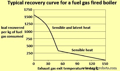
Gbr 1 Pemulihan energi dengan suhu keluar tumpukan yang berbeda
Ada tiga tantangan yang dihadapi oleh pemulihan panas suhu rendah. Tantangan-tantangan ini seperti yang diberikan di bawah ini.
- Ada korosi pada permukaan penukar panas. Saat uap air yang terkandung dalam gas buang mendingin, beberapa di antaranya mengembun dan mengendapkan padatan dan cairan korosif pada permukaan penukar panas. Penukar panas harus dirancang untuk menahan paparan terhadap endapan korosif ini. Hal ini biasanya membutuhkan penggunaan material yang canggih, atau penggantian komponen penukar panas yang sering, yang seringkali tidak ekonomis.
- Permukaan pertukaran panas yang besar diperlukan untuk perpindahan panas. Laju perpindahan panas adalah fungsi dari konduktivitas termal dari bahan penukar panas, perbedaan suhu antara dua aliran fluida, dan luas permukaan penukar panas. Karena panas buang suhu rendah melibatkan gradien suhu yang lebih kecil antara dua aliran fluida, luas permukaan yang lebih besar diperlukan untuk perpindahan panas. Ini membatasi keekonomisan penukar panas.
- Ada kebutuhan akan suhu panas yang rendah. Memulihkan panas dalam kisaran suhu rendah masuk akal hanya jika ada kebutuhan di pabrik untuk panas suhu rendah. Potensi penggunaan akhir adalah proses pemanasan suhu rendah. Pilihan lain termasuk menggunakan pompa panas untuk 'meningkatkan' panas ke suhu yang lebih tinggi untuk melayani beban yang membutuhkan suhu lebih tinggi. Selain itu, teknologi pembangkit listrik suhu rendah perlahan muncul.
Teknologi pertukaran panas suhu rendah
Teknologi pertukaran panas suhu rendah tersedia yang dapat mendinginkan gas di bawah suhu titik embun untuk memulihkan panas limbah suhu rendah. Pilihan teknologi termasuk deep economizers, pemulihan kondensasi kontak tidak langsung, pemulihan kondensasi kontak langsung, dan kondensor membran transpor yang dikembangkan baru-baru ini. Komersialisasi teknologi ini terbatas karena biaya tinggi dan karena fasilitas tidak memiliki penggunaan akhir untuk panas yang dipulihkan. Ketika fasilitas kekurangan penggunaan akhir untuk limbah panas, cara lain untuk pemulihan digunakan yang meliputi pompa panas dan pembangkit listrik suhu rendah. Teknologi ini juga sering dibatasi oleh kendala ekonomi.
Penghemat dalam – Deep economizers dirancang untuk mendinginkan gas buang hingga sekitar 70 derajat C dan untuk menahan endapan kondensat asam di permukaannya. Desain economizers dapat memiliki alternatif yang berbeda. Itu dapat memiliki pemasangan bagian 'sekali pakai' di ujung dingin economizer. Pipa di ujung dingin menurun seiring waktu dan perlu sering diganti. Frekuensi penggantian tergantung pada komposisi gas buang dan bahan konstruksi. Salah satu alternatifnya adalah merancang economizer dengan pipa stainless steel. Baja tahan karat dapat menahan gas asam lebih baik daripada baja ringan yang biasanya digunakan dalam konstruksi. Dalam desain lain, menggunakan baja C untuk sebagian besar penukar panas, tetapi menggunakan pipa baja tahan karat di ujung dingin di mana endapan asam terjadi. Penggunaan penukar panas pipa kaca (terutama untuk aplikasi gas-gas seperti pemanas awal udara) atau bahan canggih seperti Teflon dapat menjadi alternatif lain.
Pemulihan kondensasi kontak tidak langsung – Unit pemulihan kondensasi kontak tidak langsung mendinginkan gas hingga sekitar 40 derajat C. Dalam kisaran ini, uap air dalam gas mengembun hampir seluruhnya. Penukar kontak tidak langsung terdiri dari penukar panas shell and tube. Mereka dapat dirancang dengan baja tahan karat, kaca, Teflon, atau bahan canggih lainnya.
Pemulihan kondensasi kontak langsung – Pemulihan kondensasi kontak langsung melibatkan pencampuran langsung aliran proses dan cairan pendingin. Karena jenis pemulihan ini tidak melibatkan dinding pemisah di mana panas akan ditransfer, itu menghindari beberapa tantangan permukaan perpindahan panas besar yang diperlukan untuk unit pemulihan kontak tidak langsung. Dalam jenis pemulihan ini, saat gas buang memasuki penukar panas, mereka didinginkan oleh air dingin yang dimasukkan di bagian atas unit. Aliran air panas keluar melalui bagian bawah penukar dan memberikan panas ke sistem eksternal. Tantangan dengan kondensasi kontak langsung adalah air dapat terkontaminasi oleh zat dalam gas buang.
Transportasi kondensor membran – Transport membrane condenser (TMC) adalah teknologi yang sedang berkembang untuk menangkap air (bersama dengan panas laten air) dari uap air di aliran gas buang. Air diekstraksi dari gas buang pada suhu di atas titik embun dengan menggunakan kondensasi kapiler dan didaur ulang ke dalam air umpan boiler. Seperti dalam pemulihan panas kontak langsung, TMC mengekstrak air panas langsung dari gas buang. Namun, karena TMC memulihkan air melalui transportasi melalui membran, air yang dipulihkan tidak menjadi terkontaminasi seperti dalam pemulihan kontak langsung. Teknologi ini telah didemonstrasikan untuk aliran gas buang yang bersih dalam boiler berbahan bakar gas alam. Namun, TMC membutuhkan pengembangan lebih lanjut dalam material tingkat lanjut sebelum penerapan secara luas untuk aliran limbah yang lebih kotor dapat dilakukan.
Pompa panas atau peningkatan panas limbah suhu rendah – Teknologi pertukaran panas yang disebutkan di atas melibatkan aliran energi 'menurun' dari suhu tinggi ke penggunaan akhir suhu rendah. Hal ini dapat membatasi peluang untuk pemulihan panas ketika suhu panas limbah di bawah suhu yang dibutuhkan untuk beban pemanasan tertentu. Sebagai contoh, limbah panas dapat tersedia dalam bentuk air panas pada suhu sekitar 35 derajat C, sedangkan air panas pada suhu sekitar 85 derajat C dibutuhkan. Dalam kasus seperti itu, pompa panas dapat memberikan peluang untuk 'meningkatkan' panas ke suhu penggunaan akhir yang diinginkan. Pompa panas menggunakan input energi eksternal untuk menggerakkan siklus yang menyerap energi dari sumber suhu rendah dan menolaknya pada suhu yang lebih tinggi. Tergantung pada desainnya, pompa kalor dapat melayani dua fungsi. Mereka dapat meningkatkan panas limbah ke suhu yang lebih tinggi, atau menggunakan panas limbah sebagai input energi untuk menggerakkan sistem pendingin absorpsi. Pompa panas paling cocok untuk aliran produk suhu rendah yang ditemukan di industri proses.
Upgrade panas dapat ekonomis dalam beberapa kasus tergantung pada perbedaan suhu yang diperlukan dan biaya relatif bahan bakar dan listrik. Jika fasilitas memiliki beban panas pada suhu yang sedikit lebih tinggi daripada sumber panas limbah, panas kadang-kadang dapat diberikan lebih efisien oleh pompa panas daripada jika diperoleh dari pembakaran bahan bakar tambahan. Koefisien kinerja (COP) adalah ukuran kinerja pompa panas, ditentukan dari keluaran panas dan masukan kerja dan diberikan oleh persamaan COP =Q/W dimana Q adalah keluaran panas yang berguna dari pompa panas, dan W adalah masukan kerja.
Pertimbangan penting dalam menentukan kelayakan pompa kalor adalah suhu kalor buang dan kenaikan suhu yang diinginkan. Jenis siklus yang digunakan dan jenis fluida kerja yang dipilih mempengaruhi suhu di mana pompa kalor dapat menerima atau menolak panas, serta menentukan kenaikan suhu maksimum yang dapat dicapai. Efisiensi pompa kalor menurun seiring dengan kenaikan suhu yang diinginkan.
Siklus kompresi tertutup – Dalam siklus kompresi tertutup, pompa panas digunakan untuk menurunkan suhu air pendingin, sementara menggunakan panas yang diekstraksi untuk meningkatkan suhu air proses yang digunakan di tempat lain di pabrik. Pompa kalor terdiri dari evaporator, kompresor, kondensor, dan katup ekspansi. Di evaporator, energi ditransfer dari sumber panas limbah ke refrigeran. Kemudian refrigeran memasuki kompresor, di mana suhunya meningkat. Refrigeran superheated kemudian memasuki kondensor dan mentransfer panas ke heat sink. Terakhir, refrigeran dicekik dalam katup ekspansi sebelum kembali ke evaporator.
Rekompresi uap siklus terbuka – Rekompresi uap siklus terbuka menggunakan kompresi untuk meningkatkan tekanan (dan akibatnya suhu) dari uap limbah. Rekompresi uap mekanis menggunakan kompresor mekanis, sedangkan rekompresi uap termal menggunakan ejektor uap, dan karenanya digerakkan oleh panas daripada digerakkan secara mekanis
Pompa panas penyerapan – Pompa kalor absorpsi sangat mirip dengan siklus kompresi tertutup, kecuali kompresor digantikan oleh mekanisme absorpsi yang digerakkan oleh panas yang lebih kompleks. Tergantung pada kebutuhan pabrik, sistem dapat dikonfigurasi dalam berbagai cara. Dalam satu jenis, pompa kalor dapat menggunakan input kalor bersuhu lebih rendah dan lebih tinggi untuk menolak kalor pada tingkat menengah (misalnya meningkatkan kalor bersuhu rendah). Pada tipe lain, pompa kalor dapat menggunakan input suhu sedang untuk menolak panas dalam satu aliran suhu yang lebih rendah dan satu aliran suhu yang lebih tinggi. Aplikasi kedua ini dapat digunakan untuk AC dan/atau refrigerasi.
Pembangkit listrik
Membangkitkan tenaga dari limbah panas biasanya melibatkan penggunaan panas buangan dari boiler untuk menciptakan energi mekanik yang kemudian menggerakkan generator listrik. Siklus daya ini berkembang dengan baik. Namun, teknologi baru sedang dikembangkan yang dapat menghasilkan listrik langsung dari panas, seperti pembangkit termoelektrik dan piezoelektrik. Ketika mempertimbangkan teknologi pembangkit listrik untuk WHR, faktor penting yang harus diingat adalah batasan termodinamika pada pembangkit listrik pada suhu yang berbeda. Efisiensi pembangkit listrik sangat tergantung pada suhu sumber panas limbah. Secara umum, pembangkit listrik dari limbah panas terbatas hanya pada sumber panas limbah suhu sedang hingga tinggi. Namun, kemajuan dalam siklus daya alternatif dapat meningkatkan kelayakan pembangkitan pada suhu rendah. Meskipun efisiensi maksimum pada suhu ini lebih rendah, skema ini tetap ekonomis dalam memulihkan energi dalam jumlah besar dari limbah panas.
Tiga metode untuk menghasilkan tenaga dengan menggunakan energi mekanik dijelaskan di bawah ini.
Siklus Steam Rankine – Sistem yang paling sering digunakan untuk pembangkit listrik dari limbah panas melibatkan penggunaan panas untuk menghasilkan uap, yang kemudian menggerakkan turbin uap. Siklus Rankine steam tradisional adalah pilihan yang paling efisien untuk pemanfaatan kembali limbah panas dari aliran pembuangan dengan suhu di atas 340 derajat C. Pada temperatur limbah panas yang lebih rendah, siklus steam menjadi lebih hemat biaya, karena steam bertekanan rendah membutuhkan peralatan yang lebih besar. Selain itu, limbah panas suhu rendah tidak dapat menyediakan energi yang cukup untuk memanaskan uap, yang merupakan persyaratan untuk mencegah kondensasi uap dan erosi bilah turbin. Oleh karena itu, aplikasi pemulihan panas suhu rendah lebih cocok untuk Siklus Rankine organik atau siklus Kalina, yang menggunakan cairan dengan suhu titik didih lebih rendah dibandingkan dengan uap.
Siklus Rankine Organik – Siklus Rankine organik (ORC) beroperasi mirip dengan siklus Rankine uap, tetapi menggunakan fluida kerja organik bukan uap. Alternatif termasuk minyak silikon, propana, halo-alkana (misalnya freon), iso-pentana, iso-butana, p-xilena, dan toluena, yang memiliki titik didih lebih rendah dan tekanan uap lebih tinggi daripada air. Hal ini memungkinkan ORC beroperasi dengan suhu panas limbah yang jauh lebih rendah. Kisaran suhu yang paling tepat tergantung pada fluida yang digunakan, karena sifat termodinamika fluida mempengaruhi efisiensi siklus pada berbagai suhu. Dibandingkan dengan uap air, fluida memiliki massa molekul yang lebih tinggi, memungkinkan desain yang kompak, aliran massa yang lebih tinggi, dan efisiensi turbin yang lebih tinggi. Namun, karena ORC berfungsi pada suhu yang lebih rendah, efisiensi keseluruhannya rendah dan bergantung pada suhu kondensor dan evaporator. Meskipun efisiensinya lebih rendah daripada pembangkit listrik tenaga uap suhu tinggi, penting untuk diingat bahwa siklus suhu rendah secara inheren kurang efisien daripada siklus suhu tinggi. Batas efisiensi dapat dinyatakan menurut efisiensi Carnot yang merupakan efisiensi maksimum yang mungkin untuk mesin kalor yang beroperasi antara dua suhu. A Carnot engine operating with a heat source at 150 deg C and rejecting it at 25 deg C is only about 30 % efficient. In this light, a low efficiency in the range of 10 % to 20 % in case of ORC is a substantial percentage of theoretical efficiency, especially in comparison to other low temperature alternatives, such as piezoelectric generation, which are only 1 % efficient.
Although the economics of ORC, heat recovery need to be carefully analyzed for any given application, it is a useful alternative in those industries which do not have in-house use for additional process heat or no neighbouring plants which can make economic use of the heat.
Kalina cycle – The Kalina cycle is a variation of the Rankine cycle, using a mixture of ammonia and water as the working fluid. A key difference between single fluid cycles and cycles which use binary fluids is the temperature profile during boiling and condensation. For single fluid cycles, the temperature remains constant during boiling. As heat is transferred to the working medium (water), the water temperature slowly increases to boiling temperature, at which point the temperature remains constant until all the water has evaporated. In contrast, a binary mixture of water and ammonia (each of which has a different boiling point) increases its temperature during evaporation. This allows better thermal matching with the waste heat source and with the cooling medium in the condenser. Consequently, these systems achieve considerable greater energy efficiency. The cycle was invented in the 1980s.
Direct electrical conversion technologies
Whereas traditional power cycles involve using heat to create mechanical energy and ultimately electrical energy, new technologies are being developed which can generate electricity directly from heat. These include thermoelectric, thermionic, and piezoelectric technologies. However, these technologies are in development stage. A few have undergone some prototype testing in applications such as heat recovery in automotive vehicles.
Thermoelectric generation – Thermoelectric (TE) materials are semiconductor solids which allow direct generation of electricity when subject to a temperature differential. This technology is based on a phenomenon known as the Seebeck effect which states that when two different semiconductor materials are subject to a heat source and heat sink, a voltage is created between the two semi-conductors. Conversely, TE materials can also be used for cooling or heating by applying electricity to dissimilar semiconductors. Thermoelectric technology has existed for a long time (the thermoelectric effect was first discovered in 1821), but has seen limited use due to low efficiencies and high cost. Most TE generation systems in use have efficiencies in the range of 2 % to 5 %. These have mainly been used to power instruments on spacecraft or in very remote locations. However, recent advances in the nano-technology have enabled advanced TE materials which can achieve conversion efficiencies 15 % or higher.
In a recent study, it has been concluded that advanced TE packages are appropriate in medium to high temperature, high flow rate exhaust streams where facilities have little use for recovered waste heat. However, more development work is needed in this area. Low cost, high volume production methods for TE materials need to be developed in order to achieve this goal. Also, maintaining a high temperature differential across thin TE devices present a significant engineering challenge. Obtaining high heat transfer rates require advances in heat transfer materials and heat exchange systems with high heat transfer coefficients.
Piezo-electric power generation Piezo-electric power generation (PEPG) is an option for converting low temperature waste heat in the range of 100 deg C to 150 deg C to electrical energy. Piezo-electric technology converts mechanical energy in the form of ambient vibrations to electrical energy. A piezo-electric thin film membrane can take advantage of oscillatory gas expansion to create a voltage output. However, there are several technical challenges associated with PEPG technologies. These include (i) low efficiency (only around 1 % efficient), (ii) difficulties remain in obtaining high enough oscillatory frequencies (current devices operate at around 100 Hz, and frequencies needed are close to 1,000 Hz), (iii) high internal impedance, (iv) complex oscillatory fluid dynamics within the liquid/vapour chamber, (v) need for long term reliability and durability, and (vi) high costs.
While the conversion efficiency of PEPG technology is currently very low (1 %), there can be prospects to use PEPG cascading, in which case efficiencies can reach about 10 %. Other key issues are the costs of manufacturing piezoelectric devices, as well as the design of heat exchangers to facilitate sufficient heat transfer rates across a relatively low temperature difference.
Thermionic generation – Thermionic devices operate similar to thermo-electric devices. However, whereas thermoelectric devices operate according to the Seebeck effect, thermionic devices operate via thermionic emission. In these systems, a temperature difference drives the flow of electrons through a vacuum from a metal to a metal oxide surface. One key disadvantage of this technology is that it is limited to applications with high plying electricity to dissimilar semiconductors. Thermo-electric technology has existed for temperatures above 1,000 deg C. However, some development has enabled their use at around 100 deg C to 300 deg C range.
Thermo photo voltaic generator Thermo photo voltaic generators can be used to convert radiant energy into electricity. This technology involves a heat source, an emitter, a radiation filter, and a photo voltaic (PV) cell (like those used in solar panels). As the emitter is heated, it emits electro-magnetic radiation. The PV cell converts this radiation to electrical energy. The filter is used to pass radiation at wave-lengths which match the PV cell, while reflecting remaining energy back to the emitter. This technology can potentially enable new methods for WHR. A small number of prototype systems have been built for small burner applications and in a helicopter gas turbine.
WHR and iron and steel industry
The iron and steel industry employs several high temperature furnaces for coke, sinter, hot metal, and steel production and accounts for high energy consumption. While recovery from clean gaseous streams in the industry is common, heavily contaminated exhaust gases from coke oven, blast furnace (BF), basic oxygen furnace (BOF), and electric arc furnace (EAF) continues to present a challenge for economic WHR. Heat recovery techniques from these dirty gaseous streams are available, yet implementation has been limited due to high capital investment costs.
The steel industry has made the biggest progress in reducing its energy intensity. Such progress has been achieved by continuous casting and optimization of BF operation, and also through steel recycling and replacement of fossil fuels with recycled by-product gases (coke oven gas, blast furnace gas, and converter gas). In-situ waste heat recovery has been implemented wherever possible, for example, by recirculating hot flue gases inside the furnace where they were created to lower external energy demand, or by using hot flue gases to preheat combustion air or fuel gas. Such energy efficiency improvements still leave residual waste heat recovery opportunities, e.g. to produce steam for other parts of the process or to produce electricity.
WHR in case of steel plants is described below.
Coke production
Production of coke is an essential burden material for BF operation. Coke is produced in coke ovens, where coal is heated in an oxygen limited atmosphere. There are two methods for producing coke namely (i) the byproduct process, and (ii) the non-recovery process. In the byproduct process, chemical byproducts (crude tar, ammonia, and light oils) in the coke oven gas are recovered, while the remaining coke oven gas (COG) is cleaned and recycled within the steel plant. In the non-recovery process, the entire COG is burned in the process. The most common type of process is still the byproduct process and this is discussed below.
Byproduct cokemaking process has two areas of sensible heat loss namely (i) COG which is cooled in the gas cleaning process, and (ii) waste gas leaving the coke oven. The coke making process employs several coke oven chambers separated by heating flues. Recycled COG, and sometimes other gases such as BF gas, are used as the fuel source in the heating flue and supply heat to the oven chamber where coal carbonization takes place. As coal is carbonized in the oven chamber, gas and moisture (accounting for around 8 % to 11 % of charged coal) are driven off and leave through the pipes. The COG has a high heat content ranging from around 4000 kcal/cum to 4400 kcal/cum and hence it can be recycled for use as a fuel after undergoing a cleaning process.
The temperature of the crude COG at the oven outlet ranges from 650 deg C to 1000 deg C.
At this point, the COG gas is a source of sensible heat. However, the heat is universally wasted due to the high amount of tar and other materials which can cause build up on heat exchanger surfaces. Upon leaving the oven, the COG is cooled by ammonia liquor spray followed by primary coolers. Different technologies are then used for removing tar, sulphur compounds, ammonia, and light oils. After cleaning, the COG is used as a fuel throughout the steel plant. In this arrangement, only the chemical energy of the COG is recovered when recycled, while the sensible heat is wasted.
While most of the steel plants do not employ heat recovery from COG, a limited level of heat recovery from COG is possible, as shown by the success of this practice in Japan. Coke oven facilities in Japan have successfully applied heat recovery through use of a low pressure heat transfer medium. In general, the minimum allowable temperature for the COG in the heat exchanger is around 450 deg C. At lower temperatures, tar condenses and leads to soot formation on the heat exchanger surface.
Cooling to 450 deg C enables only about one third of the sensible heat to be recovered. However, it is unlikely that ISPs in other countries are going to pursue new technologies for heat recovery from crude coke oven gas. This is since ISPs are facing cost barriers with heat recovery from dirty exhaust streams. Also, the byproduct coke making process can become irrelevant in future years. It is likely that the ISPs are going to move away from the byproduct process to the non-recovery process due to environmental considerations. In the non-recovery process, the COG gas is burned within the process, and a WHB used to recover the sensible heat in the off gases.
Another source of sensible heat loss in coke ovens is the waste gases from the combustion of recycled fuel gases. The recycled fuel gases are used in the heating flue, which is adjacent to the oven chamber. Combustion of the fuel gases generates hot exhaust gases which leave the oven flue and pass through a regenerator to transfer heat to incoming combustion air and/or fuel. Waste gases leave the regenerator at temperatures averaging around 200 deg C. In some plants, the heat content of the waste gases are further recovered by use of a heat pipe or for preheating coal charge and reducing its moisture content. In this case, the temperature of the exhaust gases drops to around 60 deg C.
Production of sinter
Sintering plant consists of two major sections, sintering section and sinter cooling section. Heat recovery from both parts has been developed namely (i) from sintering section exhaust gas, and (ii) from cooling section cooling gas. There is large temperature difference depending on the position of the section. Average gas temperature in both sections is in the level of 100 deg C to 150 deg C, too low for effective heat recovery. Heat recovery is to be limited to high gas temperature zone, the final part of sintering section and primary part of cooling section, where gas temperatures of 300 deg C or higher are available. Although heat recovery zone is limited, the gas volume of sintering process is large enough for practical heat recovery.
The waste gas energy recovery system consists of hood, dust catcher, heat recovery boiler, circulation fan and de-aerator. Sintering machine exhaust gas is corrosive containing some dusts. Heat recovery is generally limited to high gas temperature zone as aggregated average temperature is low for heat recovery. At the same time, due to its corrosiveness, the gas temperature after heat recovery is to be kept above acid due point of the gas. Cooling gas is basically atmosphere air containing some dust. In case of sinter cooler, it is same as sintering machine heat recovery. Due to gas temperature distribution along with the cooler, heat recovery is limited to high gas temperature zone.
Sintering machine exhaust gas heat recovery can be categorized to circulation type and non-circulation type. In circulation type, gas after heat recovery are circulated to sintering machine as cooling gas replacement, whereas in non-circulation type, the gas after heat recovery is lead to gas treatment facility directly. Jenis sirkulasi diadopsi untuk meningkatkan efisiensi pemulihan panas.
In case of cooler heat recovery, the cooler gas is air. The cooler heat recovery system can be categorized as circulation type and non-circulation type. In case of non-circulation type, after heat recovery from hot gas zone, cooling gas is released to the atmosphere. In case of circulation type, after heat recovery from hot gas zone, cooling gas is led to cooler and reused for sinter cooling. Cooler gas temperature rises through recirculation and consequently results to higher heat recovery. On the other hand, cooling gas temperature rises up to the level of 180 deg C, cooling capability can decrease. Sinter temperature at outlet of the cooler is higher around 30 deg C in circulation type. Temperature difference is small enough and does not affect sinter plant operation. Recovered energy increases by 50 % in circulation type compared to non-circulation type. Fan power consumption is larger in case of circulation type. However, recovered power is far larger.
Hot metal production in BF
BF is one of the main units in ISPs. It converts iron ore into hot metal. Raw materials are charged from the top, including iron containing materials (lump iron ore, sinter, or pellets), additives (flux), and coke, while hot air and supplemental fuels are injected through tuyeres at the bottom of the furnace. The burden moves down through the BF and meets a rising current of hot gases. The hot air entering the BF is provided by several auxiliary hot blast stoves. In the hot blast stove, mixed gas consisting of BF gas (BFG) and COG are combusted. The heat from the combustion exhausts is transferred to a checker work regenerator. When the regenerator reaches an appropriate temperature, the flow of air is reversed and cold air is forced through the regenerator, which transfers heat to the cold air. The heated air is then injected into the furnace. The system operates according to the same principles as a regenerator used for heat recovery. However in this case, the regenerator is not a waste heat recovery unit, but rather the mechanism for transferring heat from the stove to the hot blast. Sources of off gas waste heat in BF include both the exhaust gases from the hot blast stove and the BFG leaving the BF.
There is sensible heat loss from BFG. New BFs are designed for efficient heat transfer, resulting into hot gases at the BF top in the low temperature range. The BFG is recovered for use as a fuel in blast air heating, rolling mill reheating furnaces, coke oven heating, power production, and steam generation. Since BFG has low calorific value, it is often mixed with COG or converter gas. BFG is required to be cleaned before it can be used as a fuel, and the sensible heat contained in the gas is rarely recovered. In some cases, BF operates at a sufficiently high pressure (2.5 atm or higher) to economically use a top pressure recovery turbine (TRT) for recovering of the pressure energy of the BFG. The gas is to be cleaned before entering the TRT, which is generally accomplished via wet cleaning, with the result that sensible heat of the off gas is lost. An alternative to wet cleaning technology is dry cleaning, in which the temperature of the gas entering the TRT can be raised to around 120 deg C. Dry type TRT technology is already working in several places. However, it is more expensive.
Another opportunity for WHR is from the combustion exhaust gases leaving hot blast stoves. The gases are at temperatures of around 250 deg C. The blast stove exhaust gas is relatively clean and is more compatible with heat recovery devices, making heat recovery from blast stoves a more common practice. The heat can be used to preheat combustion air and/or fuel gas. Heat exchangers used include rotary regenerators, fixed plate heat exchangers, and circulating thermal medium systems.
Production of liquid steel in BOF
BOF uses oxygen to oxidize impurities in the hot metal. Operation is semi-continuous:hot metal and scrap are charged to the furnace, oxygen is injected, fluxes are added to control erosion, and then the metal is sampled and tapped. The temperature required to melt the metal is supplied by the exothermic oxidation reaction and hence, no external heat source is needed.
The off gases from the BOF are at a high temperature. It has a high concentration of CO (carbon monoxide). Like COG and BFG, BOF gases offer opportunities for recovery of chemical energy and sensible heat. Challenges to WHR include high capital costs and the substantial maintenance problems resulting from hot dirty gases. Contaminants include iron oxides, heavy metals, SOx, NOx, and fluorides.
Various commercial methods for WHR are available. The two main methods for heat recovery are open combustion and suppressed combustion. In open combustion systems, air is introduced to the BOF gas duct to combust the CO. The heat generated is recovered with a waste heat boiler. In the suppressed combustion method, a skirt is added to the converter mouth to reduce air infiltration and combustion of the CO. The gas is then cleaned, collected, and used as a fuel. It is also possible to recover both the gas and the sensible heat via a combined boiler/suppressed combustion gas recovery system.
Liquid steel production by EAF
The steel industry has experienced significant growth in manufacture from recycled scrap via electric smelting. EAF and induction furnace are the two types of furnaces used to melt ferrous scrap for electric smelting. Out of these two, EAF is the prominent furnace. The furnace is refractory lined and typically covered by a retractable roof, through which C electrodes are lowered. Charge materials are lowered through the roof. Fluxes and alloying agents are also added to help control the quality of the material. The electrodes are then lowered to about an inch above the metal, and the current provides heat for melting the scrap. During furnace operation, several gases and particulate emissions are released, including CO, SOx, NOx, metal oxides, volatile organic compounds (VOCs), and other pollutants. Off gas temperatures at peak loads can equal anywhere from 1,350 deg C to 1,950 deg C. Exhaust gases are responsible for losses of around 20 % of the power input. Half of these losses are due to the chemical energy in the gases, while the other half is sensible heat. Additionally, around 8 % to 10 % of energy input is also lost to EAF cooling water jacket.
The most common method for heat recovery is scrap preheating, which has been widely used. The use of off gases to preheat scrap can save from 5 % to 10 % of total EAF energy consumption. Initial designs for scrap preheat required piping off gases to the charging bucket. Some of the challenges with these systems include the need to transport preheated scrap containing semi-burned non scrap materials (e.g., plastics), as well the evaporation of volatiles which create odour and environmental control problems. Alternatives to the bucket preheating system include the Consteel process, the Fuchs shaft furnace, and the Twin shell furnace. These processes have been installed at various places.
The Consteel process involves continuous charging of scrap and uses a scrap conveyer, a feeding system, and a preheater. The preheater is a refractory lined tunnel where off gases flow opposite the flow of scrap charge. Air is introduced into the preheater to burn the CO and CO2 and thus both the chemical and sensible heat in the off gas is used. An afterburner is sometimes installed to burn remaining CO and other compounds.The Fuchs shaft furnace involves a shaft immediately above the arc furnace roof. The charge is loaded via baskets in three stages. The baskets are refractory lined and designed with a seal which prevents the escape of fumes. Scrap heating is further assisted by auxiliary oxy-fuel burners. Additionally, afterburners are installed to completely combust all the CO. One additional benefit of the system is that charge acts as a dust filter, capturing around 40 % of the dust and returning it to the furnace, thus enabling slight increases in yield.
The benefits and drawbacks of scrap preheating systems depend on the specific operation. In some cases, it enables reduced electricity consumption and increased productivity. In other cases, scrap preheating systems are difficult to maintain. As EAFs become increasingly efficient and tap to tap times are reduced, scrap handling can reduce productivity and possibly create burdensome maintenance demands. In one case, the energy savings enabled by scrap preheating are reduced by about one half when tap to tap times are reduced by a third.
Power plant boilers
Boilers in ISPs normally use BFG and COG as fuel. The exhaust gas temperature for the boilers varies with the boiler’s age and the controls used. Temperatures can be fairly high (340 deg C to 450 deg C), with O2 content varying from 3 %7.5 %. The waste heat is in the form of clean, contamination-free gases and does not require further conditioning. The areas of waste heat and recovery from boilers and steam systems include (i) use of exhaust gases to preheat BFG and COG, (ii) use of low-temperature power generation if economically justifiable, (iii) preheating service water or river water for use in the plant, if possible and required, and low-pressure steam can be condensed and reused for the boiler water system instead of venting.
Reheating furnace
Reheating furnace is a key equipment of the hot rolling mills. Its function is to continuously heat billets, slabs or blooms of different sizes and grades upto 1,250 deg C. Most of the new reheat furnaces are walking beams furnaces (WBF). On the WBF, the heating is done over and under the products which are handled from charging side to discharging side by means of insulated and cooled beams (skids). A key performance criterion for reheating furnaces is heating homogeneity. 20 % to 30 % of the energy input is typically wasted divided between several thermal losses namely (i) the temperature of the exhaust gas between the combustion air recuperator and the stack is at 250 deg C to 300 deg C with natural gas fuel and higher with lower calorific value fuel, (ii) the product handling systems inside the furnace with skids and post cooling system, and (iii) wall and doors losses, hardly recoverable.
Water is used to constantly cool the skid system which is in contact with a very hot atmosphere in the furnace. This water loop typically enters at 40 deg C and is heated by 15 deg C before being directed to a dedicated cooling system.
At several places, WHR is carried out on the skid cooling system by producing steam when it is needed in the plant for other purposes. On its own, this installation reduces losses through the skid system because of the use of water cool pipes used at higher temperature. If steam is not needed by the plant then an ORC (adapted for such temperatures around 200 deg C) can be installed on the steam circuit to produce electricity. This installation has the benefit of being easily and safely operable especially with high variability of the losses because of the constant temperature brought by the water phase change. Most of the time, this technology is not installed because of long payback, and the energy contained in exhaust gases is wasted.
An electricity production system is possible to recover energy from exhaust gases. Depending on the heat source temperature, either a water-steam cycle (with low efficiency furnace) or an ORC (with better efficiency) are available. However, most of the time those technologies are not installed because of their long payback. This situation can have another solution. This solution combines heat from the skid cooling loop operated at higher pressure and temperature so as to produce a mixture of steam and water at around 215 deg C in a closed loop and heat from exhaust gases. The two heat sources are recovered separately thanks to organic heat fluid loops and then combined to form a common heat source.
The heat fluctuation from the exhaust gases (temperature and volume are modified) in case of furnace power variations (production or product variations) are balanced because of the constant temperature of the heat coming from the skid cooling system. Thus operation of the system is easy and makes the global heat source more stable especially with high fluctuations.
It is possible that the reheat furnace production can fluctuate in few minutes, which affects the heat content of exhaust gases entering the WHR system. The ORC is a rather flexible system which can accommodate such variations upto a certain point. An ORC can typically operate down to 30 % of its nominal capacity, and automatically shuts down when the heat input goes below that threshold. However, the economic aspect is affected as electricity production also decreases as well.
Heat storage solutions can be adapted to daily variations are becoming available for industrial applications and can be used in combination with an ORC to flatten its production. Oil is, for instance, is appropriate heat storage medium at that temperature level. Economic benefits need to be assessed on a case by case basis.
Waste heat from solid streams
In addition to waste heat losses from off gases, solid streams and cooling water are sources of additional sensible heat losses. Solid products and byproducts with significant waste heat losses include hot coke, hot sinter, BF slag, BOF slag, cast steel, and hot rolled steel. Though the heat from solid streams are often more difficult to recover, the heat losses are high. The sensible heat loss from coke is recovered in some plants coke dry quenching (CDQ) as an alternative to wet quenching. CDQ involves catching incandescent coke in a specially designed bucket, which is discharged into the CDQ vessel. An inert gas such as nitrogen passes over the coke and recovers its sensible heat. The hot gas is then passed through a waste heat boiler. Energy saving is in the range of 0.2 million to 0.25 million kcal per ton of coke. There have also been attempts to recover heat from other solid flows via radiant heat boilers. This was unsuccessful for BF and BOF slag, but has been commercialized for recovering heat from cast steel in a few locations in Japan and Germany.
Another option for reducing heat losses from cast steel is hot charging, in which cast products are charged to the reheating furnace while still hot. Hot charging can save about 0.12 million kcal per ton. Sensible heat loss from hot rolled steel can also be partially recovered by using water cooling. Since the final temperature of the cooling water is generally low (around 80 deg C), it can be upgraded for other heating applications with a heat pump.


