Aspek penting dari desain Blast Furnace dan peralatan tambahan terkait
Aspek penting desain Blast Furnace dan peralatan tambahan terkait
Desain tanur sembur (BF) yang tepat dan peralatan terkait dan tambahannya (Gbr 1) langsung ke hulu dan hilir tanur penting untuk menjalankan BF secara efisien. Selain tungku yang tepat, peralatan terkait langsung meliputi (i) gudang penyimpanan, (ii) peralatan pengisian, (iii) bagian atas tungku, (iv) sistem pendingin, dan (v) peralatan area rumah tuang.
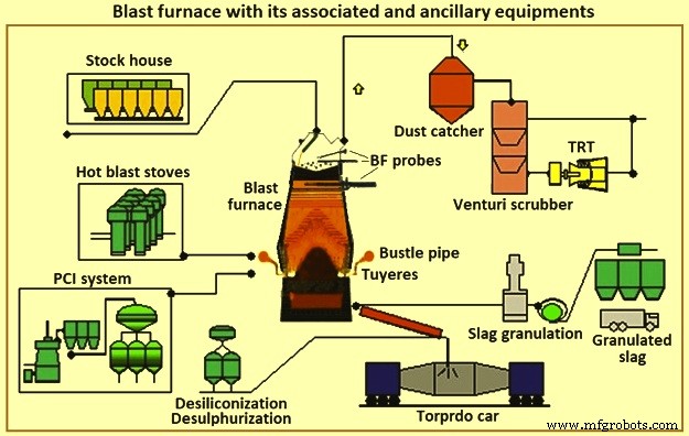
Gbr 1 Tungku sembur dengan peralatan terkait dan pelengkapnya
Pembuatan besi BF terdiri dari sistem yang terdiri dari beberapa komponen yang berfungsi secara harmonis. Aplikasi dan pengoperasian yang tepat dari komponen-komponen ini diperlukan untuk mendukung proses pembuatan besi. Pemilihan komponen tertentu tergantung pada faktor-faktor seperti kondisi yang ada, kendala fisik, persyaratan produksi, biaya, jadwal, keandalan, dan pemeliharaan. Saling ketergantungan komponen sama pentingnya dengan keberhasilan operasi sistem sebagai kemampuan masing-masing. Ada persyaratan utama dan praktik 'normal' untuk setiap area atau komponen. Ada juga beberapa teknologi alternatif yang tersedia secara komersial yang memiliki kelebihan dan kekurangan.
BF mengubah beban bijih bantalan besi menjadi besi cair (logam panas). Terkait dengan BF adalah baterai oven kokas yang mengubah batubara menjadi kokas, dan pabrik sinter dan pelet, yang menyiapkan bijih besi untuk BF. BF mengubah bahan mentah yang disiapkan ini menjadi produk yang bernilai lebih tinggi. Logam panas dari beberapa operasi BF digunakan dalam pengecoran untuk produksi besi tuang. Operasi lain menghasilkan logam panas silikon yang lebih rendah yang diubah menjadi baja di toko peleburan baja. Beberapa logam panas diubah menjadi pig iron di mesin pig casting. Hasil samping BF adalah slag, gas atas BF, debu asap, dan filter cake. Produk sampingan ini dapat memiliki dampak ekonomi positif atau negatif, tergantung pada kemungkinan pemanfaatan lokal.
Beberapa dari beberapa aspek yang mempengaruhi setiap pertimbangan untuk desain atau desain ulang BF adalah (i) keuntungan, (ii) kesehatan dan keselamatan karyawan, (iii) perlindungan lingkungan, (iv) peraturan perundang-undangan, (v) kebutuhan pasar dan pemrosesan hilir, (vi) sumber daya manusia, konstruksi, dan pemeliharaan yang tersedia, (vii) perubahan teknologi dan keusangan peralatan, (viii) ketersediaan bahan mentah, utilitas, dan bahan lainnya, dan (ix) seterusnya. Setiap kendala serius dalam salah satu aspek ini dapat membahayakan kelangsungan hidup unit BF (atau bahkan pabrik baja) atau menghalangi atau mengharuskan pembangunan BF baru.
BF biasanya dikelompokkan berdasarkan ukuran. Mini BF menghasilkan kurang dari 1.500 ton logam panas per hari (tHM/hari), BF kecil menghasilkan dalam kisaran sekitar 2.500 tHM/hari hingga 5.000 tHM/hari, BF menengah menghasilkan dalam kisaran sekitar 6.000 tHM/hari hingga 8.000 tHM/hari, dan BF besar menghasilkan sekitar 9.000 tHM/hari hingga 12.000 tHM per hari. Di pabrik baja terintegrasi, sejumlah dan ukuran BF diperlukan untuk menyediakan logam panas yang dibutuhkan untuk produksi baja. Pabrik baja terintegrasi dengan sejumlah BF kurang terpengaruh saat BF menjalani perbaikan pelapisan ulang atau saat ada masalah kontrol tungku. BF kecil memiliki perbaikan pelapisan ulang yang lebih pendek daripada BF besar dan dianggap lebih mudah dioperasikan. Namun, biaya logam panas dari BF kecil lebih tinggi. Pabrik baja terintegrasi diperlukan untuk mengoperasikan jumlah minimum tungku hemat biaya. Dalam beberapa kasus, peningkatan dilakukan untuk mengurangi jumlah tungku yang beroperasi.
BFs secara berkala relining setelah akhir kampanye (waktu antara perbaikan relining). Di masa lalu, ini melibatkan penggantian lapisan bata internal tungku utama. Belakangan ini, pembangunan kembali komponen secara ekstensif, penggantian, dan pemeliharaan preventif dilakukan secara bersamaan. Dengan praktik ini, pabrik baja yang lebih efisien dengan BF besar yang lebih sedikit kehilangan persentase yang lebih tinggi dari produksinya selama perbaikan pelapisan ulang BF daripada pabrik dengan jumlah tungku kecil yang lebih banyak. Untuk mendapatkan biaya pengoperasian yang rendah dan gangguan minimum selama pelapisan ulang BF, industri telah bekerja untuk memaksimalkan kampanye BF dan untuk mengurangi durasi perbaikan pelapisan ulang. Tren yang jelas saat ini di pabrik baja terintegrasi adalah mengoperasikan lebih sedikit tungku besar dan menggunakan teknik dan desain yang memperpanjang kampanye BF tanpa batas.
Pada saat yang sama, pengurangan variabilitas produk menjadi lebih penting, dan karenanya investasi dilakukan dalam otomatisasi yang meningkatkan pemantauan dan pengendalian proses. Operator BF, personel pemeliharaan, perancang, dan personel riset telah menerapkan teknologi modern dan metode analitik pada proses BF untuk memantau dan mengontrol proses dengan lebih baik. Akibatnya, standar deviasi kualitas logam panas telah berkurang. Sistem pengumpulan data yang ditingkatkan juga memberikan peningkatan informasi bagi pemasok dan produsen. Ini telah meningkatkan pemilihan bahan dan desain BF dan peralatan terkait. Durasi kampanye telah meningkat menjadi sekitar 20 tahun sebelumnya dari 5 tahun menjadi 10 tahun.
Pembuatan besi BF adalah teknologi berusia 430 tahun lebih. Meskipun demikian, penggunaan logam panas BF masih merupakan metode yang paling umum digunakan di pabrik baja terintegrasi untuk produksi baja. Proses pabrik baja terintegrasi saat ini mengandalkan BF untuk menyediakan jumlah logam panas yang dapat diprediksi dengan kualitas yang konsisten sesuai jadwal. Variasi dalam salah satu aspek pasokan logam panas memiliki dampak serius pada sisa proses produksi baja. Oleh karena itu, BF terus menjadi proses utama di pabrik baja terintegrasi modern.
Kadang-kadang dinyatakan bahwa teknologi proses BF berada di akhir masa pakainya. Ini tidak begitu. Studi tentang data operasi selama 23 tahun (1970 hingga 1993) dari sepasang BF ukuran sedang yang khas telah menunjukkan bahwa ada peningkatan rata-rata produktivitas sebesar 3% per tahun (Gbr 2a). Pada saat yang sama, penurunan rata-rata tingkat bahan bakar adalah 1% per tahun (Gbr 2b). Juga, waktu produktif antara pelapisan ulang BF (kampanye) telah diperpanjang melalui perbaikan peralatan, bahan, dan desain. Akibatnya, biaya keseluruhan untuk memproduksi logam panas, yang dikoreksi karena inflasi, telah meningkat bahkan lebih dari yang ditunjukkan oleh data operasi. Oleh karena itu, teknologi proses BF tidak mati meskipun merupakan teknologi berusia 430 tahun lebih. Hal ini masih berkembang di setiap daerah pada tingkat yang cukup besar. BF saat ini tetap menjadi ilmu yang dinamis yang didukung oleh teknologi yang terus meningkat.
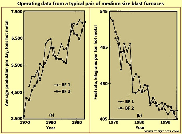
Gbr 2 Data pengoperasian dari sepasang tanur sembur ukuran sedang pada umumnya
Tata Letak BF
Tata letak BF pada dasarnya adalah latihan mengintegrasikan peralatan yang dibutuhkan untuk menangani berbagai bahan yang dibutuhkan untuk membuat logam panas dan produk yang dihasilkan serta produk sampingan. Desain yang paling efisien dengan tepat mengakomodasi seluruh proses dan efektivitasnya dinilai dari sudut pandang investasi modal awal dan biaya operasi yang berkelanjutan. Tata letak toko BF bergantung pada beberapa faktor seperti (i) medan lokasi, (ii) kondisi iklim, (iii) metode pengiriman bahan baku, (iv) sistem dan lokasi pemrosesan bahan baku di pabrik, (v) sistem pemrosesan hilir dan lokasi, (vi) kuantitas/persyaratan aliran untuk logam panas, (vii) jenis dan ukuran armada pengiriman logam panas, dan (viii) seterusnya. Gambar 3 menunjukkan tata letak pabrik BF yang disederhanakan.
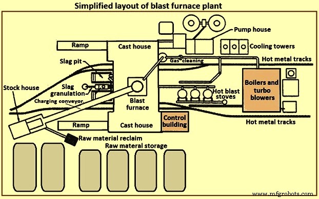
Gbr 3 Tata letak sederhana dari pabrik tanur tinggi
Sebuah pabrik BF biasanya terdiri dari beberapa bagian. Bagian-bagian ini adalah (i) penyimpanan, penanganan, dan reklamasi bahan baku, (ii) gudang penyimpanan, (iii) sistem pengisian, (iv) tungku yang tepat, (v) rumah cor, (vi) pemrosesan dan penanganan terak, (vii) penanganan logam panas, (viii) kompor sembur panas dan sistem semburan panas, (ix) pabrik pembersihan gas, (x) utilitas, (xi) sistem otomasi dan kontrol, (xii) fasilitas pemeliharaan, dan (xiii) fasilitas pendukung personel.
Penyimpanan dan penanganan bahan mentah
Bahan baku seperti bijih besi, sinter, pelet, fluks, batu bara, dan kokas dll diterima baik dari sumber eksternal atau diproduksi di dalam pabrik baja terintegrasi. Bahan baku ini membutuhkan penyimpanan terkontrol yang cukup untuk mendukung operasi BF. Kapasitas penyimpanan diperlukan jika terjadi gangguan pengiriman yang dapat diprediksi atau gangguan yang tidak dapat diprediksi. Kapasitas penyimpanan tambahan dapat diperlukan jika ada kemungkinan perubahan pada sumber bahan baku tertentu. Lokasi penyimpanan yang terpisah diperlukan karena karakteristik fisik atau kimia yang berbeda pada bahan yang sejenis. Pencampuran bahan serupa dapat menyebabkan kontrol proses / masalah metalurgi. Tumpukan penyimpanan harus dipisahkan untuk mencegah bercampurnya bahan yang berbeda. Tumpukan harus ditempatkan pada tempat tidur yang telah disiapkan untuk memungkinkan operator peralatan reklamasi bahan baku membedakan antara bahan utama dan bahan gelandangan. Tiang pancang diletakkan untuk meminimalkan degradasi material dan untuk mencegah terbawanya butiran halus oleh angin. Semprotan air dan bahan kepompong dapat digunakan untuk meminimalkan pengambilan/bawaan debu oleh angin.
Beberapa teknik berbeda tersedia untuk peletakan dan pengambilan bahan mentah. Teknik lay down termasuk wagon tippling, ore bridges, stacking conveyor, scraper dll. Teknik pengambilan termasuk reclaimer roda ember, reclaimer bender, front-end loader, scraper, langsung dari dasar bin atau tumpukan dll. Jelas bahwa lay down dan pengambilan sistem harus diukur untuk memastikan through-put yang dibutuhkan untuk pabrik BF.
Rumah stok
Rumah stok adalah unit penyimpanan operator BF untuk umpan langsung beban ke tungku. Tempat penyimpanan disediakan untuk masing-masing bahan beban untuk BF. Tempat sampah individu disediakan untuk bahan serupa (yaitu sinter, pelet) yang memiliki sifat metalurgi yang berbeda. Gudang penyimpanan menyediakan kapasitas yang memadai untuk berbagai bahan beban jika terjadi gangguan pasokan jangka pendek dari area penyimpanan bahan baku. Kapasitas throughput stock house bin yang umum, jika terjadi kehilangan umpan bahan baku adalah (i) kokas – 2 jam hingga 8 jam, (ii) bahan bantalan besi (bijih, sinter, dan pelet) – 4 jam hingga 16 jam, dan fluks dan bahan lain-lain – 8 jam hingga 24 jam. Kapasitas ini didasarkan pada produksi tungku terukur dan bervariasi tergantung pada keandalan dan waktu akses untuk penggantiannya dari inventaris atau dari pemasok.
Bahan beban cenderung menurun karena kondisi iklim dan penanganan berulang. Semakin tinggi berapa kali material ditangani (penimbunan, reklamasi, pembuangan, peluncuran konveyor, ember jembatan bijih, dll.), semakin tinggi persentase denda dalam beban. Proses BF membutuhkan permeabilitas yang terkontrol dan beban yang terkontrol. Pengisian denda yang berlebihan, baik secara normal selama pengisian atau terkonsentrasi selama periode pengisian pendek tertentu, dapat mengganggu proses BF dan merusak peralatan tungku. Gudang penyimpanan memberikan kesempatan terakhir yang masuk akal untuk menghilangkan denda sebelum pengisian ke tungku. Jika memungkinkan, saringan getar dipasang setelah tempat penyimpanan kokas, bijih, sinter, dan pelet untuk menghilangkan sebagian besar butiran halus. Denda yang dihapus dikumpulkan untuk didaur ulang. Beberapa operator BF mengenakan denda ke area tertentu di tungku untuk menyesuaikan permeabilitas tungku lokal dan mengontrol beban panas di dinding tungku.
Pengukur kelembaban sering disediakan di gudang penyimpanan untuk memantau jumlah air aktual yang dibebankan ke tungku. Informasi ini memungkinkan penyesuaian jumlah pengisian untuk mengimbangi kondisi lingkungan yang bervariasi (yaitu kelembaban kokas yang lebih tinggi selama periode hujan).
Karena jenis yang berbeda dan jumlah yang bervariasi dari bahan beban diperlukan untuk mendukung operasi berkelanjutan dari BF, bahan beban harus disediakan dalam urutan tertentu (yang dengan sendirinya dapat sering diubah untuk mendukung parameter operasi tungku yang bervariasi). Oleh karena itu, gudang penyimpanan harus dilengkapi dengan peralatan yang andal untuk mengekstraksi dan memasukkan bahan beban spesifik dalam jumlah yang akurat untuk memenuhi jadwal tertentu. Gambar 4 menunjukkan pengaturan peralatan yang disederhanakan di gudang penyimpanan.
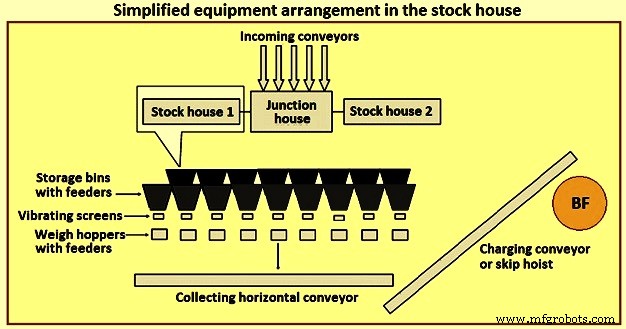
Gbr 4 Penyederhanaan pengaturan peralatan di gudang penyimpanan
Sebelumnya, tipe stock house yang paling umum adalah tipe highline. Rumah stok jenis ini terletak berbatasan langsung dengan tungku. Kereta rel atau derek jembatan memberi makan tempat penyimpanan sementara tempat penyimpanan memberi makan langsung ke mobil skala perjalanan. Operator mobil timbangan secara manual mengontrol gerbang pembuangan sampah untuk memasukkan bahan dalam jumlah tertentu ke dalam hopper yang dilengkapi timbangan yang terletak di mobil timbangan. Setelah mengumpulkan jenis dan jumlah material yang tepat, operator memindahkan mobil timbangan ke posisi di atas 'skip pit' dan membuang beban, melalui parasut, ke dalam gerbong yang menunggu. Mobil skip kemudian diangkat ke atas tungku.
Jenis stock house highline, bersama dengan mobil skala, telah menghadirkan beberapa pilihan untuk penyediaan penyaringan muatan besi (bijih, sinter, dan pelet). Karena pengetahuan tentang proses BF telah meningkat, persyaratan yang lebih ketat untuk beban telah dikembangkan. Konsep 'beban yang direkayasa' diakui dengan baik saat ini di industri. Hal ini biasanya diterima bahwa ada batasan untuk fleksibilitas dan kemampuan beradaptasi dari highline stock house untuk mendukung persyaratan ini. Oleh karena itu, gudang penyimpanan tipe highline telah digantikan oleh gudang penyimpanan dengan konveyor otomatis untuk memasok bahan pengisi ke BF.
Rumah stok otomatis biasanya terdiri dari dua jenis yang berbeda dan berbeda. Tipe pertama adalah penggantian mobil timbangan di bawah tempat bahan baku dengan sistem pengumpan dan ban berjalan. Konveyor terpisah disediakan untuk setiap jenis bahan baku (kokas, bahan bantalan besi, dan bahan fluks dan aditif, dll.) di mana deretan tempat penyimpanan dipasang, dengan pengumpan bergetar untuk melepaskan bahan beban dari tempat penyimpanan ke konveyor. Untuk bahan bantalan kokas dan besi, layar getar terletak di pelepasan setiap konveyor untuk menyaring bahan dan memasukkan bahan yang disaring ke dalam gerbong penimbangan. Jenis sistem ini terus memberi makan gerbong timbang di depan gerbong.
Tipe kedua dari gudang penyimpanan otomatis adalah struktur besar tempat penyimpanan yang dibangun seluruhnya di atas tanah dan cukup jauh dari BF. Ini biasanya dilakukan untuk BF di mana konveyor sabuk digunakan untuk membawa material beban ke bagian atas tungku, bukan mobil lompat. Metode pengisian tempat penyimpanan biasanya dengan sistem ban berjalan. Bahan baku diambil dari tempat penyimpanan dengan vibrating feeder dan belt conveyor ke dalam hopper penimbangan. Hopper timbangan pada gilirannya melepaskan material ke konveyor utama melalui konveyor pengumpul. Hopper penimbangan diprogram untuk menimbang bahan mentah dalam urutan yang benar ke sabuk konveyor utama ke bagian atas tungku.
Penyediaan gudang penyimpanan otomatis dapat menyediakan umpan bahan baku yang lebih efisien ke gudang penyimpanan dan pemilihan, penyaringan, penimbangan, dan pengiriman beban yang lebih efisien ke tungku. Rumah tumpukan otomatis dapat ditempatkan secara langsung bersebelahan dengan gerbong pengumpanan tungku, atau dapat ditempatkan jauh dari tungku untuk pengisian melalui ban berjalan.
Otomatisasi gudang penyimpanan telah meningkatkan kemampuan produksi secara signifikan, meningkatkan efisiensi operasi, dan menghilangkan varians operasi yang disebabkan oleh operator dan peralatan. Namun, dalam praktiknya, gudang penyimpanan otomatis yang modern bisa sangat kompleks. Gudang itu sendiri dapat diberi makan oleh konveyor, yang pada gilirannya dibuang ke konveyor yang tersandung untuk mendistribusikan bahan ke berbagai tempat sampah. Tata letak konveyor dan peralatan di gudang penyimpanan dapat diatur dalam banyak cara. Penempatan stock house yang berdekatan dengan tungku sering mengakibatkan kemacetan tata letak dan membatasi fleksibilitas untuk modifikasi di masa mendatang.
Sistem pengangkatan
Material beban biasanya diangkat ke bagian atas BF dengan bantuan mobil loncatan atau dengan ban berjalan.
Lewati pengangkatan mobil – Penggunaan skip car untuk BF berkembang dari industri pertambangan. Mobil skip BF berukuran sesuai dengan throughput tungku. Jelas, beberapa faktor seperti kapasitas kerekan, desain jembatan layang, dan sebagainya, memiliki pengaruh atau kendalanya sendiri pada ukuran lompatan.
Biasanya, dua lompatan beroperasi dengan cara yang berlawanan (untuk mengurangi daya angkat yang dibutuhkan) pada kerekan umum. Loncat berjalan pada rel pada jembatan lompat, biasanya dipasang pada kemiringan sekitar 60 derajat hingga 80 derajat dari horizontal. Lompatan penuh berakselerasi perlahan saat meninggalkan lubang lompat, berakselerasi secepat mungkin mencapai dan melaju dengan kecepatan maksimum untuk sebagian besar gaya angkat. Kerekan memperlambat lompatan saat mendekati bagian atas jembatan lompatan. Roda loncatan dipandu oleh rel dumping dan klakson saat loncatan dibalik ke peralatan pengisian atas tungku. Saat loncatan pengangkat mencapai dan berhenti pada posisi pembuangan akhir, loncatan kosong (turun dengan kecepatan yang sama) baru saja mencapai dasar perjalanannya ke dalam lubang loncatan, menunggu pengisian. Sistem skip charging adalah teknik yang andal dan efektif untuk mengirimkan beban ke bagian atas tungku. Namun, hal ini kurang fleksibel bagi operator karena loncatan hanya dapat menampung sejumlah material tertentu (pembebanan berlebih mengakibatkan penimbunan yang berlebihan atau beban kerekan yang berlebihan) atau menjadi tidak efisien jika diperlukan volume beban spesifik yang kecil. Gambar 5 menunjukkan skema skip car hoisting.
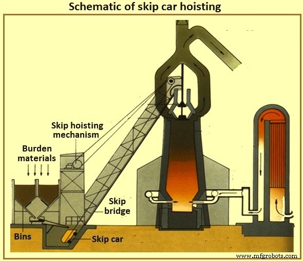
Gbr 5 Skema pengangkatan mobil lewati
Konveyor pengisian tungku – Dengan konveyorisasi gudang stok, konveyorisasi sistem pengangkat telah tiba. Saat ini, gudang penyimpanan biasanya terletak jauh dari tungku dan satu sabuk konveyor besar membawa beban ke bagian atas tungku. Jika bagian atas tungku sekitar 60 meter, kemudian sabuk konveyor dipasang pada kemiringan 8 derajat ke posisi horizontal, gudang penyimpanan harus ditempatkan setidaknya 427 meter dari tungku. Kemiringan sabuk yang lebih curam biasanya dihindari untuk meminimalkan roll back material. Adalah normal untuk mengisi bahan-bahan lain secara langsung di atas dan setelah akhir pengisian besi pada ban berjalan untuk menahan bahan besi di tempatnya sampai mereka mencapai bagian atas tungku.
Sistem pengisian daya di bagian atas tungku
Tungku yang tepat dioperasikan dengan tekanan atas positif tinggi. Gas BF yang sebagian terdiri dari karbon monoksida, karbon dioksida, dan nitrogen dihasilkan oleh proses BF bersama dengan sejumlah besar debu yang terperangkap. Operator BF harus mempertahankan tekanan atas karena manfaat proses dan untuk menahan gas dan debu (baik untuk nilai bahan bakar dan tujuan pengendalian lingkungan). Namun, operator harus secara teratur menempatkan material beban di dalam bagian atas tungku untuk mengisi kembali proses internal, tanpa kehilangan tekanan bagian atas tungku.
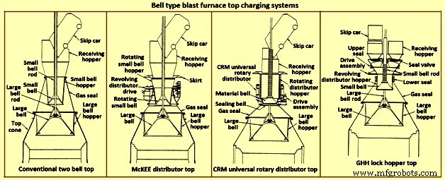
Jenis lonceng atas – Selama beberapa tahun, jenis tungku atas yang paling umum adalah tungku dua lonceng (Gbr 6). Saat beban mencapai bagian atas tungku (dengan melewati atau dengan konveyor), beban tersebut jatuh ke dalam hopper penerima dan ke dalam hopper lonceng kecil. Lonceng kecil (pengecoran baja berbentuk kerucut dengan diameter sekitar 2,6 meter dan tinggi 1,4 meter untuk BF 5.000 tHM per hari) menurunkan dan memungkinkan beban jatuh ke hopper lonceng besar. Lonceng kecil diangkat dan disegel pada kursi tetap pada hopper bel kecil. Tergantung pada volume hopper bel besar, beban tambahan diurutkan ke hopper bel besar oleh bel kecil. Selama proses ini, bel besar tetap tertutup, menyegel tungku. Ketika jumlah beban yang benar telah dikumpulkan, lonceng besar (pengecoran baja berbentuk kerucut dengan diameter sekitar 5,5 meter dan tinggi sekitar 3,5 meter untuk BF 5.000 tHM per hari) diturunkan dan memungkinkan beban meluncur ke bawah lonceng ke dalam bagian atas tungku yang tepat. Setelah beban dilepaskan, bel besar diangkat dan disegel di bagian bawah gerbong bel besar. Gambar 6 menunjukkan sistem pengisian atas BF tipe lonceng.
Gbr 6 Sistem pengisian atas tanur sembur tipe lonceng
Jelas, kontrol distribusi beban dengan tungku untuk jenis bagian atas dibatasi oleh seberapa merata beban ditempatkan pada bel besar (skip dumping mengakibatkan penempatan beban yang tidak merata ke bagian atas jenis ini) dan kurva jatuh dari bagian atas. bahan beban tertentu (yaitu beban kokas atau besi) saat mereka meluncur dan jatuh dari bel besar. Selanjutnya, dua bagian atas lonceng rentan terhadap hilangnya penyegelan lonceng besar dan kecil dan pengepakan antara batang lonceng besar dan tabung lonceng kecil. Kebocoran bel dihasilkan dari abrasi oleh material beban yang meluncur di atas permukaan penyegelan bel. Kebocoran rod packing adalah akibat dari abrasi dari butiran halus baik dari dalam tungku atau dari pengumpulan pada bell rod besar setelah beban dibuang ke hopper penerima.
Dalam upaya untuk meminimalkan keausan permukaan penyegelan bel yang besar, gas BF yang diambil dari dalam tungku dimasukkan di antara bel untuk menyamakan ruang (mengurangi perbedaan tekanan di seluruh permukaan penyegelan bel yang besar). Gas ini dilepaskan ke atmosfer sebelum membuka bel kecil untuk memungkinkan masuknya lebih banyak beban. Beberapa opsi yang tersedia untuk meningkatkan batasan sistem atas dua tipe lonceng diberikan di bawah ini.
Distributor McKEE – Distributor McKEE (Gbr 6) selama beberapa tahun adalah peningkatan distribusi beban utama yang tersedia untuk tipe dua bel atas. Namun, dengan cepat digantikan oleh teknologi lain. Desainnya menggabungkan kemampuan untuk memutar bel kecil dan hopper bel kecil bersama-sama saat mobil lompat sedang digunakan. Beban didistribusikan secara merata ke hopper bel kecil, sehingga meningkatkan penempatan beban yang merata ke bel besar. Jenis atasan ini rentan terhadap keausan lonceng kecil dan besar dan selanjutnya kehilangan efek penyegelan.
Atas distributor putar universal CRM – Distributor putar universal CRM (Centre Recherches Metallurgiques – Belgia) (Gbr 6) dikembangkan untuk menghilangkan hilangnya efek penyegelan bel kecil. Dua bel (bel penyegel dan bel material) dipasang di tempat bel kecil biasa. Hopper beban berputar dipasang pada bel material. Lonceng penyegel terletak di bawah bel material dan disegel pada kursi tetap. Selama pelepasan loncatan, hopper beban dan bel material penutup diputar untuk mengisi hopper secara merata. Saat pengisian selesai, putaran hopper berhenti. Saat tiba waktunya untuk membuang ke bel besar, hopper berputar, bel material, dan bel penyegelan diturunkan. Lonceng penyegel diturunkan di bawah tempat duduk tetap. Di tengah proses penurunan, penurunan hopper dihentikan dan bel material serta bel penyegel terus turun hingga mencapai posisi berhenti. Saat celah terbuka antara bel material dan hopper, beban dilepaskan secara merata ke hopper bel besar. Saat beban meninggalkan celah, beban tidak bersentuhan dengan permukaan dudukan katup penyegel, sehingga mempertahankan kemampuan penyegelan atas. Gaya atas ini mampu mempertahankan tekanan internal 0,2 MPa.
Bagian atas CRM meningkatkan kemampuan penyegelan dan umur panjang dari dua bagian atas lonceng. Namun, ini tidak memberikan peningkatan distribusi beban tungku yang dramatis di atas distributor McKEE dan tidak menghilangkan kerentanan permukaan penyegelan bel yang besar.
Atas hopper kunci GHH – Bagian atas hopper pengunci GHH (Gbr 6) adalah modifikasi dari bagian atas dua lonceng. Ini mengurangi ketergantungan pada bel besar untuk mempertahankan segel gas. Penambahan hopper kunci dengan katup segel terpisah untuk setiap lokasi pembuangan loncatan memberikan kapasitas tambahan untuk menyegel bagian atas. Bel besar dapat dioperasikan tanpa tekanan diferensial di seluruh permukaan penyegelannya (yaitu, tekanan atas tungku sama dengan tekanan hopper lonceng besar). Operasi diberikan di bawah ini.
Sebuah lompatan membuang beban beban ke dalam hopper kunci melalui hopper penerima dan katup segel terbuka. Beban ditempatkan pada bel kecil yang berputar dan secara merata mengisi hopper distributor yang berputar di atas bel kecil. Segel antara hopper kunci dan hopper bel kecil yang berputar terbuka saat rotasi sedang berlangsung. Ketika pelepasan beban dari lompatan selesai, katup segel dan segel antara hopper kunci dan hopper bel kecil ditutup. Gas pemerataan diperkenalkan dan hopper kunci diberi tekanan ke tekanan atas tungku. Bel kecil kemudian diturunkan untuk memasukkan beban ke dalam gerbong bel besar. Bel kecil menutup dan tekanan dari hopper kunci dilepaskan ke atmosfer. Katup segel di sisi yang berlawanan (yaitu di posisi pembuangan lewati lainnya) dibuka. Segel antara hopper kunci dan hopper bel kecil dibuka. Rotasi bel kecil dan hopper dimulai. Bagian atas sekarang dapat menerima beban dari lompatan lainnya.
Jenis atas ini meningkatkan kemampuan penyegelan dan umur panjang dari dua bagian atas lonceng. Namun, bagian atas hopper kunci tidak memberikan peningkatan distribusi beban tungku yang dramatis baik di bagian atas McKEE atau CRM. Meskipun bel besar tidak lagi diperlukan untuk melakukan fungsi penyegelan, umur panjang efek penyegelan bel kecil masih penting.
Armor bergerak – Langkah utama yang diambil untuk meningkatkan distribusi beban dari tipe bell top adalah pengembangan movable armor (Gbr 7). Deflektor yang dapat disesuaikan dipasang di area tenggorokan tungku untuk membelokkan beban setelah meluncur dari bel besar. Armor bergerak disesuaikan tergantung pada bahan beban spesifik yang dikeluarkan dan di mana operator ingin menempatkan beban di dalam tungku.
Beberapa produsen menyediakan berbagai jenis baju besi bergerak. Segmen baju besi individu dapat dipindahkan secara seragam (bersamaan dan merata) di dalam tungku untuk menempatkan beban dalam pola annular. Jenis lain dari armor bergerak tersedia untuk memberikan kontrol individu dari pelat armor untuk mencapai pola distribusi non-sirkular.
Beberapa kelemahan yang terkait dengan pelindung bergerak adalah (i) sebagian besar komponen mekanis dan aus terletak pada lingkungan yang keras dari kerucut atas tungku, (ii) beberapa kehilangan volume kerja internal diperlukan untuk memberikan jarak bebas antara pelindung bergerak dan stockline desain. level (walaupun area tungku ini tidak dapat diklasifikasikan sebagai zona produktivitas kasar untuk pertimbangan volume kerja tungku, dan (iii) kemampuan terbatas untuk membelokkan beban ke bagian tengah tungku, terutama ketika level stockline sudah tinggi. karakteristik pelet sering kali meniadakan perpindahan terbatas dari baju besi bergerak.
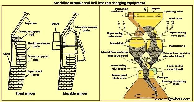
Fig 7 Stockline armor dan bell less top charging equipment
Sistem pengisian daya tanpa lonceng – Pada awal 1970-an, Paul Wurth S.A. dari Luksemburg mengembangkan sistem pengisian bell less top (BLT) (Gbr 7). Jenis bagian atas tungku ini merupakan penyimpangan radikal dari bagian atas jenis lonceng. Beban dapat ditempatkan di dalam tungku dalam pola apa pun yang dibutuhkan oleh operator tungku. Cincin annular, spiral, segmen, dan penempatan titik adalah pola umum yang dapat dicapai dengan memiringkan dan memutar secara sinkron atau independen dari saluran distribusi beban yang terletak dengan kerucut atas tungku.
Penyegelan atas tungku dipertahankan selama kampanye tungku. Kegiatan pemeliharaan sederhana dan durasi pendek. Biasanya, BLT terdiri dari saluran penerima atau hopper (menerima beban dari lompatan atau dari ban berjalan), hopper kunci dengan katup segel atas dan bawah, gerbang kontrol aliran material, gearbox penggerak saluran utama (air atau gas -unit berpendingin yang digunakan untuk rotasi dan kemiringan saluran), dan saluran distribusi beban. Ada tiga jenis utama BLT yaitu (i) hopper paralel, (ii) feed sentral, dan (iii) tipe kompak.
Biasanya, tipe paralel menggabungkan dua hopper kunci (hopper telah dipasang pada beberapa tungku untuk tujuan throughput dan cadangan; satu tipe hopper 'eksentrik' telah dipasang untuk aplikasi dengan izin terbatas). Sejak awal 1980-an, beberapa BF telah memilih tipe hopper kunci tunggal 'pengumpanan sentral' untuk perbaikannya dalam pemisahan beban dan kontrol distribusi beban yang menghasilkan operasi tungku yang lebih baik.
Jenis atas BLT 'kompak' telah dikembangkan untuk tungku kecil hingga menengah untuk memungkinkan pengenalan BLT (dan kelebihannya) ke tungku di mana jenis BLT yang lebih besar lainnya tidak dapat digunakan karena kendala biaya atau fisik. Langkah-langkah dalam pengoperasian BLT untuk tipe umpan sentral adalah (i) beban dikeluarkan dari skip atau ban berjalan melalui saluran penerima atau hopper melewati katup segel terbuka ke dalam lock hopper, (ii) setelah beban diterima di kunci. hopper, katup segel atas ditutup dan gas penyeimbang dimasukkan untuk menekan hopper kunci ke tekanan tungku, (iii) katup segel bawah terbuka, (iv) beban dilepaskan dari hopper kunci karena gerbang material telah diatur ke bukaan yang dipilih sebelumnya untuk menyesuaikan dengan bahan beban spesifik yang akan dibuang, (v) beban turun secara vertikal melalui cerat pengumpan dengan kotak roda gigi transmisi utama dan jatuh ke saluran distribusi beban, (vi) saluran distribusi beban mengarahkan beban ke yang diperlukan point(s) within the furnace, (vii) when the lock hopper is fully discharged (monitored by load cells and / or acoustic monitoring), the lower seal valve is closed, (viii) a relief valve is opened to exhaust the lock hopper to atmosphe re (or through an energy recovery unit), and (ix) the upper seal valve opens and the sequence is repeated.
The advantages of BLT over other top charging systems include higher top pressure capability (i.e. 0.25 MPa), fuel savings, increased production, more stable operation, reduced maintenance in terms of cost and time, increased furnace campaign life, and improved furnace operational control when employing high coal injection rates at the tuyeres.
Gimbal system of charging – The purpose of the Gimbal system of charging is to facilitate controlled distribution of charge material into the BF via a Gimbal type oscillating chute through a holding hopper and variable material gate opening such that the pressurized charging system above can operate independently of the distribution system. It utilizes a conical distribution chute, supported by rings in a Gimbal arrangement, producing independent and combined tilting of the chute axis. The Gimbal distributor, as part of the overall BF top charging system, offers a fully integrated charging solution, generating considerable improvement in BF operation and maintenance cost. The Gimbal system utilizes a conical distribution chute, supported by rings in a Gimbal arrangement, producing independent, and combined tilting of the chute axis.
The Gimbal top incorporates a full complimentary range of furnace top distribution equipment including distribution rockers, upper seal valves, hoppers, lower seal valves, material flow gates and goggle valve assemblies, all discharging through hydraulically driven distribution chutes. The tilting chute is driven by two hydraulic cylinders, mounted 90 degree apart. This type of suspension and drive arrangement results not in a rotation of the tilting chute, but in a circular path by superposition of both tilting motions. Independent or combined operation of the cylinders allows the chute axis to be directed to any angle, or even along any path. Motion is supplied by two hydraulic cylinders, each operating through a shaft, connecting rod, and universal joint in order to drive the Gimbal rings. Through the movement of the hydraulic cylinders, the distribution chute allows precise material distribution with potential for an infinite number of charging patterns at varying speeds. These include ring, spiral, centre, spot, segment or sector charging, providing complete control of material charging into the furnace.
The whole distributor assembly is enclosed in a gas tight housing, which is mounted directly onto the top flange of the BF top cone. The housing contains a fixed inlet chute and a tilting distribution chute supported by rings in a Gimbal arrangement allowing independent and combined tilting of the chute axis. The assembly is made from a combination of stainless and carbon steel material with the fixed inlet chute and tilting chute body lined with ceramic material to give superior wear protection. A closed-circuit water cooling system supplies cooling water through the main shafts, Gimbal bearings, and universal joint bearings in order to cool the moving elements of the Gimbal distribution system.
The key features of the Gimbal design are (i) simple, rugged design, using levers driven by the hydraulic cylinders, (ii) drive cylinders are mounted outside pressure envelope, hence not subject to hot and dusty service conditions, (iii) Gimbal ring arrangement gives simple tilting motion in two planes, which when superimposed gives 360 degrees distribution, and (iv) wear on the tilting chute is equalized around its circumference giving a long extended operational life.
The BF Gimbal top is an automated, computer-controlled pressurized charging system designed to (i) receive charges of ore, coke, and miscellaneous materials in the holding hopper, independently of the distribution system below, (ii) release those discharges, as needed, to a dynamic distribution chute located below the holding hopper, and (iii) distribute material in prescribed patterns to the furnace stock-line in accordance with a predetermined charging matrix. Control of the Gimbal distribution chute is fully integrated into the overall furnace charging software. The system provides a high level of accuracy and control for the Gimbal movements and hence the positioning of the distribution chute. Gimbal material distributor is shown in Fig 8.
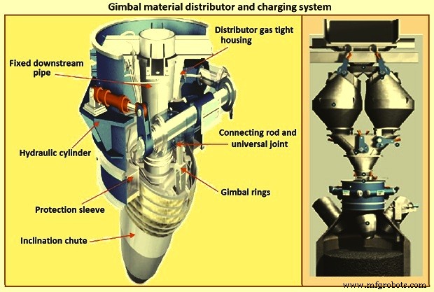
Fig 8 Gimbal material distributor and charging system
Furnace proper
The furnace proper is the main reactor vessel of the BF ironmaking process. Its internal lines are designed to support the internal process. Its external lines are designed to provide the necessary systems to contain, maintain, monitor, support, and adjust the internal process.
The BF process is a counter flow process. The process comprises of (i) burden at ambient conditions is placed in the furnace top onto the column of burden within the furnace, (ii) as the burden descends with the burden column, it is heated, chemically modified, and finally melted, (iii) further chemical modifications occur with the molten material, (iv) the molten products are extracted near the bottom, (v) melting of the burden material and extraction result in the descent of the burden column and the need for replenishment of the burden at the top, (vi) hot blast air is introduced through tuyeres near the bottom, (vii) BF gases are generated in front of the tuyeres and ascend through the burden and chemically modify the descending burden as well as themselves get chemically modified and cooled, (viii) BF gas (and dust) is extracted near the top of the furnace, and (ix) heat is extracted from the vessel in all directions (primarily through the lining cooling system) and along with the BF gas, liquid iron and liquid slag. Fig 9 shows cross section and types of BF.
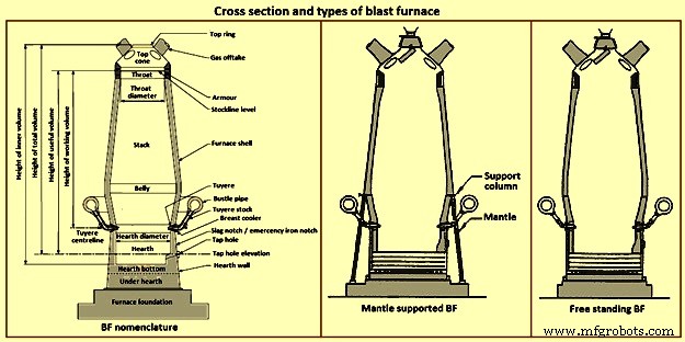
Fig 9 Cross section and types of blast furnace
Furnace type – Furnaces are constructed to be mantle supported or free standing. Mantle supported BFs characteristically have a ring girder (mantle) located at the bottom of the lower stack of the furnace. The mantle is supported in turn by columns which are on the main furnace foundation. The hearth, tuyere breast, and bosh are also supported by the foundation. Furnaces with mantle support column tend to have restricted access and reduced flexibility for improvements in the mantle, bosh, and tuyere breast areas.
Since thermal expansion is a major consideration in furnace shell design, the mantle style of furnace provides an interesting design consideration. The mantle support columns are relatively cool. The mantle tends to maintain a constant height, throughout the furnace campaign with respect to the furnace foundation. Thermal expansion of the stack due to process heat is considered to be based at the ‘fixed’ mantle (i.e. the top of the furnace raises with respect to the mantle). The effective height of the bosh, tuyere breast, and hearth wall shells (supported on the furnace foundation) increases due to the thermal expansion of the shell caused by the process heat. The lower portion of the furnace lifts upwards towards the fixed mantle. Hence, the provision of an expansion joint of some type is needed at the bosh / mantle connection or somewhere appropriately located in the lower portion of the furnace.
Free standing furnaces have been developed to eliminate the column and permit the installation of major equipment and furnace cooling improvements. This furnace type has a thicker shell for structural support. Installation and maintenance of a reliable cooling and lining system is necessary in order to sustain the structural longevity of the shell.
Two variations of the free standing furnace have been used. One type provides for a separate structural support tower to carry the furnace off-gas system and charging / hoisting system load. The other type (while it does employ a separate support tower for shell replacement purposes during relines) uses the furnace proper to support the off-gas system and charging / hoisting system loads. Special consideration to the furnace shell design is to be made regardless of the furnace type. The furnace vessel is subjected to internal pressures from the blast and gas, burden, liquid iron and slag. Dead and live load during all operating, maintenance, and reline stages are to be considered as well.
Furnace zones – The major zones of the furnace proper are (i) top cone, (ii) throat, (iii) stack, (iv) mantle / belly, (v) bosh, (vi) tuyere breast, (vii) hearth walls, (viii) hearth bottom, (ix) foundation.
Top cone – The top cone or dome is the uppermost part of the furnace proper. It supports the furnace top charging equipment, and the BF top gas collection system. Stock rods (stockline recorders or gauges) are normally placed here to monitor the upper level of the burden in the furnace. These devices are the units which provide the permissive or indication signals to charge the next scheduled burden input to the furnace. Typically, they are weights lowered by special winches, or microwave units. Some furnaces incorporate radio-active isotope emitters and detectors mounted in the furnace throat to monitor the burden level. Infrared camera can be installed in the top cone to monitor the BF top gas temperature distribution as it escapes the furnace burden stockline.
The top cone is the coolest zone of the furnace proper but can be exposed to extremely high temperatures if burden ‘slips’ (rapid, uncontrolled burden descent after a period of unusual lack of descent). The newly charged burden falls through this zone and the BF top gas is carried away from this section.
Throat – Steel wear plates or armour are installed in this zone. Here, abrasion of the furnace lining from the charged burden is the prime cause of deterioration. Furnace operators work to maintain the upper level of the burden (the stockline) in this region. Movable armour can be installed in this area in order to deflect the burden falling from a large bell. With the installation of the BLT, wear of the stockline area can be greatly reduced. Some BF users select to eliminate the armour plates and use an abrasion resistant refractory lining instead.
Stack – The stack (sometimes called shaft or the ‘in-wall’) is the zone between the mantle or belly on a free standing furnace and the stockline area. Smooth, uniform lines (the process ‘working surface’) of the stack are essential for uniform and predictable burden descent, BF gas ascent, and stable process control throughout the furnace campaign. Process considerations dictate a larger diameter at the base of the stack than at the top. Typical stack angles are in the range of around 85 degrees from the horizontal.
Mantle / belly – The mantle or belly area provides the transition between the expanded stack and bosh sections. Maintenance of the effectiveness of the cooling / lining system is particularly important for the mantle type furnace in order to protect the mantle structure. Thermal protection is important for the free standing furnace type as well. However, the free standing design is less complicated and more accessible in this area.
Bosh – The bosh area lies between the tuyere breast and the mantle / belly of the furnace. The bosh diameter increases from bottom to top. The inclination of the bosh permits the efficient ascent of the process gases and has been found to be necessary in order to provide the needed zone service life (the process gases are extremely hot and internal chemical attack conditions are severe). Typical bosh angles are in the range of around 80 degrees from the horizontal. Boshes are of two basic types, namely (i) banded and (ii) sealed. They can be cooled by different techniques.
Banded boshes are found in older mantle supported furnaces (they cannot be applied to free standing furnaces). A number of steel bands are placed in incrementally increasing diameters (smallest at the bottom of the bosh and largest at the top) and are tied together with connecting strips. Gap between the bands permits the introduction of copper cooling plates. Ceramic brick lining is to be used as air infiltration results in oxidation of carbon based linings. Gas leakage through the banded bosh can be high. This type is not suitable for BFs with high blast pressure / high top pressure. Banded boshes provide adequate flexibility to eliminate the requirement for a shell expansion joint in the lower portion of the furnace.
Sealed boshes, using continuous steel shell plate instead of separate bands, are employed to permit the use of improved cooling / lining systems, higher furnace operating pressures, and the free standing furnace type. Sealed boshes retain valuable gases with the furnace, hence improving the metallurgical process. As well, the seal bosh, since it precludes air entry into the lining, supports the use of carbon based refractories.
Tuyere breast – Hot blast air is introduced to the furnace through tuyeres (water-cooled copper units) located within the tuyere breast. The number of tuyeres needed depends upon the size (production capacity) of the furnace. The tuyere breast diameter, tuyere spacing, and number of tuyeres are influenced by the expected raceway zone size in front of each tuyere.
Tuyere stocks (Fig 10) convey the hot blast air from the bustle pipe to the tuyeres. The tuyeres are supported by tuyere coolers (water-cooled copper units) which are in turn supported by steel tuyere cooler holders (either welded or bolted to the furnace shell). Special consideration are to be made in the tuyere breast shell and lining design in order to maintain effective sealing of the different components in order to prevent escape and loss of the furnace gases.
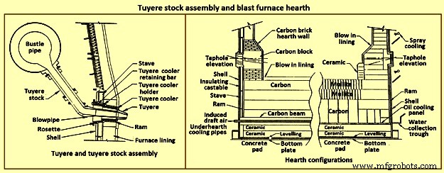
Fig 10 Tuyere stock assembly and blast furnace hearth
Hearth – The hearth (Fig 10) is the crucible of the furnace. Here, hot metal and liquid slag are collected and held until the furnace is tapped. The hearth wall is penetrated by tap holes (frequently called iron notches) for the removal of the collected hot metal and liquid slag. The number of tap holes is dependent upon the size of the furnace, hot metal, and liquid slag handling requirements, physical and capital constraints etc.
Several furnaces are equipped with a slag or cinder notch (normally one per furnace, although some furnaces can have two). The slag notch opening elevation is normally sufficiently higher than the iron notch elevation. In earlier days, when slag volumes were high, the slag was flushed from the slag notch periodically. This simplified the iron / slag separation process in the cast house. More commonly now, however, the slag notch is retained solely for initial furnace set-up procedures or for emergency use in case of iron notch or other furnace operating problems.
Hearth bottom – The hearth bottom supports the hearth walls and is flooded by the iron within the furnace. As the campaign progresses, the hearth bottom lining wears away to a fixed equilibrium point. The remaining refractory contains the process and with sufficient cooling or inherent insulation value protects the furnace pad and foundation.
Cooling system
The application of specific cooling techniques to individual furnace zones is dependent upon several factors such as campaign life expectancy, furnace operational philosophy, burden types, refractories, cost constraints, physical constraints, available cooling media, and preferences etc. Different cooling techniques can be provided for different zones to assist the lining to resist the specific zone deterioration factors. Normally, the provision of adequate cooling capacity is necessary in each of the applicable furnace zones if the lining system located there is to survive. Where the thermal, chemical, and to some extent the abrasive conditions of the process are extreme, sufficient cooling is to be provided to maintain the necessary uniform interior lines of the furnace and to protect the furnace shell.
Typically, the top cone and throat areas of the furnace are not cooled. The hearth bottom can be ‘actively’ cooled by under hearth cooling (air, water, or oil media) or ‘passively’ cooled by heat conduction though the hearth bottom lining to the hearth wall. The basic cooling options for the balance of the furnace are (i) no cooling (typically the upper portion of the stack is not cooled in several furnaces, (ii) shower or spray cooling, (iii) jacket or channel cooling, (iv) plate cooling, and (v) stave cooling.
Shower or spray cooling – Water is directed by sprays or by overflow troughs and descends in a film over the shell plate. Effective spray nozzle design, numbers and positioning are important for proper coverage and to minimize rebound. Proper deflector plate design is necessary to ensure efficient cooling water distribution and to minimize splashing. Shower cooling is frequently employed in the bosh and hearth wall areas. Spray cooling is normally applied for emergency or back-up cooling, primarily in the stack area. Exterior shell plate corrosion and organic fouling are common problems which can disrupt water flow or insulate the shell from the cooling effect of the surface applied cooling. Water treatment is an important consideration to retain effective cooling.
Jacket or channel cooling – Fabricated cooling chambers or indeed structural steel channels or angles are welded directly to the outside of the shell plate. Water flows at low velocity though the cooling elements in order to cool the shell and the lining. Jacket or channel cooling is frequently applied to the hearth walls, tuyere breast, and bosh areas. Scale build-up on the furnace shell and debris collection in the bottoms of the external cooling elements can compromise the cooling effectiveness. Hence periodic cleaning of the cooling elements is necessary.
The critical area of concern in the cooling schemes mentioned so far is the necessity for the shell plate to act as a cooling element. If extreme heat loads are acting upon the inside face of the shell, then there exist an extremely high thermal gradient across the shell. This effect results in high thermally induced shell stresses and eventual cracking. The cracks start from the inside of the furnace and propagate to the outside. The cracks remain invisible (other than a ‘hot spot’) until they fully penetrate the shell plate. Through cracking of the shell plate results in the leak of the BF gas, exposed shell carburization, and disruption of the cooling effect (particularly spray or shower cooling). Shell cracking into a sealed cooling jacket or channel is difficult to locate and can result in long furnace outage time for repair. Entry of water into the furnace (frequently when the furnace is off-line and internal furnace gas pressure cannot prevent entry of cooling water though shell cracks) can have detrimental effect upon the furnace lining. Water in the furnace can be potentially dangerous due to explosion risk (steam or hydrogen). Since shower and jacket cooling rely on the shell plate to conduct the process heat to the cooling media, the plate and stave cooling are configured to isolate the shell from process.
Plate and cigar cooling – Installation of cooling elements though the shell of the furnace (Fig 11) has been a major furnace design improvement resulting in effective cooling of the furnace lining and protection of the shell plate. Cooling is provided along the length of the cooling element penetration into the lining. The inserted elements provide positive mechanical support for the refractory lining. Typical cooling plate manufacture is cast high conductivity copper. Single or multiple passes of cooling water can be incorporated. Cooling boxes with larger vertical section have been produced from cast steel, iron, or copper.
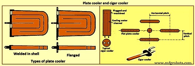
Fig 11 Plate cooler and cigar cooler
Cigar type (cylindrical) coolers (Fig 11) of steel and /or copper have also been successfully used. The philosophy of dense plate cooling (i.e. vertical pitch of 350 mm to 400 mm centre-to- centre, and horizontal pitch of 600 mm (centre-to-centre) has improved the cooling effect and increased lining life.
Copper cooling plates have traditionally been anchored in the shell plate with retainer bars or bolted connections to permit ready replacement if plate leakage occurs. More recently, plates have been designed with steel sections at the rear of the plate for welding directly to the steel shell. While sometimes taking longer to replace, this type provides a positive seal against BF gas leakage. Plate coolers are typically installed in areas above where the liquid iron collects in the furnace. Hence the mid-point of the tuyere breast, right up to the underside of the throat armour is the range of application.
Stave cooling – Cast iron cooling elements (Shannon plates or staves) have been used for several years in the bosh and hearth wall areas. These castings have cored cooling passages of large cross-section. While their service life have been not remarkable in the bosh, multiple campaigns have been normal for the hearth wall. These staves frequently suffered from low flow rates of marginal quality cooling water (scaling and debris deposition / build-up) and sometimes casting porosity. Water leaks into the hearth wall can be a considerable problem.
In the 1950s, the then USSR developed a new type of stave cooler (Fig 12) and ‘natural evaporative stave cooling’. For this design, castings were of gray cast iron containing steel pipes for water passes. The pipes were coated prior to casting to prevent carburization of the cooling pipe and metallurgical contact with the stave body material. The staves were installed in horizontal rows with the furnace and the cooling pipes projected through the shell. Vertical column of staves were formed by the inter-connection of the projecting pipes from one stave up to the corresponding stave in the next row. Staves can be applied to all the walls in the zones below the armour. Staves in the hearth wall and tuyere breast are supplied with smooth faces. Staves in the bosh, mantle / belly and stack normally have rib recesses for the installation of refractory.
Evolution of the stave cooler design has been dramatic. Staves in the higher heat load areas are now typically cast from ductile iron for improved thermal conductivity and crack resistance. While early stave design used castable refractory (installed after stave installation within the furnace), ribs now normally incorporate refractory bricks, either cast in place (with the stave body at the foundry) or slid and mortared in place prior to installation in the furnace. Fig 12 shows stave cooler and generations of stave development.
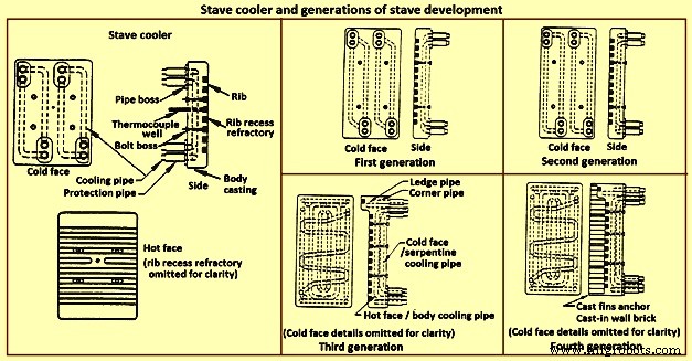
Fig 12 Stave cooler and generations of stave development
Staves are normally expected to retain a refractory lining in front for some time. After loss (expected) of the lining the staves are designed to resist the abrasive effects of descending burden and ascending dirty gas. As well, they are to absorb the expected process heat load and resist thermal load cycling and shock. Four generations of staves (Fig 12) are normally recognized in the industry.
First generation staves are no longer normally used. These staves have four cooling body circuits (with long radius bends which do not effectively cool the stave comers. These staves are made of gray iron castings with castable rib refractory. Second generation staves have four cooling body circuits with short radius bends for improved comer cooling. These staves are made of ductile iron castings with cast-in or glued-in rib bricks. Third generation staves have two-layer body cooling incorporating four or six cooling body circuits (stave hot face) and one or two serpentine cold face circuits (stave cold face) for additional or back-up cooling in the event of hot face circuit loss. These staves have additional edge cooling (top and bottom). The more frequent use of these staves is as cooled ledges to support a refractory lining. These staves have cast-in or mortared-in rib bricks. Fourth generation staves have two-layer cooling (similar to third generation). These staves have cooled ledges and cast-in wall brick lining eliminating the need for a manually placed interior brick lining.
Staves incorporating hot face ledges are more effective in retaining a brick lining than the smoother rib faced bricks. However, once the brick lining disappears, the ledges are very exposed within the furnace. The ledges disrupt burden descent and gas ascent. Exposed ledges tend to fail quickly. They are frequently serviced by cooling water separate from the main stave cooling circuit(s). In this way leaking ledge circuits can be more easily located or isolated. Some stave manufacturers are now providing separate ledge castings so that ledge cracking and loss does not damage the parent staves. As well, there is some present change in philosophy to abandon the application of ledges entirely.
Variations of the basic stave generation types are common. For example, staves of fourth generation type utilizing a refractory castable for the wall ling have been employed successfully. Alternatively, brick linings have been anchored to the stave bodies. Such approaches can be used to substitute for brick support ledges.
A ‘fifth’ generation of staves design has been the developed. It is the copper stave (Fig 13). The development of copper staves was carried out both in Japan and Germany for use in the region of bosh, belly, and lower stack to cope with high heat loads and large fluctuations of temperatures. While Japan has gone for cast copper staves, German copper staves are rolled copper plates having close outer tolerarnces and with drilling done for cooling passages. Drilled and plugged copper staves are typically designed for four water pipes in a straight line at the top and four water pipes in a stright line at the bottom. Materials for internal pipe coils include monel, copper, or steel. Unlike cast iron staves, copper staves are intended to be bonded to the cooling pipe.
The development of the cast-in copper stave has considered the following aspects. As per the first aspect, for the prevention of deformation, appropriate design of the stave length and bolt constrained points is important. The first aspect is that the use of the cast-in steel pipe copper stave with its own design is beneficial for effectively reducing the risk of deformation. Fig 13 shows the constrained points of a rolled copper stave and the cast-in steel pipe copper stave. A rolled copper stave is constrained to the shell by mounting bolts and pins. To prevent the weld at the base of a rising pipe from being damaged by stresses, rising piping is connected to the shell by an expansion joint. Due to this structure, the upper and lower ends of the staves are freely displaced, causing the staves to be easily deformed. The large thermal load which is repeatedly applied to the copper stave in the course of the fluctuation in the BF operations etc., causes plastic strain to be gradually accumulated, and results in large deformation. There are cases in which the deformation at the upper end has reached 50 mm or more and a weld has been broken, under the condition of an overly long stave, an in-appropriate bolt position, or high heat load exceeding the design condition.
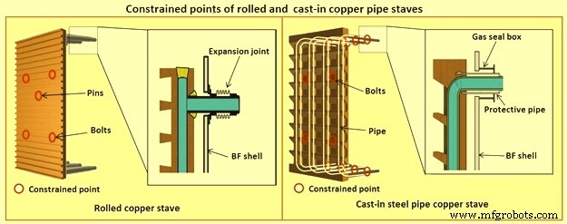
Fig 13 Constrained points of rolled and the cast-in pipe copper stave
Presently, the most popular type of copper stave is the rolled copper stave, the manufacturing process of which involves drilling holes on a copper plate. The water channel ends of these staves are plug-welded. The cast-in steel pipe copper stave, which has been developed, is made by casting bent steel pipes into the copper, a completely different manufacturing process from that of the conventional rolled copper stave. This unique manufacturing method has enabled achieving high energy efficiency and long life of BFs, which cannot be achieved using the rolled copper stave.
Natural evaporative stave cooling (NEVC) is a technique where boiler quality water is introduced into the bottom row of staves and flows by natural mean up the vertical cooling circuits. As the process heat conducts through the stave and cooling pipe into the water, the water in turn heats up. As the water warms, it expands. Since cooler water is being introduced below, the warm water tends to move upwards. At some point in the vertical cooling circuit, the water is at the boiling point. As the water changes its phase to steam, due to the latent heat of vapourization, additional heat is absorbed (driving the phase change). After boiling begins, two-phase flow (water and steam mixture) ascends the cooling pipes to the top of the furnace. Normally located on the furnace top platform are steam separator drums used to extract and vent the steam to atmosphere. Make-up water is introduced to the drum (to replace the discharged steam). The water is piped back by gravity to the furnace bottom and is fed once more to the staves. This cooling technique is very efficient and has low operating costs. There is no pumping equipment. The improvements in this system has been to boost the flow of the cooling water with recirculating pumps (forced evaporative cooling, FEVC) in order to ensure uniform cooling water flow and to cool the recirculating water (forced cold water cooling – FCWC). Both of these approaches have resulted in improved stave and lining life.
Staves provide an excellent protection for the shell plate throughout their service life (which is extended while the interior brick lining remains in place). Stave application has been implemented in all areas of the furnace from hearth wall up to and including the upper stack.
One drawback for conversion of an existing plate cooled furnace to stave cooling can be the cost of a new shell. However, if the existing shell is already in distress and is to be replaced in any event, the conversion cost is not a major factor.
Cast house
The cast house (Fig 14) is the area or areas at the BF where equipment is placed to safely extract the hot metal and liquid slag from the furnace, separate them, and direct them to the appropriate handling equipment or facilities. The hot metal and liquid slag are removed from the furnace through the tap hole. Only infrequently today slag is flushed from the slag notch. The equipment for tap hole is to be reliable and need minimum maintenance. Furnaces typically tap eight times to eleven times per day.
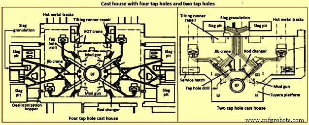
Fig 14 Cast house with four tap holes and two tap holes
Mud gun – The mud gun is used to close the tap hole after tapping is complete. A quantity of the tap hole mass is pushed by the mud gun to fill the worn hole and to maintain a quantity of the tap hole mass (the mushroom) within the hearth. The mud gun is normally held in place on the tap hole until the tap hole mass cures and the tap hole is securely plugged. A hydraulic mud gun uses hydraulic power to swing, hold, and push the tap hole mass. Typical injection pressure of tap hole mass is of the order of 20 MPa to 25 MPa, permitting it to push viscous mass into the furnace operating at high pressures. The hydraulic gun is held against the furnace with the equivalent of 15 tons to 35 tons of force. This type of mud gun can be swung into place in one motion.
An electro-mechanical gun has three separate electric drives for unit swing, barrel positioning, and ramming. Hence several separate motions are needed for accurate positioning of the mud gun at the tap hole. Tap hole mass injection pressure is in the range of only 5 MPa to 8 MPa. The electro-mechanical mud gun is latched to the furnace to keep it in place during plugging.
Tap hole drill – Tap hole drill is used to bore a hole though the tap hole clay into the hearth of the furnace. A drill unit is swung into place hydraulically and held hydraulically in the working position. A pneumatic motor feeds the hammer drill unit (with an attached drill rod and bit) into the hole. Compressed air is fed down the centre of the drill rod and the drill bit to cool the bit and blowout the removed tap hole mass. When the tap hole drill rod has penetrated into the hearth, the drill rod is retracted and the drill swings clear of the hot metal stream.
Soaking bar technique – The application of the soaking bar practice has improved the tapping process. When the tap hole mass is still pliable after plugging, a steel bar is driven into the tap hole by the tap hole drill. While the bar sits in place during the time between casts, it heats up by conduction from the hearth hot metal. This permits curing of the tap hole mass along its entire length (as opposed to curing with the furnace and setting at the outside near the furnace cooling elements). The cured tap hole mass is more resistant to erosion during tapping, hence improving tap flow rate control. Less tap hole mass is needed to replug the hole. When the tap hole is to be opened, a clamping device and a back hammering device on the tap hole drill extract the rod. The timing for tap hole opening can be more easily controlled (predicted) than by conventional drilling. This feature is important for smooth furnace operation and for scheduling of hot metal delivery to downstream facilities.
Same side tap hole equipment – Mud gun and drills have normally been installed on opposite sides of the tap hole. Design development has permitted installation of these equipments on one side of the tap hole. The drill swings over the mud gun or vice versa. This type of installation facilitates improved access for tap hole and trough maintenance and the improved application of trough and tap hole area flue collection.
With the advent of tuyere access platforms to facilitate tuyere and tuyere stock inspection and replacement, the headroom available for the tap hole equipment has diminished. However, same side tap hole equipment installations can be achieved with low headroom (for example 2.2 metres).
Trough and runner system – Typical hot metal and slag tapping rates are in the range of 4 to 6 tons per minute and 3 to 5 tons per minute, respectively. The trough and runner systems are to be designed to properly separate the iron and slag and to convey them away from the furnace for flow rates within the normal flow rate range and for unusual peak flow rates.
The hot metal trough (Fig 15) is a refractory lined tundish located in the cast house floor and designed to collect iron and slag after discharge from the furnace. The hot metal flows down the trough, under a skimmer and over a dam into the hot metal runner system. The hot metal level in the trough is dictated by the dam. Proper dam design submerges the lowest portion of the skimmer in the hot metal pool. The slag, being lighter than the hot metal, floats down the trough on top of the hot metal pool. Since it cannot sink into the hot metal and through the skimmer opening, it pools on top of the hot metal until sufficient volume collects to overflow a slag dam and run down the slag runner. At the end of the tapping, the slag runner dam height is lowered to drain off most of the slag. The residual hot metal is retained in the trough to prevent oxidation and thermal shock of the trough refractory lining.
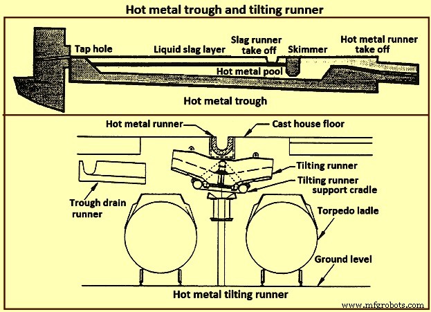
Fig 15 Hot metal trough and tilting runner
When maintenance of the trough lining is needed, the hot metal pool can be dumped by removing the hot metal dam, or by opening a trough drain gate, or by drilling into the side of the trough (at its lowest point) with a drain drill. The trough bottom is normally designed with a 2 % (minimum) slope for effective draining. Trough cross-section and length design are important for effective iron and slag flow pattern, retention, and separation. A good trough design results in hot metal yield improvements. Effective trough lining and cooling techniques are important for lining life, hot metal temperature, and cast house structural steel and concrete heat protection considerations. Troughs traditionally were contained in steel boxes ‘buried in sand’ in the cast house floor system. Improved trough design incorporates forced or natural air convection or water-cooling.
Cast house practice needs the runners to be as short as possible. This minimizes temperature loss of hot metal and reduces runner maintenance and flue generation. Shorter runners can also result in reduced capital expenditure for cast house building installation or modification. Since the runners are to slope away from the furnace, the cast house floor normally follows the same slope as the runners.
Slag runners are normally designed with a 7 % (minimum) slope. Slag can be directed to (i) slag pots for railway or mobile equipment haulage to a remote site for dumping, (ii) slag pits adjacent to the furnace for air cooling and water quenching prior to excavation by mobile equipment, and (iii) granulation facilities adjacent to the furnace for conversion of the liquid slag to granulated slag. Granulation units are provided with systems to eliminate flue emissions associated with environmental issues.
Hot metal runners are normally designed with a 3 % (minimum) slope. Hot metal is normally directed to hot metal transfer ladles (torpedo cars / open top ladles) for movement to the steel melting shop or pig casting machines. While normal practice used is to have one iron runner system with diverter gates directing the hot metal to different pouring positions, each with a ladle. Application of the tilting runner practice has been beneficial. A tilting runner is normally with an electrical motor-driven actuator (with a manual hand wheel back-up), and is tilted at around 5 degrees to divert the hot metal. A pool of hot metal is held in the tilting runner to minimize splashing and refractory wear. When one hot metal ladle has been filled, the runner is tilted to the opposite side to fill the other ladle. If needed, a locomotive removes the filled ladle and spots an empty ladle in its place. This operation can be done without plugging the furnace. When the tapping is finished, the tilting runner is tilted an additional 5 degrees to dump its pool of hot metal into the ladle.
Modern cast house design includes flat floors, where the runner is fully covered and is fitted flush with the floor. This allows safer and easier use of mobile vehicles in the cast house area. The use of radio controlled equipment and other devices have helped to reform cast house work, and these, along with effective emission control systems, have improved working conditions. As the BF hearth diameter is increased, there is a resulting need to increase the size of the cast-house. Large BF are normally designed with four tap holes (Fig 14). With a four top-hole configuration, the cast-house arrangement needs to provide sufficient space for movement around the floor itself. There is no design issues associated with this requirement as long as there is the necessary space provided in the site plan. Increasing the size of the cast-house in terms of floor plan does not represent a radical change in design philosophy which can pose a challenge the furnace designer. An efficient and strictly controlled tapping is necessary for ensuring a stable operation and high productivity of the BF.
Emission control
Fume collection requirements and applications appear to vary considerably around the globe. BFs presently have full, partial, or even no cast house fume collection system. Exhaust fan and bag house capacity of the order of 9,000 cubic meter per minute (cum/min) to 11,500 cum/min (depending upon operation and design practices) is typical for full flue capture of a two tap hole cast house installation (for trough runners and tilting runners).
Proper design and application of flue collection runner covers can facilitate cast house access (i.e. flat floor configuration using steel slabs or plates) for personnel and mobile equipment crossover. Runner covers can also reduce hot metal temperature loss and improve runner refractory longevity.
Some furnaces use flame suppression which eliminates the oxygen in the air directly over the trough and iron runners. Products of combustion prevent oxidation of the hot metal surface reducing visible particulate and flues.
Other aspects of BF design
It is necessary that complete study of every element in the process chain, from raw materials delivery to hot metal consumption is made to ensure that there are no ‘bottle necks’ in the system which can prevent the furnace from meeting the goals of its installation. While designing the BF, thought process is to be used to develop the furnace design and some alternatives are to be considered before freezing the design. During the designing of the furnace, those furnace equipments are to be selected which best meet the needs of the furnace operation.
The furnace design is to ensure (i) the furnace is capable of meeting the operational goals of production, productivity (tons per day per cubic metre of working volume), specific consumptions (kilograms per ton of hot metal), and product quality in cost effective manner, (ii) the furnace has the flexibility to accept and absorb the changes in the quality of the raw materials, and (iii) the furnace is capable of achieving the desired campaign life both with respect to time and the total production.
Financial justification is the over-riding consideration for the design. For this purpose, the economic study is to be very extensive. Further, the furnace design is to include latest technological developments so that the furnace does not become technologically outdated during its entire campaign.
The working volume of the furnace is the internal volume of the furnace calculated between the tuyeres and the stock line. Hearth productivity of the furnace is rated in tons per day per cubic metre of active hearth volume. Active hearth volume is the internal volume of the furnace calculated between the tuyeres and the tap hole. Active hearth volume is a measure of the holding capacity of the furnace for the liquids produced in the working volume (above the tuyeres). Hence, the tons per day per cubic metre of active hearth volume is a measure of the specific capacity (through-put per unit volume) of the hearth of the BF.
The design of the hearth is very important since it has a strong effect on the furnace operation. The furnace operation gets affected since the hearth liquid levels change rapidly which cause variations in gas flow pattern, gas utilization, and blast pressure. Also, because of these rapid changes in liquid level, there can be jamming / burning of the tuyeres which affect the blowing of the furnace.
The furnace hearth volume also determines the controls the operator is to exercise during furnace operation. For a very good hearth liquid level control, the high through-put furnace need around 90 % time spent in tapping. To make this time of tapping possible, cast floor is to be designed properly.
The furnace lining and cooling system needs special attention so that it does not pose any problem during the entire campaign of the BF. The selection of refractories, cooling elements, and internal furnace geometry is very important in this respect. Copper staves in this respect are expensive but they are very economical in comparison to the alternatives. Carbon lining of the hearth is very important for the long life of the hearth. The refractory lining thickness of the stack has implication on the furnace working volume.
The production needed normally determines the size of the BF. However, for the sizing of the BF, the raw materials, the product chemistry, and even operating philosophy are important. While the furnace size has implication on the capital cost, the productivity improvement has implication on the operating cost. The specific productivity of the furnace is to be determined for the determination of the size of the BF needed to produce the required quantity of hot metal. From the wide range of possible operating rates, the working volume of the furnace is to be calculated. Productivity and hence the furnace size is also to be based on the fuel rate. The fuel rate is dependent on the quality of raw materials, hot blast parameters, hot metal quality, and the operating philosophy.
The size is the most important factor for the determination of the BF productivity. However, there are other factors which also influence the BF productivity. The most important of these factors include (i) hot blast temperature and pressure, (ii) high top pressure, (iii) oxygen enrichment of the air blast, (iv) injection of auxiliary fuel at the tuyere, (v) prepared burden (sinter, pellets etc.), (vi) Fe content of the ferrous burden, (vii) ash in coke, (viii) quality of the coke, (ix) moisture content of the burden, (x) direct charging of fluxes (lime stone, dolomite etc.) in the BF, (xi) content of fines in the burden, (xii) quality of hot metal to be produced, (xiii) burden distribution control in the furnace, and (xiv) level of automation and control in the furnace.
The availability of furnace equipment, provision of stand-by equipment, and the maintenance philosophy are important factors which have high influence on the annual production from the BF. Further, incorporation of safe and healthy working practices during the operation of BF in the design of the BF is important which has a high influence on the furnace productions. In this regards, safety interlocks are to be provided at all the places where there exist a chance of unsafe operating practices to take place.


