Evolusi Pembuatan Besi Tungku Ledakan
Evolusi Pembuatan Besi Tungku Ledakan
Asal mula peleburan besi pertama tersembunyi dalam sejarah peradaban manusia yang tidak tercatat. Bukti pertama alat besi yang digunakan di zaman kuno sebenarnya berasal dari Mesir di mana alat besi ditemukan di sambungan antara dua batu di piramida. Asal usul banyak peralatan besi prasejarah mungkin adalah besi meteorik. Besi meteorik mengandung 5 % sampai 26 % nikel (Ni) sedangkan besi yang dilebur hanya mengandung sedikit Ni dan karenanya artefak besi yang terbuat dari meteor dapat dibedakan dari benda-benda dari besi yang dilebur.
Lebih dari 4.000 tahun yang lalu, orang menemukan besi meteor. Tapi itu 2.000 tahun lagi sebelum produksi besi dari bijih besi yang ditambang dimulai. Penemuan besi lebur paling awal di India berasal dari tahun 1800 SM (Sebelum Era Umum). Peleburan besi dikatakan telah terjadi di antara Kalibes Armenia, subjek Kekaisaran Het, sekitar tahun 1500 SM. Ketika kerajaan mereka runtuh sekitar 1200 SM, berbagai suku membawa pengetahuan pembuatan besi, menyebarkannya ke seluruh Eropa dan Asia. Pengetahuan tentang pengerjaan besi di seluruh Eropa dan Asia Barat pada akhirnya ditelusuri ke sumber ini. Zaman Besi dimulai dengan penemuan peleburan besi.
Awal peleburan besi
Seperti halnya reduksi bijih tembaga sulfida, reduksi pertama oksida besi mungkin tidak disengaja. Kekuatan pengamatan inilah yang membuat ahli metalurgi kuno ini (yang merupakan penambang, ahli kimia, dan teknologi pada zaman mereka) menyadari bahwa besi dapat diproduksi dalam tungku sederhana dengan reduksi karbon (C) langsung dari bijih oksida. Penggambaran rekaman pertama dari proses peleburan ditemukan di dinding makam Mesir yang berasal dari sekitar 1500 SM. (Gbr. 1) Proses ini adalah lubang sederhana dengan bijih dan bahan bakar yang tidak diketahui yang membuat api semakin intensif melalui penggunaan bellow yang dioperasikan dengan kaki. Selama 3000 tahun berikutnya, teknik produksi besi tidak berubah secara signifikan dengan spons besi yang dihasilkan oleh reduksi C dari oksida dan produk besi yang dibuat dengan menumbuk spons.
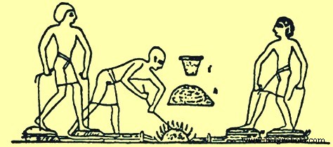
Gbr 1 Proses peleburan besi yang digambarkan di makam Mesir
Bijih besi oksida terdapat di banyak area di planet bumi. Jadi, kira-kira pada saat yang sama ketika reduksi bijih besi terjadi di Mesir, hal itu juga sedang dilakukan di daerah lain. India, Cina, Afrika, dan Malaya menjadi tempat pengembangan awal praktik pembuatan besi ini. Mungkin signifikan bahwa tungku yang dikembangkan di negara-negara ini semuanya sangat mirip. Ada perbedaan dalam bentuk dan ukuran, tetapi tungku secara fungsional identik Reduksi kimia menjadi besi terjadi tanpa meleleh, dan logam yang dihasilkan relatif murni dan lunak dan disebut besi tempa. Dapat dipalu menjadi bentuk yang berguna. Tombak, ujung panah, belati, dan alat serta senjata lainnya dapat dibuat dari ini besi tempa.
Selama sekitar 2000 tahun, sampai sekitar akhir milenium pertama M (Era Umum), besi diproduksi di perapian lokal kecil dengan proses 'mekar'. Ukuran struktur ini tidak tersedia dalam penyelidikan arkeologi tetapi rekonstruksi modern dari tungku mekar memiliki dimensi internal 300 mm diameter. x 1000mm tinggi. Dalam proses mekarnya perapian dibangun dan di dalamnya ditempatkan beberapa lapisan arang dan bijih besi sampai gundukan dihasilkan. Di sekitar gundukan ini dibangun selubung dari tanah liat dan batu bata yang meninggalkan lubang di bagian atas untuk gas buang dan lubang di bagian bawah untuk semburan udara yang dihasilkan dari pengoperasian bellow. Arang kemudian dinyalakan dan bellow dioperasikan sampai arang habis. Selongsong kemudian dibuka, dan jika prosesnya berjalan dengan baik maka ada tumpukan besi spon dan genangan terak. Besi spons panas dipukul dengan palu untuk menghasilkan billet besi atau produk besi. Reaksi yang terjadi selama peleburan dalam proses mekar dijelaskan di sini. Api arang menghasilkan karbon monoksida (CO) dan panas mengusir air dari bijih rawa untuk menghasilkan hematit. CO mereduksi hematit menjadi oksida besi, wüstite. CO kemudian mereduksi wüstite menjadi unsur besi. Reaksinya tidak berjalan sepenuhnya; itu berlanjut ke posisi kesetimbangan dan gas yang dihasilkan adalah campuran CO dan karbon dioksida (CO2). Namun, wüstite juga dapat bereaksi dengan pasir apa pun untuk menghasilkan olivin besi, (fayalit), yang merupakan komponen utama terak yang dihasilkan. Fayalite ini adalah jalan buntu sejauh proses peleburan yang bersangkutan karena tidak dapat direduksi menjadi unsur besi di bawah kondisi tungku. Besi yang dihasilkan memiliki titik leleh sekitar. 1.540 derajat C, sedangkan titik leleh terak sekitar 1.100 derajat C. Suhu yang dicapai cukup tinggi untuk melelehkan terak, tetapi tidak cukup tinggi untuk melelehkan besi. Prosesnya berjalan cukup baik, meskipun terak yang tersisa masih mengandung banyak zat besi, seringkali hingga dan lebih dari 60% FeO (ferrous oxide). Terak terdiri dari dua jenis, sebagian dari sifat berpori terbuka dari sampah bijih rawa, dan sebagian padat, keras, dan sangat tidak dapat meresap, seperti yang diperoleh dari bijih besi merah.
Perkembangan dalam proses pembuatan besi
Perbaikan pada proses pembuatan besi pertama ini dilakukan dengan melapisi lubang peleburan dengan batu serta lumpur dan menggunakan bellow yang terbuat dari kayu dan kulit (Gbr 2). Di Cina, penggunaan besi muncul sekitar 600 SM, menyebar luas selama periode 403 SM hingga 222 SM. Orang Cina mengembangkan teknologi pembuatan besi yang unggul dan besi cair diproduksi sedini 200 SM berdasarkan penemuan peralatan besi cor. Tulisan-tulisan kuno di Cina dan India mengacu pada peleburan besi. Artefak lainnya termasuk pedang, kapak, sabit dan cangkul. Pada tahun 310 CE, jumlah besi yang cukup dapat diproduksi untuk memungkinkan pendirian pilar besi yang terkenal di Delhi dan Dhar di India. Tiang besi tempa di Delhi tingginya 18 m, diameter 410 mm dan berat 17 ton. Di Jepang, proses pembuatan besi dan baja tradisional yang dikenal sebagai 'Tatara' tidak sepenuhnya berkembang sampai abad ke-17 Masehi. Di Amerika Utara, Amerika Selatan dan Australia, peleburan besi tidak diketahui oleh penduduk kuno. Teknologi pembuatan besi dibawa ke negara-negara ini oleh orang Eropa.
Proses pembuatan besi yang dikembangkan di sekitar Laut Mediterania telah menyebar ke utara melalui Eropa. Orang Fenisia, Kelt, dan Romawi membantu menyebarkan teknologi pembuatan besi. Salah satu teknik pembuatan besi yang disebarkan oleh orang Romawi ke utara sejauh Inggris Raya adalah tungku mangkuk atau tungku poros awal. Tungku ini terdiri dari bejana berbentuk mangkuk atau poros silinder setinggi 2 m yang dibangun di sisi bukit. Udara yang digunakan untuk mengipasi api di dalam tungku disediakan oleh lubang yang dibangun di dekat bagian bawah mangkuk yang menghadap ke angin yang ada. Tungku diisi melalui bukaan atas dengan lapisan arang dan bijih besi yang dinyalakan melalui bukaan bawah.
Ada dua teori tentang bagaimana peleburan besi didorong, satu bahwa angin bertiup melalui bukaan bawah yang menyediakan udara yang memanaskan proses dan yang lain bahwa angin bertiup dari atas yang terbuka, menciptakan area bertekanan rendah di sepanjang dinding depan bagian dalam. yang menyedot udara masuk melalui bukaan bawah (Gbr 2). Dalam kedua kasus tersebut, prosesnya bergantung pada angin dan tidak dapat diandalkan sepanjang tahun. Produk ini sekali lagi merupakan massa besi spons, yang dikeluarkan melalui bukaan bawah dan kemudian ditempa menjadi bentuk akhirnya.
Jenis lain dari peleburan besi awal adalah tungku sarang lebah (Gbr 2). Tungku ini dibangun di atas tanah datar dengan menumpuk lapisan arang dan bijih besi secara bergantian. Gundukan itu ditutupi dengan lapisan tanah liat yang tebal dan pipa tiup yang terhubung ke bellow dimasukkan melalui dinding sisi bawah. Lapisan bawah arang dinyalakan dan udara bertekanan disediakan oleh penghembus. Pada akhir peleburan jenis batch ini, kubah tanah liat runtuh. Besi spons yang dihasilkan digali dari tungku sarang lebah yang dihancurkan untuk dipalu. Produksi di tungku ini adalah gumpalan kecil besi dan tungku peleburan harus dihancurkan dan dibangun kembali setelah setiap produksi berjalan.
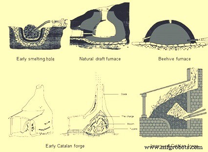
Gbr 2 Proses awal pembuatan besi
Jenis proses pembuatan besi ini digunakan selama beberapa ratus tahun hingga era modern tanpa banyak perbaikan. Kemudian kira-kira selama abad kedelapan, sebuah bengkel kecil yang beroperasi di pegunungan Catalonia di timur laut Spanyol mewakili salah satu kemajuan metalurgi awal yang signifikan dalam pembuatan besi. Penempaan Catalan awal (Gbr 2) memiliki cangkir yang terbuat dari batu yang disebut perapian, dengan tinggi sekitar 910 mm dan diameter 760 mm. Jarak pendek di atas bagian depan pangkalan adalah lubang kecil yang memungkinkan dipasangnya nosel yang dikenal sebagai tuyere. Nosel tuyere terhubung ke bellow untuk suplai udara. Perapian diisi ke tingkat tuyere dengan gumpalan arang. Kemudian bijih besi ditempatkan di atas tuyere dan lebih banyak arang berlapis di atas bijih. Arang dinyalakan dan udara dari penghembus memaksa CO panas ke atas bijih yang mereduksi bijih besi menjadi massa besi yang panas dan kental. Massa besi yang dikenal sebagai bunga mekar dapat mencapai berat 160 kg dan dapat dikeluarkan dari perapian bengkel dengan penjepit tanpa merusak struktur batu. Jumlah besi ini dapat dihasilkan dalam 5 jam sementara teknologi sebelumnya hanya dapat menghasilkan sekitar 23 kg dalam 5 jam. Tempa Catalan bertambah besar ukurannya selama 200 tahun berikutnya dan penggunaannya menyebar ke Prancis, Belgia, Inggris, dan Jerman. Ukuran perapian meningkat menjadi 1 m persegi dan dibangun dari balok batu persegi panjang. Kuantitas udara yang dikirim melalui tuyere juga ditingkatkan melalui penggunaan aspirator udara yang dikenal sebagai 'trompe'. Saat air jatuh melalui kolom trompe, udara ditarik ke dalam tabung dan kemudian dikeluarkan di bagian bawah kotak. Ketika perangkat ini dimasukkan ke dalam Catalan Forge, tekanan ledakan melalui tuyere adalah 0,10 hingga 0,14 kg/cm persegi yang secara signifikan lebih dari yang bisa dihasilkan oleh penghembus tangan atau kaki. Tekanan ledakan tambahan ini mempercepat proses peleburan dan meningkatkan produksi.
Dari abad ke-10 hingga abad ke-14, bengkel Catalan mengalami evolusi lebih lanjut. Bellow yang dioperasikan dengan tangan atau kaki diganti dengan bellow yang dioperasikan dengan kincir air dan ini meningkatkan volume dan tekanan ledakan udara. Selanjutnya dilakukan upaya untuk menangkap panas buangan dari tumpukan tempa dengan cara menambah tinggi tumpukan dan pengisian bijih besi dan arang dari atas tumpukan agar bijih dapat dipanaskan terlebih dahulu. Tungku ini memiliki tumpukan yang terbuat dari pasangan bata dengan tinggi 1,8 m hingga 4,8 m. Ketinggian tumpukan dan karena itu ketinggian muatan bahan baku dapat meningkat karena tekanan ledakan yang lebih tinggi yang dapat memaksa tumpukan ini dari kincir air yang dioperasikan.
Tungku Stuckofen (Gambar 3) yang tertinggi tidak hanya memiliki tinggi cerobong 4,8 m tetapi juga perubahan geometri cerobong. Tungku berbentuk dua kerucut terpotong yang dihubungkan pada diameter terlebar. Dua tuyer menjadi standar karena kincir air menggerakkan dua bellow dengan salah satunya terus-menerus dikompres untuk menghasilkan ledakan. Ada lubang di bagian bawah tungku untuk mengeluarkan terak tetapi pekerjaan batu harus dihilangkan untuk mengekstrak produk akhir yang masih berupa gumpalan besi dengan berat sekitar 318 kg. Tungku Stuckofen dapat menghasilkan 100 hingga 150 ton dalam setahun yang melampaui kemampuan produksi bengkel Catalan. Salah satu produk sampingan dari tungku ini adalah besi cair. Karena bijih besi memiliki waktu tinggal yang lebih lama di tungku untuk mengalami reaksi kimia dan terkena suhu yang lebih tinggi, besi dapat menyerap lebih banyak C yang menurunkan titik leleh. Ketika mekar dikeluarkan dari tungku, besi cair ini juga dihilangkan. Pada awalnya dianggap merugikan karena terlalu rapuh untuk dikerjakan dengan palu. Dalam beberapa kasus, itu diisi ulang ke dalam tungku atau bahkan dibuang sebagai limbah. Tungku Stuckofen dianggap sebagai cikal bakal blast furnace (BF) modern. Itu dimodifikasi lebih lanjut menjadi 'Blauofen' (oven tiup) yang mampu menghasilkan besi cair atau besi spons tingkat penempaan sesuai kebijaksanaan pembuat besi. Perubahan pada produk yang diinginkan ini dicapai dengan mengubah jumlah bahan bakar yang diisikan sebesar 10% menjadi 15% dan dengan menurunkan posisi tuyer sebesar 500 mm dan mendorongnya lebih dalam ke dalam tungku. Pada abad ke-16 tungku ini setinggi 6,7 m dan dapat menghasilkan sekitar 1,8 ton besi per hari dengan laju bahan bakar sekitar 250 kg arang per 100 kg besi yang dihasilkan. Tungku ini memiliki harapan hidup sekitar 45 hari.
Langkah selanjutnya dalam desain tungku untuk menghasilkan besi cair sepanjang waktu adalah 'Flussofen' (oven aliran). Perkembangan Flussofen atau BF pertama terjadi pada abad ke-14 di Lembah Sungai Rhine dan daerah yang berdekatan dengan Perancis, Belgia dan Jerman. Namun, dengan perubahan teknologi peperangan serta pembuatan besi, pengecoran meriam dari besi cair menjadi industri yang dominan daripada penempaan pedang dari besi spons. Pada awal 1300 CE, pembuat besi secara aktif berusaha untuk memproduksi besi cair untuk melemparkan senjata. Dokumentasi pertama yang dapat diandalkan dari BF yang diketahui adalah pada tahun 1340 M ketika tungku di Marche Les Dames, di Belgia dibangun. Penyebaran Flussofen atau BF relatif lambat. Negara-negara kontinental di Eropa berhak atas pujian karena telah sepenuhnya mengembangkan BF dari metode primitif menghasilkan bunga besi di bengkel Catalan. BF modern adalah tungku poros yang secara bertahap berevolusi dari Stuckofen dan Flussofen.
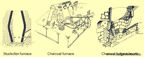
Gbr 3 Tungku Stuckofen dan tungku arang
Evolusi tanur sembur arang
BF arang (Gambar 3) yang dikembangkan di Eropa Kontinental segera menyebar ke Inggris Raya di mana evolusi berikutnya dalam teknologi pembuatan besi telah terjadi. BF yang dibangun di Monmouthshire, Inggris pada tahun 1565 M adalah tungku pertama yang dibangun di hutan Dean yang menjadi pusat pembuatan besi utama. BF ini memiliki tinggi 4,6 m dan 1,8 m di bagian atas, titik terlebar di dalam tungku tempat dua kerucut terpotong bertemu. Pada 1615 CE ada 300 BF rata-rata sekitar 2 ton per hari per tungku. Laju pertumbuhannya sangat cepat sehingga menyebabkan deforestasi total lahan untuk produksi arang. Selama tahun 1600-an, pembatasan hukum diberlakukan untuk melindungi hutan yang tersisa dan banyak BF ditutup.
BF pertama yang dibangun di Amerika Utara berada di Falling Creek, Virginia pada tahun 1622. Tungku ini tidak pernah dioperasikan karena semua pekerja pabrik terbunuh dan besi dihancurkan oleh penduduk asli Amerika. BF arang pertama yang berhasil di Amerika Utara adalah di Saugus, Massachusetts, mulai tahun 1645. BF ini memiliki tumpukan setinggi 6,4 m dengan dinding luar miring ke dalam saat naik dan 7,9 m persegi di dasarnya. Tungku terbuat dari granit dan batu lokal lainnya yang diikat dengan mortar tanah liat. Itu beristirahat di tanah datar di mana sistem drainase bawah tanah telah dipotong untuk menjaga dari kelembaban yang membuat air yang menggerakkan roda penghembusnya yang besar membuatnya sangat rentan. BF memiliki tumpukan dengan interior berbentuk telur dan dengan diameter maksimum yang dikenal sebagai bagian atas bosh adalah 1,8 m. Bosh, yang miring ke bawah, mendukung muatan bijih, fluks, dan arang. Sebuah wadah persegi yang disebut perapian berada di bawah bagian bawah bosh dan dilapisi dengan batu pasir (Gbr 3). Ada dinding bagian dalam dengan pasir, tanah liat dan puing-puing antara lapisan dalam dan pasangan bata luar yang bertindak sebagai bantalan untuk ekspansi dan kontraksi selama siklus pemanasan dan pendinginan. Ada lengkungan besar dan dalam di dua dinding luar. Melalui lengkungan yang lebih kecil melewati hidung dua bellow 5,5 m dan dua tuyer, yang mengirimkan ledakan ke BF. Di bawah lengkungan yang lebih besar adalah area kerja perapian dan lantai pengecoran. Wadah atau perapian bertindak sebagai reservoir untuk besi cair. Perapian berukuran 460 mm persegi di bagian dasarnya tetapi diperluas menjadi 530 mm saat mencapai ketinggian penuh 1,1 m. Sebuah proyeksi bagian bawahnya, yang disebut perapian depan, terdiri dari dua dinding dan satu hutan atau bendungan. Di atas, dan mundur dari bendungan, ada dinding tirai batu, yang disebut 'tymp', yang tepi bawahnya turun lebih rendah dari bagian atas bendungan. Melalui lubang antara tymp dan bendungan, seorang operator menyendok besi untuk pengecoran cetakan dan dengan batang besi, yang disebut ringer, mencabut terak yang menempel di dinding atau menumpuk di sekitar hidung tuyere. Untuk perlindungan terhadap keausan operasi tersebut, baik tymp dan bendungan dilapisi dengan pelat besi. Penghapusan terak dilakukan dengan menyapu bahan cair di atas batu bendungan di lokasi yang disebut takik cinder. Namun untuk menyadap besi tersebut, diperlukan pemutusan sumbat tanah liat yang dimasukkan ke dalam ruang sempit, yang disebut lubang keran, antara salah satu dinding samping perapian depan dan salah satu ujung bendungan.
Selain pekerjaan pasangan bata yang rumit ini, pemasangan BF melibatkan pekerjaan kayu dan kulit. Di antara puncak BF dan tebing yang berdekatan terdapat struktur kayu berat yang disebut jembatan pengisian. Bahan baku diambil dengan gerobak dorong dari timbunan mereka di tebing, melintasi jembatan pengisian ke puncak BF. Di tiga sisi bagian atas BF terdapat kasa angin dari kayu, yang dipasang untuk menyediakan tempat berlindung yang aman bagi operator yang mengisi bahan mentah ke dalam lubang pengisian yang mengeluarkan asap, percikan api, dan kadang-kadang api. Tumpukan BF di permukaan tanah dibungkus di dua sisi oleh struktur kayu yang disebut rumah pengecoran. Struktur ini menyediakan penutup untuk parit dan area pengecoran cetakan serta bellow. Kedua bellow didorong secara bolak-balik oleh poros bubungan yang terhubung ke kincir air yang melampaui batas. Bellow dikempiskan oleh Cams pada poros utama dan dipompa oleh counterweight yang terdiri dari kotak kayu yang diisi dengan batu dan dipasang pada balok bergerak yang memanjang di luar atap rumah pengecoran melalui lubang yang dipotong untuk menampungnya. BF mengkonsumsi 3 ton bijih besi, 2 ton batu fluks dan 2,6 ton arang per ton besi yang diproduksi. Lubang keran dibuka dua kali sehari dan sekitar 450 kg besi cair dikeluarkan selama setiap cor. Setrika cair ditarik ke dalam parit tunggal atau disendok ke dalam cetakan pasir untuk menghasilkan produk dalam negeri seperti panci, wajan, piring kompor, dll.
Pembuatan besi arang yang dijelaskan di atas hanya berubah sedikit selama 100 tahun berikutnya hingga 1700-an. Tumpukan BF meningkat dalam ukuran dan perbaikan dilakukan pada peralatan bertiup. BF arang khas tahun 1700-an memiliki ukuran tinggi 9,1 m dan diameter bosh 2,4 m yang meningkat. Peningkatan ukuran BF hanya dimungkinkan melalui perbaikan pada peralatan pengiriman angin yang menghasilkan tekanan ledakan yang lebih tinggi. Peningkatan pertama dalam sistem ledakan adalah penemuan bak peniup kayu yang berbentuk persegi atau bulat dan mirip dengan tong kayu yang disatukan dengan lingkaran baja eksternal. Sebuah engkol eksentrik pada kincir air memiliki batang piston bolak-balik dan bak peniup di setiap sisi. Piston di dalam bak dilengkapi dengan kulit untuk membentuk segel. Saat satu piston naik untuk memampatkan udara di satu bak, piston lainnya turun di bak lainnya. Di bagian atas setiap bak adalah pipa keluar yang terhubung ke kotak pencampuran umum yang selalu berada di bawah tekanan. Kotak pencampur diumpankan udara tekan ke saluran udara atau ledakan utama yang mengarah ke tungku tuyeres. Sebuah bak peniup tipikal berdiameter 1,8 m dan tinggi 1,8 m, menghasilkan tekanan ledakan 0,14 kg/cm2. Konsep bak tiup kayu dibawa satu langkah lebih jauh pada tahun 1760 oleh John Smeaton dari Inggris. Dia mengubah bak kayu menjadi bak besi cor yang digerakkan pertama kali oleh kincir air dan kemudian pada tahun 1769 oleh mesin uap. BF pertama yang menggunakan mesin peniup yang digerakkan oleh uap dibangun di Skotlandia pada tahun 1769. Penemuan mesin peniup yang digerakkan oleh uap telah menghasilkan tekanan ledakan yang lebih tinggi yang memungkinkan penggunaan lebih lanjut bahan bakar mineral (kokas dan batu bara). Peningkatan 1700-an ini menyebabkan produksi BF meningkat menjadi 3 hingga 5 ton/hari pada akhir 1700-an dari satu ton/hari pada 1600-an BF. Ini bersama dengan penggunaan bahan bakar mineral menyebabkan penurunan cepat dalam jumlah tungku arang di Eropa, meskipun kapasitas besi arang meningkat di Amerika Utara karena populasi pindah ke barat di mana ada ketersediaan kayu yang besar.
Pada 1800-an, produksi besi arang mencapai puncaknya dan kemudian menurun. Pada pertengahan 1800-an, bijih besi berkualitas tinggi ditemukan di Pennsylvania dan Upper Peninsula of Michigan yang memiliki hutan perawan yang lebat. BF arang yang dibangun di area ini adalah yang terbesar dan paling lengkap. BF ini memiliki tinggi tumpukan 13,7 m dan diameter bosh 2,9 m. Jumlah tuyer meningkat dari dua menjadi tiga, masing-masing satu di tiga sisi tungku sedangkan lubang keran berada di sisi keempat. Peralatan peniup biasanya silinder peniup horizontal dengan diameter tipikal hingga 1270 mm dan langkah 1,5 m. Kerekan platform tipe elevator menggantikan jembatan pengisian dan semua bijih besi serta fluks ditimbang sebagai bagian dari muatan standar. Arang masih terisi oleh volume gerobak dorong yang besar. Pelat cangkang besi perlahan menggantikan tumpukan batu bata dan lapisan batu alam ditingkatkan menjadi batu bata alumina.
Salah satu peningkatan teknologi utama yang dipasang pada tungku arang ini adalah peralatan pengisian daya. Awalnya, bahan mentah dibuang ke tumpukan dengan mulut terbuka melalui kepala terowongan. Operator BF menyadari bahwa tungku atas terbuka memiliki dua kelemahan, pertama gas yang mudah terbakar meninggalkan cerobong tidak dapat ditangkap untuk menyalakan boiler dan kedua, distribusi bahan baku menyebabkan inefisiensi operasi tungku. Upaya pertama pada tahun 1832 di Jerman untuk menangkap gas menghasilkan pemasangan tutup berengsel di atas lubang pengisian yang hanya dibuka ketika bahan mentah dibuang dari gerobak dorong (Gbr 4). Bukaan juga ditempatkan di sisi tungku yang terletak di tumpukan atas. Bukaan ini dilengkapi dengan pipa yang dikenal sebagai down comer yang membawa gas BF ke permukaan tanah untuk dibakar di peralatan bantu.
Masalah inefisiensi BF karena pengisian bahan baku membutuhkan solusi yang lebih rumit yang berkembang dalam beberapa langkah. Penyebab ketidakefisienan ini, yang dijelaskan oleh tingkat bahan bakar yang tinggi, adalah karena bahan halus yang dibuang melalui lubang pengisian di tengah BF tetap berada di tengah tumpukan sementara partikel kasar berguling ke dinding tungku. Hal ini mengakibatkan permeabilitas yang lebih tinggi di pinggiran BF dan sebagian besar gas dan panas pindah ke dinding. Hal ini merugikan operasi BF karena material di bagian tengah BF yang dicapai di area bosh tidak siap untuk meleleh dan pada saat yang sama aliran gas yang berlebihan di dinding meningkatkan keausan lapisan. Upaya pertama untuk memecahkan masalah distribusi beban ini adalah pengenalan peralatan pengisian 'cangkir dan kerucut' (Gbr 4). Itu terdiri dari corong besi cor berbentuk kerucut terbalik yang dipasang di bagian atas tungku yang memberi makan lubang pengisian. Kerucut ini sekitar 50% dari diameter tenggorokan. Di dalam kerucut itu duduk sebuah cangkir besi tuang, yang digantungkan pada balok tumpu di seberang sebuah penyeimbang. Cangkir diangkat secara manual dengan menggunakan winch yang terhubung ke counterweight. Aparat ini berhasil menangkap gas tetapi masih banyak material kasar yang terguling ke dinding. Modifikasi selanjutnya pada peralatan cangkir dan kerucut adalah menggantung kerucut terpotong besi cor di dalam tungku (Gbr 4). Hal ini mengakibatkan perpindahan puncak bahan mentah lebih dekat ke dinding sehingga partikel kasar sekarang juga dapat menggelinding ke tengah tungku sehingga menghasilkan permeabilitas pusat dan aliran gas yang lebih baik.
Langkah evolusi berikutnya dalam pengisian yang menghilangkan cangkir dan kerucut sepenuhnya adalah menggantung kerucut terbalik yang terbuka ke bawah ke dalam tungku (Gbr 4). Ini adalah atasan BF tipe lonceng pertama. Lonceng ini berhasil mendorong puncak dinding yang mengurangi aliran gas di sekitar pinggiran dan meningkatkan aliran gas di tengah, tetapi gas BF keluar dari tumpukan dengan setiap penurunan bel. Solusi untuk ini adalah memiliki bel dan penutup untuk lubang pengisian. Ketika material dikeluarkan dari gerobak dorong, tutupnya terangkat tetapi belnya tertutup untuk menjaga agar gas tetap berada di BF. Kemudian tutupnya ditutup dan bel dibuang yang juga menyimpan gas di BF dan pada saat yang sama menghasilkan distribusi beban yang tepat. Hasil peningkatan ini adalah efisiensi reaksi fisik dan kimia yang lebih baik di dalam BF yang mengurangi kebutuhan bahan bakar, meningkatkan produktivitas, dan mengurangi keausan lapisan tahan api.
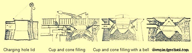
Gbr 4 Evolusi peralatan terbaik BF
Karena produksi BF meningkat karena banyak perbaikan desain, penghilangan produk cair (besi dan terak) menjadi masalah. Produksi arang BF telah meningkat selama periode tersebut dari satu ton menjadi 25 ton per hari. Tonase yang lebih tinggi ini tidak dapat ditangani dengan dua gips per hari melalui satu parit di depan lubang keran. Ukuran bangunan rumah cor meningkat menjadi sekitar 12 m lebar dan panjang 21 m. Rumah cor berisi area terpisah untuk pengecoran besi dan pembuangan terak. Sisi untuk pembuangan besi terdiri dari parit besar yang disebut palung yang miring ke bawah dari depan tungku ke lantai rumah cor yang diisi pasir. Itu kemudian tumpah ke dua sistem pelari. Runner utama pada setiap sistem berjalan paralel dengan panjang cast house. Saat pelari ini meluncur menuruni bukit, serangkaian bendungan dibuat secara berkala. Di sudut kanan sebelum setiap bendungan, pelari yang lebih kecil yang disebut 'sow' terbentuk di pasir. Kemudian dari babi ini ada banyak rongga yang disebut 'babi'. Nama-nama ini diterapkan karena sistem ini tampak seperti barisan anak babi yang sedang menyusui induknya (Gbr. 5). Ada beberapa baris paralel babi dan babi yang dihasilkan dengan mendorong bentuk kayu berbentuk D di pasir lembab di lantai rumah cor. Selama gips, karena setiap induk babi dan babinya diisi dengan besi cair, bendungan pasir pada pelari utama dirobohkan dengan sebatang dan logam cair mengalir menuruni bukit ke induk babi dan tempat tidur babi berikutnya. Ada dua sistem lengkap yang memungkinkan BF dilemparkan lebih sering. Saat satu sisi diisi dengan besi cair, di sisi lain babi-babinya disingkirkan dan tempat tidurnya diperbaiki.
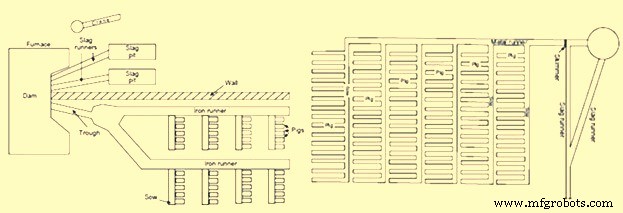
Gbr 5 Tempat tidur babi di rumah gips
Sisi lain dari rumah cor digunakan untuk menghilangkan terak. Terak terus-menerus mengalir di depan bendungan menuruni pelari terak dan masuk ke lubang terak. Bendungan terak di bagian depan BF dibagi menjadi dua bagian dengan masing-masing bagian memberi makan pelari terak dan lubang terak yang terpisah. Lubang terak adalah depresi besar di pasir dengan pegunungan di bagian bawah. Punggungan ini bertindak sebagai titik patah ketika tiba waktunya untuk menghilangkan terak yang mengeras. Di beberapa rumah tuang, derek kayu tipe jib digunakan untuk mengangkat potongan besar terak. Jika operator rumah cor melihat lapisan terak menjadi terlalu tebal, mereka biasanya menempatkan batang di tengah terak cair. Kemudian ketika terak mendingin di sekitar bar, tali atau rantai dapat dililitkan di sekelilingnya dan potongan-potongan besar terak diangkat oleh derek. Untuk pembuangan terak, ada juga dua sistem terak lengkap sehingga saat satu digunakan, yang lain dapat dibersihkan dan disiapkan.
Asal kata 'casting' dipahami berasal dari persepsi bahwa besi cair 'dikeluarkan' dari tungku. Operasi pengecoran terdiri dari dua bagian. Pada bagian pertama, ketika terak cair terbentuk di BF, terak akan mengapung di atas besi cair sampai mencapai tingkat yang cukup tinggi untuk mengalir antara timp dan bendungan ke dalam pelari terak dan ke lubang. Bagian kedua dari pengecoran adalah pemindahan besi cair dari perapian tungku. Ini dimulai dengan mematikan ledakan dan kemudian mengarahkan batang runcing ke lubang keran dengan palu godam. Besi cair mengalir melalui palung ke setiap induk babi yang berurutan dan babi-babinya. Ketika cairan besi berhenti mengalir, lubang keran ditutup secara manual dengan campuran lembab pasir dan fireclay atau pasir dan batu bara. Ledakan itu kemudian dikembalikan ke tungku.
Setelah pengecoran, operator rumah cor mengeluarkan besi yang dipadatkan dari tempat tidur babi. Ketika babi-babi itu cukup dingin untuk ditangani, mereka dikirim untuk dikirim. Siklus ini diulang enam kali per hari, dengan 4-6 ton yang diproduksi di setiap pengecoran. Pig iron yang dihasilkan diklasifikasikan ke dalam kelas yang berbeda. Besi arang memiliki nilai belerang rendah yang menghasilkan besi tuang abu-abu yang keras yang digunakan untuk memproduksi rel dan roda gerbong yang diperlukan untuk mendukung perluasan rel pada tahun 1800-an.
BF arang dihentikan pada akhir 1800-an, karena biaya produksinya tidak lagi dapat memenuhi persaingan yang datang dari praktik pembuatan besi berbasis mineral.
Pembuatan besi berdasarkan bahan bakar mineral
Karena menipisnya hutan perawan yang diperlukan untuk mempertahankan pembuatan besi arang, menjadi perlu untuk mencari sumber bahan bakar alternatif. Bahan bakar alternatif ini datang dalam bentuk batubara bituminous, batubara antrasit, kokas bahkan gambut. Perkembangan pembuatan coke dan besi antrasit paralel satu sama lain dan hidup berdampingan dengan produksi arang selama 1700-an dan 1800-an. Penggunaan batubara bituminous dan gambut terbatas dan tidak pernah menjadi bahan bakar utama pembuatan besi. Penggunaan bahan bakar mineral untuk pembuatan besi dimulai dari Inggris Raya, sejak deforestasi akibat produksi arang pertama kali terjadi di sana.
Pada tahun 1708, Abraham Darby menyewa BF arang kecil di Shropshire dan pada tahun 1709 dia memproduksi kokas. Dari tahun 1709 hingga 1718, kokas dicampur dengan arang dalam proporsi yang meningkat di tungku ini dan pada tahun 1718 BF menggunakan 100% kokas. Hingga 1750, tiga BF yang menggunakan coke secara teratur milik keluarga Darby. Penggunaan kokas menyebar selama periode 1750 hingga 1771, dengan total 27 BF menggunakan kokas untuk produksi besi. The use of coke increased the production of iron since it was stronger than charcoal. It could support the weight of more raw materials and thus the size of BF could be increased. Coke also improved permeability in the BF, allowing a larger volume of wind to pass through the furnace. This larger volume of compressed air was provided by the steam engine and blowing cylinders.
The use of coke in continental Europe spread slowly. Coke was used in Le Creussot, France in 1785, Gewitz, Silesia in 1796, Seraing, Belgium in 1826, Mulheim, Germany in 1849, Donete, Russia in 1871 and Bilbao, Spain in 1880. In North America, the first use of 100 % coke as the fuel was in 1835 at Huntington, Pennsylvania. However, since 1797, coke was mixed with other fuels in BFs of US.
The efficient use of coke and anthracite in producing iron was accelerated not only by the use of steam-driven blowing equipment but also by the invention of preheating of the air being blown in the BF. In the beginning of the 19th century, it was believed that use of cold blast improved both the quantity and quality of pig iron since it was observed that the production of the BFs was more in winter months and it was erroneously concluded that the lower blast temperature was the reason. But the BF performance improved during the winter months due to the fact that the air was having lower humidity so that more combustion of fuel was supported by a given volume of air blown into the furnace.
In 1828, James Neilson patented his invention of supplying preheated air blast to the tuyeres. The heating equipment was a simple wrought iron box having dimensions 1.2 m x 0.9 m x 0.6 m. This wrought iron box was externally heated. The maximum blast temperature which could be attained with this box was 93 deg C and one box was needed for each tuyere. In 1832, Neilson improved his invention by constructing a larger oven by joined flanges, formed a continuous length of 30 m and provided a heating surface of 22.3 sq m. This oven, which was fired with solid fuel, produced a hot blast temperature of 140 deg C. Since this invention, continuous modification and improvement in the hot blast ovens were made and by 1831, Dixon developed a taller oven with U-shaped pipes that supplied hot blast at 315 deg C. By 1840, about 55 % of pig iron at Great Britain was produced with hot blast.
With the increase in the hot blast temperature, there was decrease in the quantity of fuel needed and increase in the BF production. However the hot blast equipment needed a lot of maintenance. The cast iron pipes supported within a brick oven had different expansion characteristics, which resulted in several cracked pipes. Another issue was that the delivery equipment used for the cold blast, which consisted of solid tuyeres and flexible leather joints between pipes, could not withstand the high temperatures. Another issue with the original hot blast systems was the increased cost of solid fuel to heat the ovens. These issues helped further improvements in hot blast equipment. First, solid fuel used for heating was replaced with BF gas. Initially primitive heat exchanger type hot blast equipment was built on top of the BF and simply used the waste heat to preheat the cold blast running through the cast iron pipes. Then the BF gas from the furnace top was conveyed to the hot blast oven where it was burned to generate heat. This type of hot blast oven became quite complex with numerous rows of vertical pipes. The issue of cracking of the cast iron pipes was tackled by eliminating the pipes and using refractory. For using this method, 2 to 4 stoves were installed for each BF. As one stove was being heated by the burning the BF gas, another was being drained of its heat by heating of the cold blast. In 1854, the Cambria Iron Works was the first plant in the US to use regenerative stoves. The stoves were constructed of iron shells, internally lined with refractory and containing refractories with multiple passages for the blast. A typical stove of this design had 186 to 232 sq m of heating surface. These stoves were representative of those produced by Cowper and Whitwell in 1857. The Whitwell stoves erected in 1875 were 6.7 m in diameter, 9.1 m high and had a total heat surface of 8546 sq m. These were the first stoves to use hexagonal refractory checkers, cast iron checker supports, and a semi elliptical combustion chamber to improve distribution of gas through the checkers. These stoves could supply hot blast to the BF with temperatures of 454 deg C to 566 deg C. This stove design has remained basically the same till date with minor modifications in refractory type, checker shape and stove size.
The other improvement in equipment required by the use of hot blast was the design of the tuyeres and the tuyere stock. The solid cast iron or cast copper tuyeres used on cold blast furnaces were replaced by water cooled tuyeres which were hollow, conical shaped castings which had water circulating through their interior. The pipes from the blowing engines to the tuyeres, which were jointed with leather on cold blast furnaces, were redesigned with metal-to-metal seats. As hot blast temperatures increased the inside of these blast mains and tuyere stocks were lined with refractory, which required an overall increase in size.
The use of hot blast was applied to both coke and anthracite furnaces. As blast pressure increased with new blowing engines, it was found that anthracite could be charged with charcoal to improve the BF productivity. During 1986 the first attempt was made to use anthracite in a cold blast furnace in eastern France. This attempt failed since the ignited anthracite broke up into small pieces and blocked the blast from entering the BF. The evolution of coke iron making and anthracite iron making paralleled each other in the US during the 1800s. In 1826, a small BF was erected in Pennsylvania to operate exclusively on anthracite coal. This practice was unsuccessful both there as well as at other places in the US. During 1833, Dr. Frederick Geissenhainer successfully used hot blast in experiments to smelt iron with anthracite coal. In 1836 the Valley furnace in Pennsylvania used 100 % anthracite and in 1837, George Crane produced 36 tons of anthracite iron per week from one of his BFs at South Wales. David Thomas was the most successful iron maker in using the anthracite in the BF. In 1838 he came to the US and built the Catasauqua BF in 1840 (Fig 6). The furnace was 10.7 m square at the base with 3.6 m bosh and a height of 13.7 m. The hot blast stoves, fired with coal, were capable of heating the blast to 315 deg C. Since this BF successfully produced 50 tons of good foundry iron per week, the furnace was used as a model for the construction of blast furnaces built for using anthracite as a fuel. By 1856 there were 121 anthracite furnaces in operation in the US.
Other fuels were also tried for iron making in the BF. These were peat and bituminous coal. Peat BFs were similar to charcoal furnaces and typically were no higher than 6.7 m. Because the peat was physically weak, the use of these furnaces was located near to the peat deposits and they never played a major role in iron making evolution. Bituminous coal had been used to supplement charcoal prior to the introduction of hot blast. In the 1830s, splint coal was used in Scottish hot blast furnaces. In 1856, there were 6 BFs in Pennsylvania and 13 BFs in Ohio using bituminous coal. The bituminous coal era of iron making was essentially finished by 1895. This method of iron making never became a major force since the coal broke up into small pieces as the BFs were made larger and used higher blast pressure. With coke being the strongest and most available fuel, the evolution of 100 % coke furnaces continued. However there were initial setbacks probably due to low strength coke. By the 1840s coke quality had improved through the use of beehive ovens. In 1867, the ‘Monster’ blast furnace was built at Norton, England. This coke furnace was 25.9 m high, 7.6 m across the bosh and had a working volume of 735 cum. An example of a large coke furnace in the US in 1884 was the Etna furnace located near Pittsburgh. This furnace was 21.3 m high, 6.1 m in diameter at the bosh, 3.4 m in diameter at the hearth and had seven 7 inch (178 mm) tuyeres, three Whitwell stoves and three blowing cylinders that were 2.1 m in diameter. This BF produced 115 tons/day in 1881, 161 tons/day in 1882 and 182 tons/day in 1883. The coke furnace design at this time was very similar to the anthracite furnaces of the same era (Fig 6).
Further evolution of coke blast furnace
The evolution of BFs using 100 % coke continued with major improvements being made between 1872 and 1913. Several technological improvements were made which were centered on the hard-driving BF practice of using more powerful blowing engines, higher blast temperatures, bigger furnaces, better charging equipment, improved raw material preparation and production of clean BF gas.
Blowing equipment design and capacity was a major step to higher production in the hard-driving BFs. Blowing cylinders were replaced with large steam reciprocating blowing engines capable of providing a greater volume of blast air at a significantly higher blast pressure. These blowing engines were of the walking beam, steam condensing type. The steam cylinder’s piston rod was connected to a gallows beam and then by a crank to a heavy, large diameter flywheel. The blowing cylinder’s piston rod was connected to the other end of the gallows beam and each stroke of the steam cylinder provided a corresponding stroke of the blowing cylinder. Cold blast pipes were fitted to each end of the vertically positioned blowing cylinder so that air was compressed on both directions of the stroke. The flywheel provided momentum for the return stroke of the steam cylinder. The air that was compressed in this manner left the cold blast pipes and entered the cold blast main which connected to the hot blast stoves. Prior to this type of blowing engine the normal blast volume was 210 cum/min at a blast pressure of 0.28 kg/sq cm. This blowing engine could produce 456 cum/min at a blast pressure of 0.64 kg/sq cm. Then in 1910, the final major step in blowing engine improvement was implemented in the form of a turbo-blower. The first turbo-blower was installed for the BF of the Empire Steel Co. in New Jersey and was capable of delivering 636 cum/min of air blast. This turbo- blower was the direct ancestor of the modern turbo-blower which can deliver up to 7500 cum/min of blast volume at 4.00 kg/sq cm of blast pressure.
Another major improvement in high productivity BFs was to increase the charging capacity. In the 1870s the BFs were equipped with water driven elevators. In 1883, the first skip hoists were installed. Skips have become larger and faster into the 20th century and existed as both buckets and cars mounted on wheels. In the early 1960s some skip charging systems were replaced with large conveyor belts.
The improvements in furnace charging capacity also included automatic coke charging systems, scale cars in the stock house, two bell tops and the rotating distributor (Fig 6). Automatic stock line measurement was invented in 1901 by David Baker. In 1903, JE Johnson also began to measure top gas temperature and its analysis.
By 1850 as the furnace size increased, the furnace top could be closed. A single bell and hopper arrangement could be used for charging the furnace that kept the top of the furnace closed and sealed. The single bell and hopper system permitted large quantity of gas to escape every time the bell was opened. Soon a second bell and hopper was added above the first so that a gas tight space could be provided between the two bells to prevent the blast furnace gas escaping when the small bell was opened. The upper bell and hopper did not have to be as large as the lower one because several charges could be deposited through it on the lower bell and the upper bell could be closed before the lower bell was opened for dumping the charges in the furnace
Attempts to improve burden distribution occurred in the early 1990s with the McKee rotating top. After each skip of material was charged onto the small bell, the small bell hopper was rotated 60 deg, 180 deg, 240 deg, 300 deg, or 0 deg. This prevented a peak of raw material directly below the skip bridge which had resulted in uneven gas distribution and uneven lining wear. The next attempt to improve burden distribution was done in Germany in the late 1960s. This was accomplished by installing movable panels at the throat of the BF that could be set at different angles for ore or coke. This movable armour has been installed on large numbers of BFs.
The two bell system continued to be the only charging system for the blast furnaces around the world till S.A. Paul Wurth in Luxembourg, developed bell less top (BLT) charging system and the first successful industrial application of BLT charging system was in 1972. This equipment used air tight material hoppers that fed a rotating raw material delivery chute which could be set at numerous angles during the hopper discharge into the furnace. The result was the almost unlimited placement of each material anywhere on the burden surface which allowed the operator to achieve maximum fuel efficiency.
The BLT charging system took over from two bell charging system since it provided a number of advantages to BF operators. During 2003, Siemens VAI introduced Gimbal concept of charging.
Another attempt in the direction of the continuous improvement of the BFs for increasing the production was towards improvements in the cleaning of BF gas. As blast volume and pressure increased at the tuyeres, the velocity and volume of gas leaving the BF top also increased. More flue dust was then carried by this waste gas and if it was not removed, it began to plug up stove checkers which subsequently restricted blast volumes to the furnace. The first step in gas cleaning was the introduction of the dust catcher in the 1880s. With the introduction of the soft iron ores in 1892, the dry-type dust catcher was not sufficient. In 1909, Ambrose N. Diehl introduced a wet gas cleaning system. It consisted of a series of nine high-pressure spray towers and a set of four rotary washers. From 1914 to 1924, several types of tower washers equipped with multiple banks of sprays and baffles were tried at various furnaces. Gas disintegrators which contained high speed rotary drums were also tested in 1907. In 1929 electrostatic precipitators were used successfully at South Works of U.S. Steel. Today, combinations of tower-type gas washers, Venturi scrubbers and mist eliminators are the most common types of gas cleaning equipment.
The newest wet gas cleaning equipment is an annular gap scrubber which cleans the gas as well as controls top pressure. The final result of all these gas cleaning improvements was a decrease in stove checker brick hole diameter with an increase in stove size because plugging with dirt had been virtually eliminated. The resulting increase in stove heating surfaces has ultimately allowed modern stoves to deliver up to 1270 deg C hot blast temperature. The associated top pressure control allowed by modern gas cleaning equipment has resulted in furnace top pressures up to 2.3 kg/sq cm. This higher top pressure in turn increases the density of gases, decreases gas velocity and increases gas retention time in the furnace, yielding better gas-solid reactions, improved reducing gas utilization and lower fuel rates.
Recently, on the newly built and reconstructed BFs, particularly in China, dry cleaning of BF gas by bag filters has found the wide application. Dry cleaning of gas has several advantages over wet gas cleaning using scrubbers and Venturi tubes.
The quest for higher production rates in the late 1870s and onwards forced changes in the size of the furnace size and its configurations. In the 1870s, the furnaces were 22.9 m high. In 1880, the BF size increased to 24.7 m high, 6.1 m bosh diameter and 3.4 m hearth diameter. It produced 120 tons/day with a 1574 kg/ton coke rate. Just ten years later, in 1890, BF was constructed with a stack 28.0 m high and with 6.7 m bosh. It produced 325 tons/day. Then in another 10 years, in 1901, BF was started with similar stack and bosh dimensions as earlier furnace but the hearth diameter was increased to 4.4 m. This furnace produced 463 tons/day at 1113 kg/ton coke rate. The other subtle change with these size increases was the lowering of the bosh/stack bend line and the steepening of the bosh angle. This change was detrimental as the furnaces saw poor burden descent and slipping with these bosh angles. To eliminate these problems, the hearth diameter of these size furnaces was increased up to 6.7 m in 1927. This bigger hearth furnace produced 880 tons/day at a coke rate of 922 kg/ton. The first 1000 ton/day furnace was commissioned in 1929. This furnace was equipped with a hearth diameter of 7.6 m. In 1955, Great Lakes’ A furnace was the largest in the world with a 9.2 m hearth and 24 tuyeres. The next leap in blast furnace size increase occurred during the 1960s as Japan rebuilt their outdated steel plants. Today, furnaces with 15 m hearth diameter, 40 tuyeres and four to five tap holes, are common in Europe and Asia.
Along with the larger furnaces, higher blast temperatures and increasing driving rates, came the need for better BF refractory lining and cooling systems. In the 1880s a high duty fireclay brick with around 40 % alumina and 46 % silica was typical. However, C refractories were used in German BFs since 1886.
While refractory technology was relatively unknown at this time, methods to cool the lining seemed to be the answer to the wear problem. Beginning about 1880, there were simultaneous developments in efforts to maintain furnace linings by means of pipe coils around the bosh or by cooling plates embedded in the brick. One of the first uses of a bronze bosh plate is believed to be an installation made by Julian Kennedy at one of about 1890. An early reference to the use of water-cooled hearth jackets is on the furnace was in 1882. At this time, cooling of the hearth sidewalls and bosh was the concern and stack cooling was not felt to be necessary.
Fritz W Lurman, a well-known blast furnace man of the time opined in 1892 that ‘irrespective of the use of so called refractory materials, the best means of maintaining the walls of the blast furnace is with cooling water’. Coolers with water circulating in them are installed between the shell of the blast furnace and the refractory lining in the upper part of the furnace to protect these components from heat radiation. In addition to having its own coolers, the part of the shell adjacent to the hearth and the bottom of the furnace is also cooled in some furnaces on the outside by water sprays.
Function of blast furnace cooling system is to cool the furnace shell and prevent from the overheating and subsequent burn through. Cooling system removes the excess heat generated in the blast furnace which is otherwise loaded on the shell. Cooling system thus prevent the increase of the shell and lining temperature. Various methods exist for cooling of the shell for the blast furnace. In earlier times, cooling boxes of different size, number and design were used for transferring heat of the furnace to a cooling medium in conjunction with external cooling (spray cooling, double shell). Blast furnaces with cast iron cooling staves are operating since mid-1900s. Cast iron stave cooling was originally a Soviet discovery from where it travelled initially to India and Japan. By 1970s, cast iron cooling staves have attained world-wide acceptance. Since the introduction of these cast iron stave coolers, the development work of blast furnace cooling got accelerated and today a wide variety of coolers are available for the internal cooling of the furnace shell to suit extreme condition of stress in a modern large high performance blast furnace.
The higher charging rates were also wearing out the throat of the furnace faster. In 1872, iron or steel armour was built into the brickwork of the furnace throat at a furnace. Since that time, various types of armour have been used in the stock line area.
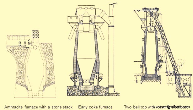
Fig 6 Early blast furnaces
The first important developments in brick making technology did not occur until the 1900s. In 1917, the first machine-made brick was introduced with its resulting increase in density and strength. In 1935, vacuum pressed bricks further improved brick quality. In 1939, super-duty alumina brick containing up to 60 % alumina was first available. In the 1930s, carbon blocks were used in German furnace hearths. Today many varieties of alumina, carbon, and silicon carbide refractories are available for BF lining. The improvements in furnace cooling and lining have increased typical campaign lengths from two years in the 1880s to more than ten years in the 1990s. Today campaign life of BFs has further increased to 20 years.
Another area of the BF which was forced to change with increased production was the casting operation. The old style tymp and dam open front of the furnace was no longer adequate. In 1867, the Lurman front was patented to eliminate the tymp and dam. It consisted of a cast iron panel which was water cooled and had separate openings for iron removal (still known as a tap hole) and for slag removal (known as the slag or cinder notch). This design was changed by the 1880s by rotating the slag notch 90 deg from the tap hole. Both the tap hole panel and slag notch panel were water cooled. By separating these two liquid tapping points, more room was available to set up the furnace for the increasing number of casts required at higher production rates. The area in front of the tap hole was completely available for pig beds while the slag pits were moved around to the side of the furnace (Fig 5). During normal operation, the slag notch was opened with a bar as the liquid slag level approached the tuyeres. The slag was flushed into pits or special slag cars. When the slag notch blew wind out of the opening, it was closed with a manual stopper. By tapping the slag off between iron taps, a greater volume of the hearth was available for liquid iron which resulted in larger cast tonnages. The iron casting process in the 1880s did not change much from previous operations but pig beds were bigger and in 1909 a slag skimmer was installed to skim the floating slag off of the iron as it flowed down the trough.
In 1896, the installation of a pig casting machine invented by EA Uehling finally brought about the complete elimination of the pig bed in the cast house. Next the open-top brick lined ladles were introduced. These ladles carried about 10 tons to 100 tons of hot metal and required the furnace and cast house to be elevated above ground level so the ladles could be placed under the cast house floor. Though the pig beds have got eliminated but troughs and runners remained and spouts going into the ladles were added to the cast house. In 1915, there was first use of the torpedo type ladles. These railroad mounted ladles carried 90 tons but were increased to 150 tons by 1925. Today, the iron ladle design is similar but capacities up to 400 tons are available. Open-type ladles mounted on rail cars are still used today.
Prior to 1890, the tap hole was opened with a bar and sledge hammer. Then in 1890 the first pneumatic rock drill was used. The tap hole was manually stopped with wind off the furnace until 1914 when HA Berg developed the remote controlled mud gun which pushed a clay plug into the furnace with a wind on. In 1906, the first oxygen lancing was used to melt skulls in the tap hole. Modern BFs have evolved to include remote controlled tap hole drills, hydraulic mud guns, cast house slag granulation units and iron tilting spouts to feed an unlimited number of iron ladles. BFs may also have from one to four tap holes and two to six slag pits depending on their size. Removing the bottleneck in the cast house allowed the first 1000 ton/day operation in 1929 and led to 1990s production levels of 12,000 ton/day.
A parallel line of improvement activities which rapidly evolved starting in the late 1800s was iron ore preparation. Iron ore used in iron making consists of many geological forms such as red hematite, specular hematite, magnetite, limonite, fossil ores, bog ores and carbonates. The metallic iron content of these ores ranges from approximately 30 % in the bog ores to 72 % in some hematites. All iron ores are mixed with other compounds in the earth which are undesirable in the smelting process. Beginning in the 1700s, iron ore was roasted with charcoal in open pits or enclosed kilns. The object of roasting or calcining was to liberate all volatile constituents, such as water, carbonic acid or bituminous substances, and to soften and crack the ores, making them more permeable to reducing gases. In the 1800s, iron ore screening was introduced to more closely size the ore for improved gas permeability inside the furnace. At first, hand screening equipment was used but, by the 1870s, steam-driven ore washers consisted of one or two drums that were perforated with holes or slots for the fine material to exit with the wash water while the final sized and washed ore exited the inside of the drum into a wheelbarrow or stockpile.
As iron production increased, the purest iron ores were depleted in many areas so lower grade ores had to be mined. These ores had undesirable impurities and methods to concentrate these ores to higher iron percentages were required. In 1880, Thomas A. Edison obtained a patent for an electromagnetic separator. A demonstration plant was built in Michigan and produced 893 tons of magnetic concentrate in 1889.
Pilot plants to pelletize taconite concentrates were built in 1948. By 1956, two commercial-scale taconite mining and processing operations were producing pellets. The first straight grate pellet machine was made in 1956 and the first grate-kiln pellet machine was put into operation in 1960. Pelletizing technology spread throughout the world from the US. The newest development in pelletizing was the introduction of raw limestone, dolomite or olivine into the pellet to improve its metallurgical properties which, in turn, improved BF productivity and fuel rates.
Iron ore agglomeration also took a separate route from pelletizing earlier in the 1900s. Sintering process originated in the nonferrous industry as a batch process in the late 19th century. Up to the 1950s, most sinter had a basicity ratio of less than 1.0. However, over the next fifteen years, it was realized that a basic sinter with a basicity ratio of more than 1.0 brought a pre-calcined flux source into the BF which resulted in a fuel rate savings.
One of the final technological improvements in iron making over the last 100 years has been tuyere level injectants. The first recorded use of injectant was in 1871 when there was a chilled hearth on the Morgan charcoal furnace. Because blast could not enter the tuyeres due to chilled material, a hole was punched through the furnace wall above the salamander and a large tuyere was installed. Coal oil was then forced under pressure into the tuyere from a pipe running from the top of the furnace. Six days and seven barrels of oil later the salamander had been melted and the furnace was running smoothly. In the first decade of the 1900s early tests with oxygen injection were made in the small BF in Belgium. The first large scale oxygen enriched blast was used in 1951. The benefits of pure oxygen injection are increased BF production due to increased fuel burning capacity and an ability to use more hydrocarbon tuyere injectants. The evolution of hydrocarbon injectant occurred in the 1940s and 1950s. In 1944, William L. Pogue submitted a patent for the use of coal injection. Then in 1953, natural gas injection was implemented. In the early 1960s, injection of oil and tar through lances was developed at numerous steel companies after substantial coke savings were proven by testing in an experimental BF in 1959. By 1967, a large number of the BFs were using some form of fuel (mostly pulverized coal) injection. Today, many BFs use fuel injectants 40 % to 45 % of the fuel rate. The final tuyere injectant, which evolved concurrently with fuel injection, was moisture injection. Historically, hot blast temperatures were limited as excessively high temperature combustion zones resulted in poor burden descent. The injection of moisture consumed coke more rapidly than air alone and produced a gas that was both richer in carbon monoxide and hydrogen and was less dense. These factors improved the rate of heat transfer between gases and solids and the rate of reduction of the burden in the furnace stack, which resulted in a smooth running furnace.
The combination of moisture injection, fuel injection and oxygen injection permitted the increase of hot blast temperature and the use of all of these tuyere level variables further improved productivity and reduced fuel rates in modern BFs.
Evolution of BF iron making as a science
Historically, iron making was more an art than a science. Early iron producers learned their trade through years of training from the previous generation. Many improvements in iron making practice were based on instinct or pure luck. However, by the mid-nineteenth century, science was creeping into the developments in iron smelting.
Charles Schinz of Germany, one of the earliest researchers of chemical and physical phenomena occurring inside a BF, attempted to make quantitative mass and energy balances of BF operation but he was severely limited by the lack of accurate thermodynamic data. He conducted laboratory experiments to determine heat capacity and heats of formation and was apparently the first to determine the reducibility of iron ore. He defined different zones of the BF and the major chemical reactions taking place in each zone. The results of his work were published in 1868.
Several principles which are recognized today were postulated by Sir Lothian Bell, during the late 1800s. He published a book in 1872 which is recognized as the first text book on BF iron making. In 1884, he was seemingly the first to document the function of the different slag components and their effect on melting temperature. He also observed that BF slags are complex structures and there is a range of slag compositions which results in its good fluid properties and desulfurizing capability. His most important contribution was his understanding of chemical reactions. He recognized the importance of CO and CO2, and was the first to start defining equilibrium in the Fe-O-C system. Further, Bell discussed preheating and pre-reduction of iron ores and the importance of the furnace stack where these reactions occurred. He also made carbon, oxygen and nitrogen balances of the BF operations and showed that some of the charged carbon was consumed in the stack by CO2 in the ‘solution loss’ reaction.
A contemporary of Bell was ML Gruner, a professor of metallurgy in France, further expanded Bell’s methods of determining BF heat balances by comparing many different furnace operations. He also believed that the minimum fuel rate for BFs would be achieved when solution loss was eliminated.
JE Johnson, Jr. was the first American scientist to explore the BF process and published two books on BF design and operation in the early 1900s. He applied the first and second laws of thermodynamics to iron making and explained how fuel rate was impacted by blast temperature. He postulated that there was a critical furnace temperature above which a minimum amount of heat is required. This minimum amount of heat he called ‘hearth heat’. In his book, published in 1913, Johnson produced a diagram showing chemical reactions and isotherms in the BF. The application of the critical temperature and hearth heat concepts further convinced furnace operators that the BF process was rational and predictable.
During the period from 1920 to 1930, the flow of solids and gases in the BF was studied extensively by a group of workers named PH Royster, SP Kinney, CC Furnas, and TL Joseph. This group was interested in physical and chemical phenomena occurring in BFs and in order to understand these phenomena they felt it was necessary to sample and probe operating furnaces. Their work started with a small experimental BF and spread to commercial furnaces. The results of their studies showed that the flow of gases and solids was not uniform across any horizontal plane in the BF and that improving gas-solid contact in the stack of the furnace could significantly increase the efficiency of the iron making process. Furnas and Joseph continued this work and determined that raw material size and reducibility was critical in gas-solid reactions. This important work led to the understanding of burden distribution and the optimization of iron ore sizing as it impacts both reducibility and permeability.
In 1962, R. Stephenson explained the role of solution loss. Previously, it had been thought the production of CO by reacting with CO2 and carbon was a waste of fuel. Stephenson pointed out that iron oxide reduction is a combination of indirect reduction and direct reduction and that indirect reduction followed by solution loss is direct reduction. Using these considerations to determine carbon rates for all combinations of these two reduction routes as a function of solution loss, results can be plotted on the ‘carbon-direct reduction diagram’. In the 1960s and early 1970s, the best applications of these BF theories were put into practice in Japan. Currently, the Japanese improvements have spread in the form of large, highly automated BFs to other places.
The theory and practice of iron smelting technology have come a long way in the last 4000 years. The transition from sponge iron produced in forges to liquid iron produced in BFs in the 1300s was the first major step in advancing iron making technology. Then came the change from cold blast, charcoal furnaces to hot blast, coke furnaces in the mid-1800s which brought iron making into the modern era. The better understanding of iron making reactions and improved equipment evolved into the hard-driving furnace operation centered in the 1880s to 1900s. Finally, the revolution in scientific applications to iron smelting, the installation of more sophisticated equipment, and the advent of electronically controlled systems has accelerated BF iron making into the current state as demonstrated by the operation of around 12,000 tons/day BFs with fuel rates less than 460 kg/ton.


