Menguasai Pengenalan dan Sintesis Ucapan pada Arduino Due
Komponen dan Perlengkapan
Komponen
Jumlah
Arduino Due
1
SparkFun Electret Microphone Breakout
1
SparkFun Mono Audio Amp Breakout
1
Speaker: 0.25W, 8 ohms
1
Breadboard (generic)
1
5 mm LED: Merah
3
Resistor 330 ohm
3
Kabel Jumper (generic)
1
Alat dan Mesin yang Diperlukan
Paku las (generic)
Aplikasi dan Layanan Online
BitVoicer Server 1.0
Tentang Proyek
Dalam proyek sebelumnya, saya menunjukkan cara mengontrol beberapa LED menggunakan papan Arduino dan BitVoicer Server. Dalam proyek ini, saya akan membuat hal-hal menjadi sedikit lebih rumit. Saya juga akan mensintesis ucapan menggunakan konverter digital-to-analog (DAC) Arduino DUE. Jika Anda tidak memiliki Arduino DUE, Anda dapat menggunakan papan Arduino lainnya, tetapi Anda akan membutuhkan DAC eksternal dan kode tambahan untuk mengoperasikan DAC (perpustakaan BVSSpeaker tidak akan membantu Anda dengan itu).
Dalam video di bawah ini, Anda dapat melihat bahwa saya juga membuat Arduino memutar lagu kecil dan memantulkan LED seolah-olah mereka adalah kunci piano. Maaf untuk keterampilan piano saya, tetapi itu yang terbaik yang bisa saya lakukan :) . LED sebenarnya berkedip dalam urutan dan waktu yang sama dengan kunci C, D, dan E yang sebenarnya, jadi jika Anda memiliki piano di sekitar Anda, Anda dapat mengikuti LED dan memutar lagu yang sama. Ini adalah jingle dari suatu pengedag lama (Mappin) yang bahkan tidak ada lagi.
Berikut adalah prosedur yang akan dieksekusi untuk mengubah perintah suara menjadi aktivitas LED dan ucapan yang disintesis:
1. Gelombang audio akan ditangkap dan diperkuat oleh papan Sparkfun Electret Breakout;
2. Sinyal yang diperkuat akan digitalkan dan disimpan di buffer pada Arduino menggunakan konverter analog-to-digital (ADC);
3. Sampel audio akan di-stream ke BitVoicer Server menggunakan port serial Arduino;
4. BitVoicer Server akan memproses stream audio dan mengenali ucapan yang terkandung di dalamnya;
5. Ucapan yang dikenali akan dipetakan ke perintah yang telah ditentukan yang akan dikembalikan ke Arduino. Jika salah satu perintah terdiri dari sintesis ucapan, BitVoicer Server akan menyiapkan stream audio dan mengirimkannya ke Arduino;
6. Arduino akan mengidentifikasi perintah dan melakukan tindakan yang sesuai. Jika stream audio diterima, ia akan diantrekan ke dalam kelas BVSSpeaker dan diputar menggunakan DAC dan DMA DUE.
7. SparkFun Mono Audio Amp akan memperkuat sinyal DAC sehingga dapat menggerakkan speaker 8 Ohm.
Daftar Bahan:
Arduino DUE: ~U$ 50.00
Sparkfun Electret Microphone Breakout: U$ 7.95
SparkFun Mono Audio Amp Breakout: U$ 7.95
BitVoicer Server 1.0: U$ 9.90
Speaker 8 Ohm: ~U$ 2.00
Breadboard: ~U$ 10.00
3 x LED: ~U$ 1.00
3 x Resistor 330 Ohm: ~U$ 0.75
Kabel Jumper: ~U$ 0.50
LANGKAH 1: Penyambungan
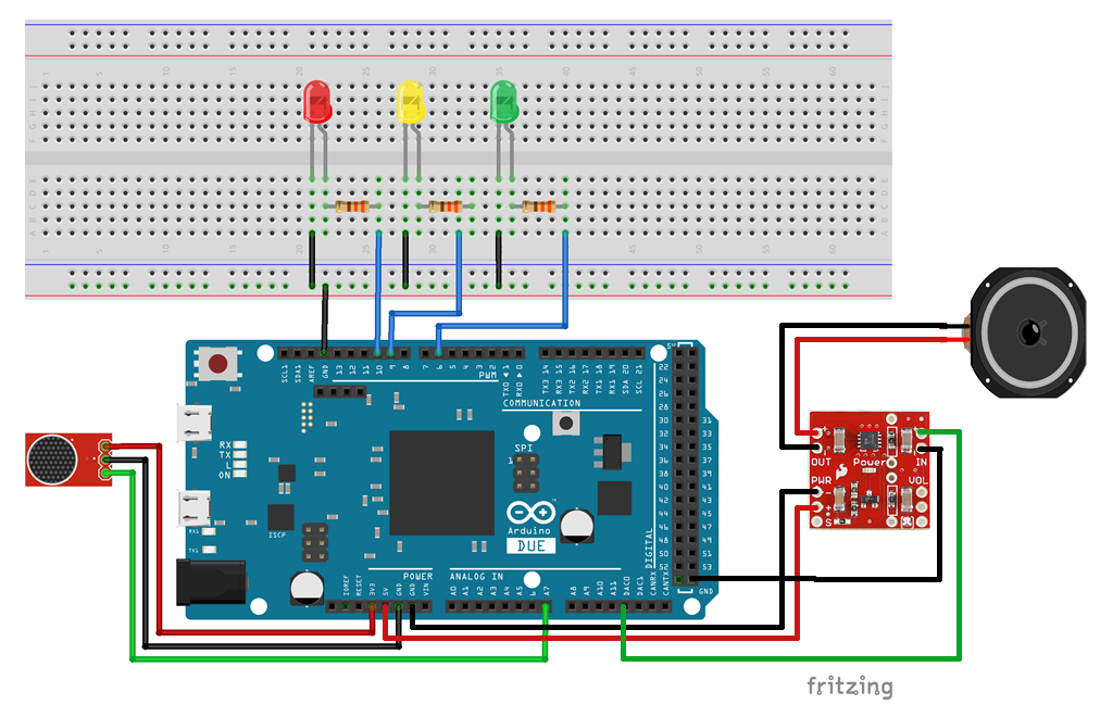
Langkah pertama adalah menyambungkan Arduino dan breadboard dengan komponse seperti yang ditunjukkan dalam gambar di bawah ini. Saya harus menempatkan karet kecil di bawah speaker karena speaker getar banyak dan tanpa karet kualitas audio sangat terpengaruh.
Di sini kita memiliki perbedaan kecil namun penting dari proyek saya sebelumnya. Sebagian besar papan Arduino berjalan pada 5V, tetapi DUE berjalan pada 3.3V. Karena saya mendapatkan hasil yang lebih baik menjalankan Sparkfun Electret Breakout pada 3.3V, saya merekomendasikan Anda menambahkan jumper antara pin 3.3V dan pin AREF JIKA Anda menggunakan papan Arduino 5V. DUE sudah menggunakan referensi analog 3.3V jadi Anda tidak memerlukan jumper ke pin AREF. Faktanya, pin AREF pada DUE terhubung ke mikrokontroler melalui jembatan resistor. Untuk menggunakan pin AREF, resistor BR1 harus dicabut dari PCB.
LANGKAH 2: Mengunggah Kode ke Arduino
Sekarang Anda harus mengunggah kode di bawah ini ke Arduino Anda. Untuk kenyamanan, sketsa Arduino juga tersedia di bagian Lampiran di bawah postingan ini. Sebelum Anda mengunggah kode, Anda harus menginstal perpustakaan BitVoicer Server ke Arduino IDE dengan benar (Mengimpor Perpustakaan .zip).
Sketsa Arduino: BVS_Demo2.ino
Sketsa ini memiliki tujuh bagian utama:
Referensi perpustakaan dan deklarasi variabel: Empat baris pertama mencakup referensi ke perpustakaan BVSP, BVSMic, BVSSpeaker dan DAC. Perpustakaan ini disediakan oleh BitSophia dan dapat ditemukan di folder instalasi BitVoicer Server. Perpustakaan DAC disertakan secara otomatis saat Anda menambahkan referensi ke perpustakaan BVSSpeaker. Baris lainnya mendeklarasikan konstanta dan variabel yang digunakan selama sketsa. Kelas BVSP digunakan untuk berkomunikasi dengan BitVoicer Server, kelas BVSMic digunakan untuk menangkap dan menyimpan sampel audio dan kelas BVSSpeaker digunakan untuk mereproduksi audio menggunakan DAC DUE.
Fungsi Setup: Fungsi ini melakukan tindakan berikut: mengatur mode pin dan kondisi awalnya; memulai komunikasi serial; dan memulai kelas BVSP, BVSMic dan BVSSpeaker. Ini juga menyetel "penangan peristiwa" (sebenarnya adalah pointer fungsi) untuk peristiwa frameReceived, modeChanged dan streamReceived dari kelas BVSP.
Fungsi Loop: Fungsi ini melakukan lima tindakan penting: meminta informasi status ke server (fungsi keepAlive()); memeriksa apakah server telah mengirim data apa pun dan memproses data yang diterima (fungsi receive()); mengontrol perekaman dan pengiriman stream audio (fungsi isSREAvailable(), startRecording(), stopRecording() dan sendStream()); memutar sampel audio yang diantrekan ke dalam kelas BVSSpeaker (fungsi play()); dan memanggil fungsi playNextLEDNote() yang mengontrol cara LED harus berkedip setelah perintah playLEDNotes diterima.
Fungsi BVSP_frameReceived: Fungsi ini dipanggil setiap kali fungsi receive() mengidentifikasi bahwa satu frame lengkap telah diterima. Di sini saya menjalankan perintah yang dikirim dari BitVoicer Server. Perintah yang mengontrol LED berisi 2 byte. Byte pertama menunjukkan pin dan byte kedua menunjukkan nilai pin. Saya menggunakan fungsi analogWrite() untuk menetapkan nilai yang sesuai ke pin. Saya juga memeriksa apakah perintah playLEDNotes, yang bertipe Byte, telah diterima. Jika telah diterima, saya mengatur playLEDNotes menjadi true dan menandai waktu saat ini. Waktu ini akan digunakan oleh fungsi playNextLEDNote untuk sinkronkan LED dengan lagu.
Fungsi BVSP_modeChanged: Fungsi ini dipanggil setiap kali fungsi receive() mengidentifikasi perubahan mode di arah keluar (Server --> Arduino). WOW!!! Itu apa?! BitVoicer Server dapat mengirim data bertingkat atau stream audio ke Arduino. Sebelum komunikasi beralih dari satu mode ke mode lain, BitVoicer Server mengirim sinyal. Kelas BVSP mengidentifikasi sinyal ini dan memunculkan peristiwa modeChanged. Dalam fungsi BVSP_modeChanged, jika saya mendeteksi komunikasi beralih dari mode stream ke mode bertingkat, saya tahu audio telah selesai jadi saya dapat memberitahu kelas BVSSpeaker untuk berhenti memutar sampel audio.
Fungsi BVSP_streamReceived: Fungsi ini dipanggil setiap kali fungsi receive() mengidentifikasi bahwa sampel audio telah diterima. Saya cukup mengambil sampel dan mengantrikannya ke dalam kelas BVSSpeaker sehingga fungsi play() dapat mereproduksinya.
Fungsi playNextLEDNote: Fungsi ini hanya berjalan jika fungsi BVSP_frameReceived mengidentifikasi perintah playLEDNotes. Ini mengontrol dan menyinkronkan LED dengan audio yang dikirim dari BitVoicer Server. Untuk menyinkronkan LED dengan audio dan mengetahui waktu yang tepat, saya menggunakan Sonic Visualizer. Perangkat lunak gratis ini memungkinkan saya untuk melihat gelombang audio sehingga saya dapat dengan mudah mengetahui kapan kunci piano ditekan. Ini juga menunjukkan garis waktu dan itulah cara saya mendapatkan milidetik yang digunakan dalam fungsi ini. Ini terdengar seperti trik konyol dan memang demikian. Saya pikir akan mungkin untuk menganalisis stream audio dan menyalakan LED yang sesuai, tetapi itu di luar kemampuan saya.
LANGKAH 3: Mengimpor Objek Solusi BitVoicer Server
Sekarang Anda harus menyiapkan BitVoicer Server untuk bekerja dengan Arduino. BitVoicer Server memiliki empat objek solusi utama: Lokasi, Perangkat, Data Biner dan Skema Suara.
Lokasi mewakili lokasi fisik di mana suatu perangkat dipasang. Dalam kasus saya, saya membuat lokasi bernama Home.
Perangkat adalah klien BitVoicer Server. Saya membuat perangkat Mixed, memberinya nama ArduinoDUE dan memasukkan pengaturan komunikasi. PENTING: meskipun Arduino DUE memiliki sejumlah kecil memori untuk menyimpan semua sampel audio yang akan di-stream oleh BitVoicer Server. Jika Anda tidak membatasi bandwidth, Anda akan membutuhkan buffer yang jauh lebih besar untuk menyimpan audio. Saya mengalami beberapa buffer overflow karena alasan ini jadi saya harus membatasi Laju Data dalam pengaturan komunikasi ke 8000 sampel per detik.
Data Biner adalah tipe perintah yang dapat dikirim oleh BitVoicer Server ke perangkat klien. Mereka sebenarnya adalah array byte yang dapat Anda hubungkan ke perintah. Saat BitVoicer Server mengenali ucapan yang terkait dengan perintah tersebut, ia mengirim array byte ke perangkat target. Saya membuat satu objek Data Biner untuk setiap nilai pin dan menamai mereka ArduinoDUEGreenLedOn, ArduinoDUEGreenLedOff dan seterusnya. Saya akhirnya memiliki 18 objek Data Biner dalam solusi saya, jadi saya menyarankan Anda untuk mengunduh dan mengimpor objek dari berkas VoiceSchema.sof di bawah ini.
Skema Suara adalah di mana semuanya berkumpul. Mereka menentukan kalimat apa yang harus dikenali dan perintah apa yang harus dijalankan. Untuk setiap kalimat, Anda dapat menentukan sebanyak mungkin perintah yang Anda butuhkan dan urutan eksekusi. Anda juga dapat menentukan jeda di antara perintah. Itulah cara saya mengelola urutan tindakan yang Anda lihat dalam video.
Salah satu kalimat dalam Skema Suara saya adalah "play a little song." Kalimat ini berisi dua perintah. Perintah pertama mengirim byte yang menunjukkan bahwa perintah berikutnya akan menjadi stream audio. Arduino kemudian mulai "memutar" LED saat audio ditransmisikan. Audio adalah jingle piano kecil yang saya cat sendiri dan tetapkan sebagai sumber audio dari perintah kedua. BitVoicer Server hanya mendukung audio PCM mono 8-bit (8000 sampel per detik) jadi jika Anda perlu mengonversi file audio ke format ini, saya merekomendasikan alat konversi online berikut: https://audio.online-convert.com/convert-to-wav.
Anda dapat mengimpor (Mengimpor Objek Solusi) semua objek solusi yang saya gunakan dalam proyek ini dari berkas di bawah ini. Satu berisi Perangkat DUE dan yang lain berisi Skema Suara dan Perintahnya.
Berkas Objek Solusi:
Device.sof
VoiceSchema.sof
LANGKAH 4: Kesimpulan
Nah, itulah! Anda dapat menyalakan semuanya dan melakukan hal-hal yang sama yang ditunjukkan dalam video.
Seperti yang saya lakukan dalam proyek saya sebelumnya, saya memulai pengenalan suara dengan mengaktifkan perangkat Arduino di BitVoicer Server Manager. Begitu dia diaktifkan, Arduino mengidentifikasi Mesin Pengenalan Suara yang tersedia dan mulai mem-stream audio ke BitVoicer Server. Namun, sekarang Anda melihat banyak aktivitas di LED Arduino RX saat audio di-stream dari BitVoicer Server ke Arduino.
Dalam proyek saya berikutnya, saya akan sedikit lebih ambisius. Saya akan menambahkan komunikasi WiFi ke satu Arduino dan mengontrol dua Arduino lainnya sekaligus dengan suara. Saya memikirkan suatu jenis permainan di antara mereka. Saran sangat dipersilakan!
Kode
Sketsa Arduino
Sketsa ArduinoArduino
#include <BVSP.h> #include <BVSMic.h> #include <BVSSpeaker.h> #include <DAC.h> // Defines the Arduino pin that will be used to capture audio #define BVSM_AUDIO_INPUT 7 // Defines the LED pins #define RED_LED_PIN 6 #define YELLOW_LED_PIN 9 #define GREEN_LED_PIN 10 // Defines the constants that will be passed as parameters to // the BVSP.begin function const unsigned long STATUS_REQUEST_TIMEOUT = 3000; const unsigned long STATUS_REQUEST_INTERVAL = 4000; // Defines the size of the mic audio buffer const int MIC_BUFFER_SIZE = 64; // Defines the size of the speaker audio buffer const int SPEAKER_BUFFER_SIZE = 128; // Defines the size of the receive buffer const int RECEIVE_BUFFER_SIZE = 2; // Initializes a new global instance of the BVSP class BVSP bvsp = BVSP(); // Initializes a new global instance of the BVSMic class BVSMic bvsm = BVSMic(); // Initializes a new global instance of the BVSSpeaker class BVSSpeaker bvss = BVSSpeaker(); // Creates a buffer that will be used to read recorded samples // from the BVSMic class byte micBuffer[MIC_BUFFER_SIZE]; // Creates a buffer that will be used to write audio samples // into the BVSSpeaker class byte speakerBuffer[SPEAKER_BUFFER_SIZE]; // Creates a buffer that will be used to read the commands sent // from BitVoicer Server. // Byte 0 = pin number // Byte 1 = pin value byte receiveBuffer[RECEIVE_BUFFER_SIZE]; // These variables are used to control when to play // "LED Notes". These notes will be played along with // the song streamed from BitVoicer Server. bool playLEDNotes = false; unsigned int playStartTime = 0; void setup() { // Sets up the pin modes pinMode(RED_LED_PIN, OUTPUT); pinMode(YELLOW_LED_PIN, OUTPUT); pinMode(GREEN_LED_PIN, OUTPUT); // Sets the initial state of all LEDs digitalWrite(RED_LED_PIN, LOW); digitalWrite(YELLOW_LED_PIN, LOW); digitalWrite(GREEN_LED_PIN, LOW); // Starts serial communication at 115200 bps Serial.begin(115200); // Sets the Arduino serial port that will be used for // communication, how long it will take before a status request // times out and how often status requests should be sent to // BitVoicer Server. bvsp.begin(Serial, STATUS_REQUEST_TIMEOUT, STATUS_REQUEST_INTERVAL); // Defines the function that will handle the frameReceived // event bvsp.frameReceived = BVSP_frameReceived; // Sets the function that will handle the modeChanged // event bvsp.modeChanged = BVSP_modeChanged; // Sets the function that will handle the streamReceived // event bvsp.streamReceived = BVSP_streamReceived; // Prepares the BVSMic class timer bvsm.begin(); // Sets the DAC that will be used by the BVSSpeaker class bvss.begin(DAC); } void loop() { // Checks if the status request interval has elapsed and if it // has, sends a status request to BitVoicer Server bvsp.keepAlive(); // Checks if there is data available at the serial port buffer // and processes its content according to the specifications // of the BitVoicer Server Protocol bvsp.receive(); // Checks if there is one SRE available. If there is one, // starts recording. if (bvsp.isSREAvailable()) { // If the BVSMic class is not recording, sets up the audio // input and starts recording if (!bvsm.isRecording) { bvsm.setAudioInput(BVSM_AUDIO_INPUT, DEFAULT); bvsm.startRecording(); } // Checks if the BVSMic class has available samples if (bvsm.available) { // Makes sure the inbound mode is STREAM_MODE before // transmitting the stream if (bvsp.inboundMode == FRAMED_MODE) bvsp.setInboundMode(STREAM_MODE); // Reads the audio samples from the BVSMic class int bytesRead = bvsm.read(micBuffer, MIC_BUFFER_SIZE); // Sends the audio stream to BitVoicer Server bvsp.sendStream(micBuffer, bytesRead); } } else { // No SRE is available. If the BVSMic class is recording, // stops it. if (bvsm.isRecording) bvsm.stopRecording(); } // Plays all audio samples available in the BVSSpeaker class // internal buffer. These samples are written in the // BVSP_streamReceived event handler. If no samples are // available in the internal buffer, nothing is played. bvss.play(); // If playLEDNotes has been set to true, // plays the "LED notes" along with the music. if (playLEDNotes) playNextLEDNote(); } // Handles the frameReceived event void BVSP_frameReceived(byte dataType, int payloadSize) { // Checks if the received frame contains binary data // 0x07 = Binary data (byte array) if (dataType == DATA_TYPE_BINARY) { // If 2 bytes were received, process the command. if (bvsp.getReceivedBytes(receiveBuffer, RECEIVE_BUFFER_SIZE) == RECEIVE_BUFFER_SIZE) { analogWrite(receiveBuffer[0], receiveBuffer[1]); } } // Checks if the received frame contains byte data type // 0x01 = Byte data type else if (dataType == DATA_TYPE_BYTE) { // If the received byte value is 255, sets playLEDNotes // and marks the current time. if (bvsp.getReceivedByte() == 255) { playLEDNotes = true; playStartTime = millis(); } } } // Handles the modeChanged event void BVSP_modeChanged() { // If the outboundMode (Server --> Device) has turned to // FRAMED_MODE, no audio stream is supposed to be received. // Tells the BVSSpeaker class to finish playing when its // internal buffer become empty. if (bvsp.outboundMode == FRAMED_MODE) bvss.finishPlaying(); } // Handles the streamReceived event void BVSP_streamReceived(int size) { // Gets the received stream from the BVSP class int bytesRead = bvsp.getReceivedStream(speakerBuffer, SPEAKER_BUFFER_SIZE); // Enqueues the received stream to play bvss.enqueue(speakerBuffer, bytesRead); } // Lights up the appropriate LED based on the time // the command to start playing LED notes was received. // The timings used here are syncronized with the music. void playNextLEDNote() { // Gets the elapsed time between playStartTime and the // current time. unsigned long elapsed = millis() - playStartTime; // Turns off all LEDs allLEDsOff(); // The last note has been played. // Turns off the last LED and stops playing LED notes. if (elapsed >= 11500) { analogWrite(RED_LED_PIN, 0); playLEDNotes = false; } else if (elapsed >= 9900) analogWrite(RED_LED_PIN, 255); // C note else if (elapsed >= 9370) analogWrite(RED_LED_PIN, 255); // C note else if (elapsed >= 8900) analogWrite(YELLOW_LED_PIN, 255); // D note else if (elapsed >= 8610) analogWrite(RED_LED_PIN, 255); // C note else if (elapsed >= 8230) analogWrite(YELLOW_LED_PIN, 255); // D note else if (elapsed >= 7970) analogWrite(YELLOW_LED_PIN, 255); // D note else if (elapsed >= 7470) analogWrite(RED_LED_PIN, 255); // C note else if (elapsed >= 6760) analogWrite(GREEN_LED_PIN, 255); // E note else if (elapsed >= 6350) analogWrite(RED_LED_PIN, 255); // C note else if (elapsed >= 5880) analogWrite(YELLOW_LED_PIN, 255); // D note else if (elapsed >= 5560) analogWrite(RED_LED_PIN, 255); // C note else if (elapsed >= 5180) analogWrite(YELLOW_LED_PIN, 255); // D note else if (elapsed >= 4890) analogWrite(YELLOW_LED_PIN, 255); // D note else if (elapsed >= 4420) analogWrite(RED_LED_PIN, 255); // C note else if (elapsed >= 3810) analogWrite(GREEN_LED_PIN, 255); // E note else if (elapsed >= 3420) analogWrite(RED_LED_PIN, 255); // C note else if (elapsed >= 2930) analogWrite(YELLOW_LED_PIN, 255); // D note else if (elapsed >= 2560) analogWrite(RED_LED_PIN, 255); // C note else if (elapsed >= 2200) analogWrite(YELLOW_LED_PIN, 255); // D note else if (elapsed >= 1930) analogWrite(YELLOW_LED_PIN, 255); // D note else if (elapsed >= 1470) analogWrite(RED_LED_PIN, 255); // C note else if (elapsed >= 1000) analogWrite(GREEN_LED_PIN, 255); // E note } // Turns off all LEDs. void allLEDsOff() { analogWrite(RED_LED_PIN, 0); analogWrite(YELLOW_LED_PIN, 0); analogWrite(GREEN_LED_PIN, 0); }