Penyertaan dalam Baja Cor Berkelanjutan dan Deteksinya
Pencantuman dalam Baja Cor Kontinu dan Deteksinya
Pengecoran baja secara terus-menerus adalah proses penting untuk produksi baja di seluruh dunia, karena keunggulan yang melekat pada penghematan energi, hasil tinggi, fleksibilitas operasi, dan kualitas produk cor yang kompetitif. Dengan penetapan pengecoran kontinu sebagai rute utama produksi baja, penekanan semakin difokuskan pada aspek peningkatan kualitas dan pengurangan biaya produksi baja melalui teknologi pengecoran kontinu. Salah satu persyaratan kualitas yang paling ketat saat ini adalah kebersihan baja. Kebersihan baja yang tinggi menuntut kontrol yang ketat terhadap inklusi non-logam atau sekadar inklusi selama proses pengecoran kontinu. Penyertaan yang tersisa dalam produk akhir dapat merusak sifat baja dan menurunkan kualitasnya.
Penghapusan inklusi dalam cetakan pengecoran kontinyu sulit karena baja cair menjadi padat dan inklusi memiliki sedikit kesempatan untuk mengapung keluar. Penghapusan inklusi dan distribusi akhir inklusi dalam produk baja sangat bergantung pada sifat inklusi, pengangkutan inklusi dalam baja cair, dan interaksi antara inklusi dan cangkang pemadatan. Oleh karena itu, pemahaman tentang jebakan inklusi dan distribusi akhir mereka dalam produk akhir penting untuk pengendalian kebersihan dan kualitas produk baja.
Masalah kualitas permukaan baja canai panas dan / atau dingin selalu menjadi salah satu perhatian penting karena berhubungan langsung dengan kualitas dan harga baja. Kualitas permukaan baja canai juga dipengaruhi oleh operasi pengecoran kontinyu dan proses pemanasan ulang, karena inklusi merupakan salah satu penyebab utama terjadinya retak permukaan pada baja canai. Ada upaya untuk meningkatkan kualitas permukaan baja dengan memodifikasi komposisi inklusi dan morfologi berdasarkan perhitungan termodinamika. Namun upaya ini tampaknya masih belum cukup untuk menyelesaikan masalah kualitas permukaan sepenuhnya.
Evaluasi inklusi dalam baja sangat menarik dan mencakup (i) mengeksplorasi jumlah total, morfologi, distribusi ukuran, dan distribusi spasial inklusi, dan (ii) mengidentifikasi komposisi kimianya.
Tuntutan yang semakin meningkat akan produk baja berkualitas tinggi membuat para insan pembuat baja semakin sadar akan kebutuhan akan kebersihan baja. Inklusi adalah masalah penting dalam baja tuang yang dapat menyebabkan perbaikan atau penolakan yang berlebihan. Beberapa cacat pada produk baja canai dapat dikaitkan dengan inklusi. Perilaku mekanis baja sebagian besar dikendalikan oleh fraksi volume, ukuran, distribusi, komposisi, dan morfologi inklusi dan endapan yang bertindak sebagai penambah tegangan. Distribusi ukuran inklusi sangat penting, karena inklusi makro besar adalah yang paling berbahaya bagi sifat mekanik. Kadang-kadang cacat bencana disebabkan oleh hanya satu inklusi besar dalam panas baja lengkap. Meskipun inklusi besar jauh kalah jumlah dengan inklusi kecil, fraksi volume totalnya bisa besar.
Keuletan berkurang secara signifikan dengan meningkatkan jumlah inklusi oksida atau sulfida. Juga ketangguhan patah menurun ketika inklusi hadir dalam baja paduan daktilitas rendah kekuatan tinggi. Degradasi properti serupa dari inklusi diamati dalam pengujian yang mencerminkan laju regangan lambat, cepat, atau siklik, seperti uji mulur, tumbukan, dan kelelahan. Selanjutnya, inklusi menyebabkan rongga, yang dapat menyebabkan retakan. Inklusi eksogen yang besar dapat menyebabkan masalah dalam bentuk permukaan yang lebih rendah, kemampuan poles yang buruk, ketahanan yang berkurang terhadap korosi, dan dalam kasus luar biasa, garis terak dan laminasi.
Inklusi juga menurunkan resistensi terhadap 'retak yang diinduksi hidrogen' (HIC). Sumber sebagian besar masalah kelelahan pada baja adalah oksida keras dan getas, terutama partikel alumina (Al2O3) berukuran besar dengan ukuran lebih dari 30 mikrometer. Meskipun morfologi solidifikasi inklusi penting dalam baja tuang, morfologi inklusi dalam produk baja tempa sebagian besar dikendalikan oleh perilaku mekanisnya selama pemrosesan baja, yaitu, apakah 'keras' atau 'lunak' relatif terhadap matriks baja. Perilaku berbagai jenis inklusi dengan deformasinya selama penggulungan secara skematis ditunjukkan pada Gambar 1.
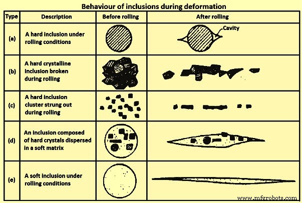
Gbr 1 Perilaku inklusi selama deformasi
Formasi 'Stringer', tipe (b) dan (c) pada Gambar 1, meningkatkan arah sifat mekanik, sehingga mempengaruhi ketangguhan dan daktilitas khususnya. Inklusi terburuk untuk ketangguhan dan keuletan, terutama dalam sifat arah ketebalan produk canai datar, adalah yang mengalami deformasi dengan matriks, seperti (d) pada Gambar 1. Untuk menghindari masalah ini, ukuran dan frekuensi inklusi yang merugikan harus dikendalikan dengan hati-hati. Terutama tidak ada inklusi pada baja tuang di atas ukuran kritis.
Karakterisasi inklusi adalah salah satu aspek terpenting untuk memastikan baja bersih. Inklusi adalah jenis cacat yang ada pada baja yang sangat mempengaruhi sifat-sifat seperti kemampuan poles, keuletan, dan kekuatan lelah baja. Oleh karena itu, inklusi diperlukan untuk dikontrol untuk produksi baja kinerja tinggi. Inklusi primer terbentuk selama perawatan baja di sendok. Sebagian besar dipindahkan ke terak sendok atau di lapisan. Namun, sisa inklusi masih harus dihilangkan melalui tahapan proses yang berurutan dan tambahan inklusi baru terbentuk selama pengecoran dan pemadatan.
Karena penurunan jumlah inklusi dengan bertambahnya ukuran, interval ukuran yang berbeda menimbulkan masalah yang berbeda. Sehubungan dengan kemampuan poles, sejumlah besar inklusi kecil lebih berbahaya daripada inklusi besar tetapi secara bersamaan lebih jarang hanya karena lebih sering terjadi. Di sisi lain, pada tingkat tegangan rendah, retak kritis, yang dapat menyebabkan kegagalan dalam masa pakai produk baja, kemungkinan besar tumbuh pada inklusi yang sangat besar. Inklusi ini jarang terjadi dan sulit untuk memperkirakan kepadatan kemunculannya dengan benar. Pada tingkat tegangan kelelahan menengah, inklusi ukuran sedang bersaing dengan cacat permukaan sebagai titik awal retak.
Inklusi dalam baja dapat terbentuk baik secara endogen (asli) atau eksogen. Inklusi endogen adalah hasil dari elemen paduan dalam baja yang bereaksi dengan gas terlarut (seperti oksigen) untuk membentuk inklusi padat dalam baja tuang. Inklusi dapat terbentuk selama deoksidasi, reoksidasi, atau pemadatan dari kelarutan spesies gas tereduksi dalam keadaan padat. Inklusi eksogen berasal dari sumber di luar baja cair, seperti slag entrainment, atau kerusakan refraktori.
Inklusi Endogen
Inklusi endogen adalah produk deoksidasi atau inklusi yang diendapkan selama pendinginan dan pemadatan baja.
Produk deoksidasi – Inklusi alumina dalam baja rendah karbon aluminium terbunuh (LCAK), dan inklusi silika (SiO2) dalam baja terbunuh silikon, yang dihasilkan oleh reaksi antara oksigen terlarut dan aluminium tambahan dan deoksidan silikon, adalah inklusi deoksidasi yang khas. Inklusi alumina bersifat dendritik ketika terbentuk di lingkungan oksigen tinggi. Inklusi alumina tipe klaster dari deoksidasi atau reoksidasi, adalah tipikal baja aluminium yang dibunuh. Inklusi alumina dengan mudah membentuk cluster tiga dimensi melalui tumbukan dan agregasi karena energi antarmuka yang tinggi. Inklusi individu dalam cluster dapat berdiameter 1 mikrometer hingga 5 mikrometer. Sebelum tumbukan, pecah atau agregasi dengan partikel lain, mereka dapat berbentuk pelat bunga, atau inklusi polihedral (agregat). Sebagai alternatif, inklusi alumina seperti karang diyakini sebagai hasil dari 'pematangan Ostwald' dari inklusi alumina dendritik atau berkerumun. Inklusi silika biasanya berbentuk bola karena berada dalam keadaan cair atau kaca dalam baja cair. Silika juga dapat menggumpal menjadi kelompok.
Inklusi yang diendapkan – Inklusi ini terbentuk selama pendinginan dan pemadatan baja. Selama pendinginan, konsentrasi oksigen terlarut/nitrogen/sulfur dalam cairan menjadi lebih tinggi sedangkan kelarutan unsur-unsur tersebut menurun. Dengan demikian inklusi seperti alumina, silika, aluminium nitrida (AlN), dan endapan sulfida. Sulfida terbentuk secara inter-dendrit selama pemadatan, dan sering ternukleasi pada oksida yang sudah ada dalam baja cair. Inklusi ini biasanya kecil (berukuran kurang dari 10 mikrometer).
Inklusi eksogen
Inklusi eksogen muncul terutama dari bahan kimia insidental (reoksidasi) dan interaksi mekanis baja cair dengan sekitarnya (terak entrainment dan erosi lapisan refraktori). Selama pemesinan, mereka menghasilkan obrolan, menyebabkan lubang dan lubang pada permukaan bagian mesin, seringnya kerusakan, serta keausan pahat yang berlebihan.
Inklusi eksogen selalu terkait dengan praktik dan ukuran serta komposisi kimianya sering mengarah pada identifikasi sumbernya, dan sumbernya terutama adalah reoksidasi, entrainment terak, erosi lapisan, dan reaksi kimia. Inklusi ini memiliki karakteristik sebagai berikut.
Ukuran besar – Inklusi eksogen dari erosi refraktori biasanya lebih besar daripada inklusi terak.
Komposisi senyawa / sifat multifase – Inklusi eksogen disebabkan oleh fenomena yaitu (i) akibat reaksi antara baja cair dan silika, FeO, dan MnO dalam terak dan lapisan refraktori dengan inklusi alumina yang dihasilkan dapat tetap berada di permukaannya, (ii) saat inklusi eksogen bergerak , karena ukurannya yang besar, mereka dapat menjebak inklusi deoksidasi seperti alumina pada permukaannya, (iii) inklusi eksogen bertindak sebagai situs inti heterogen untuk pengendapan inklusi baru selama gerakan mereka dalam baja cair, dan (iv) inklusi terak atau reoksidasi dapat bereaksi dengan lapisan refraktori atau mengeluarkan material lebih lanjut ke dalam baja cair.
Bentuk – Inklusi eksogen biasanya memiliki bentuk tidak beraturan, jika tidak bulat dari slag entrainment atau silika produk deoksidasi. Inklusi eksogen bola biasanya besar (lebih besar dari 50 mikrometer) dan sebagian besar multifase, tetapi inklusi deoksidasi bola biasanya kecil dan fase tunggal.
Kuantitas – Inklusi eksogen jumlahnya kecil dibandingkan dengan inklusi kecil.
Distribusi – Inklusi eksogen memiliki distribusi sporadis dalam baja dan tidak terdispersi dengan baik sebagai inklusi kecil. Karena mereka biasanya terperangkap dalam baja selama padat dan padat, kejadiannya tidak disengaja dan sporadis. Di sisi lain, mereka dengan mudah mengapung, jadi hanya berkonsentrasi di daerah bagian baja yang mengeras paling cepat atau di zona di mana pelepasan mereka dengan flotasi dalam beberapa cara terhambat. Oleh karena itu, inklusi ini sering ditemukan di dekat permukaan.
Efek pada sifat baja – Inklusi eksogen lebih merusak sifat baja daripada inklusi kecil karena ukurannya yang besar.
Satu masalah yang mengesampingkan sumber inklusi eksogen adalah mengapa inklusi besar seperti itu tidak mengapung dengan cepat begitu mereka ada di baja. Alasan yang mungkin adalah (i) pembentukan yang terlambat selama pembuatan baja, pemindahan, atau erosi dalam bejana metalurgi sehingga tidak cukup waktu untuk naik sebelum memasuki cetakan mesin pengecoran, (ii) kurangnya superheat yang cukup, (iii) aliran fluida selama pemadatan menginduksi jebakan terak cetakan, atau (iv) penarikan kembali inklusi terapung sebelum mereka sepenuhnya memasuki terak.
Inklusi eksogen dari reoksidasi – Bentuk inklusi makro besar yang paling umum dari reoksidasi ditemukan dalam baja adalah kluster alumina. Udara adalah sumber reoksidasi yang paling umum, yang dapat terjadi (i) baja cair di tundish bercampur dengan udara dari permukaan atasnya pada awal penuangan karena turbulensi yang kuat dan lapisan oksida pada permukaan cairan yang mengalir terlipat ke dalam cairan, membentuk bidang partikel oksida yang lemah, (ii) udara tersedot ke dalam baja cair pada sambungan antara sendok dan tundish, dan antara tundish dan cetakan, dan (iii) udara menembus ke dalam baja dari permukaan atas baja dalam sendok, tundish, dan cetakan selama penuangan.
Selama jenis reoksidasi ini, elemen deoksidasi, seperti aluminium, kalsium, dan silikon dll. dioksidasi secara istimewa dan produknya berkembang menjadi inklusi, biasanya satu hingga dua besaran lebih besar daripada inklusi deoksidasi. Solusi untuk mencegah reoksidasi semacam ini adalah dengan membatasi paparan udara pada proses pengecoran. Hal ini dapat dilakukan (i) dengan menyelubungi tirai gas inert menggunakan manifold cincin baja atau cincin tahan api berpori di sekitar sambungan antara ladle dan tundish, dan antara tundish dan cetakan, (ii) dengan mengeluarkan beberapa gas argon ke dalam tundish sebelum menuangkan, dan ke dalam permukaan tundish selama menuangkan, dan (iii) dengan mengontrol injeksi gas argon di sendok untuk menghindari pembentukan mata.
Sumber reoksidasi lainnya adalah terak dan refraktori pelapis. Dengan mekanisme reoksidasi ini, inklusi di dalam baja tumbuh saat dekat dengan terak atau lapisan antarmuka melalui reaksi SiO2 / FeO / MnO + [Al] =[Si] / [Fe] / [Mn] + Al2O3. Hal ini menyebabkan inklusi alumina yang lebih besar dengan komposisi variabel. Fenomena ini selanjutnya mempengaruhi inklusi eksogen dengan cara yang berbeda yaitu (i) reaksi ini dapat mengikis dan meratakan permukaan lapisan, yang mengubah pola aliran fluida di dekat dinding lapisan dan dapat menyebabkan percepatan pemecahan lapisan lebih lanjut, dan (ii) a inklusi eksogen besar dari lapisan rusak atau terak yang terperangkap dapat menjebak inklusi kecil, seperti produk deoksidasi, dan juga bertindak sebagai inti heterogen untuk presipitat baru yang memperumit komposisi inklusi eksogen.
Untuk mencegah reoksidasi dari terak dan lapisan tahan api, sangat penting untuk menjaga kandungan SiO2, FeO, dan MnO yang rendah. Telah dilaporkan bahwa batu bata alumina atau zirkonia tinggi yang mengandung silika bebas tingkat rendah lebih sesuai untuk digunakan.
Inklusi eksogen dari slag entrainment – Setiap operasi pembuatan baja atau pemindahan baja cair melibatkan pencampuran turbulen antara terak dan logam, terutama selama pemindahan antar bejana. Ini menghasilkan partikel terak yang tersuspensi dalam baja. Inklusi terak, berukuran 10 mikrometer hingga 300 mikrometer, mengandung sejumlah besar CaO(kapur) atau MgO (magnesia), dan biasanya cair pada suhu baja cair dan karenanya berbentuk bulat. Penggunaan tundish berbentuk 'H' dan menuangkannya melalui dua sendok akan mengurangi penumpukan terak selama periode penggantian sendok. Penyebab yang mempengaruhi masuknya slag ke dalam baja cair selama proses pengecoran kontinyu antara lain (i) selama operasi pemindahan dari ladle ke tundish dan dari tundish ke cetakan terutama untuk penuangan terbuka, vortexing pada permukaan atas baja cair yang pada level rendah baja cair dapat dihindari dengan beberapa cara seperti mematikan penuangan sebelum permulaan vortexing, (ii) emulsifikasi dan slag entrainment di permukaan atas terutama di bawah pengadukan gas di atas laju aliran gas kritis, (iii) turbulensi di meniskus dalam cetakan, dan (iv) sifat terak seperti tegangan antarmuka dan viskositas terak.
Sebagai contoh, bubuk cetakan dapat terperangkap ke dalam baja cair karena (i) turbulensi pada meniskus (Gambar 2A), (ii) vortexing (Gambar 2C), (iii) emulsifikasi yang disebabkan oleh gelembung yang bergerak dari baja ke terak [Gbr 2B dan 2D), (iv) menyedot sepanjang dinding nozzle karena perbedaan tekanan (2E), (v) aliran kecepatan tinggi yang memotong terak dari permukaan (2A), dan (vi) fluktuasi level (Gbr 2B) .
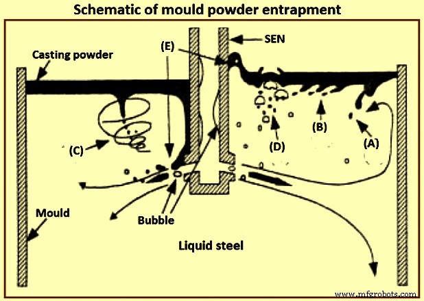
Gbr 2 Skema jebakan bubuk cetakan
Tegangan antarmuka antara baja dan bubuk tuang cair menentukan ketinggian meniskus baja, dan kemudahan masuknya fluks. Khususnya tegangan antarmuka 1,4 newton per meter (N/m) untuk terak kapur-silika-alumina yang kontak dengan besi murni menghasilkan ketinggian meniskus sekitar 8 mm. Tegangan antarmuka dikurangi hingga nilai yang rendah oleh spesies aktif permukaan seperti belerang atau dengan reaksi pertukaran antarmuka seperti oksidasi aluminium dalam baja oleh oksida besi dalam terak. Tegangan antarmuka yang sangat rendah terkait dengan reaksi kimia dapat memberikan turbulensi spontan pada antarmuka, melalui efek Marangoni. Turbulensi seperti itu dapat membuat emulsi pada antarmuka, menciptakan butiran terak yang tidak diinginkan dalam baja.
Inklusi eksogen dari erosi / korosi lapisan tahan api – Erosi refraktori, yang meliputi pasir blok sumur, kotoran lepas, bata tahan api yang pecah, dan partikel lapisan keramik, adalah sumber yang sangat umum dari inklusi eksogen besar yang biasanya padat dan terkait dengan bahan sendok dan tundish itu sendiri. Ini biasanya material berukuran besar dan tidak beraturan. Inklusi eksogen dapat bertindak sebagai situs untuk nukleasi heterogen alumina, atau agregat dengan inklusi pribumi lainnya. Terjadinya produk erosi tahan api atau inklusi yang diperkenalkan secara mekanis dapat sepenuhnya merusak kualitas baja yang sangat bersih.
Dalam beberapa penelitian untuk menyelidiki proses erosi, telah dilaporkan bahwa 'kaca refraktori' dan 'lapisan reaksi pada permukaan batu bata' dibentuk dengan baja cair pada suhu 1.550 derajat C hingga 1.600 derajat C. Penyumbatan inklusi besar pada permukaan lapisan juga dapat dilepaskan ke dalam baja cair.
Erosi lapisan biasanya terjadi di daerah aliran turbulen, terutama bila dikombinasikan dengan reoksidasi, suhu tuang yang tinggi, dan reaksi kimia. Parameter yang sangat mempengaruhi erosi lapisan dijelaskan di bawah ini.
Beberapa grade baja cukup korosif (seperti mangan tinggi dan grade yang hampir tidak terbunuh dan memiliki kandungan oksigen terlarut yang tinggi) dan menyerang lapisan batu bata.
Reaksi reoksidasi, seperti aluminium terlarut dalam baja cair mengurangi silika dalam refraktori lapisan, menghasilkan inklusi berbasis oksida besi yang sangat reaktif dan membasahi bahan pelapis, menyebabkan erosi refraktori lapisan di area turbulensi fluida tinggi.
Komposisi dan kualitas bata memiliki pengaruh yang cukup besar terhadap kualitas baja. Di salah satu pabrik, tiga jenis bahan (alumina tinggi, Al2O3-SiC-C, dan MgO-C dengan laju keausan 1 mm / panas, 0,34 mm / panas, 0,16 mm / panas masing-masing) telah diadopsi di pabrik. slag line, dimana refraktori cenderung rusak oleh erosif tundish flux dan slag, dan bata MgO-C menunjukkan durabilitas tertinggi di antara ketiganya. Mangan oksida lebih disukai menyerang bagian yang mengandung silika dari refraktori. Butir alumina dan zirkonia dengan kemurnian sangat tinggi dapat menahan serangan oksida mangan.
Erosi refraktori yang cepat dari baja mangan tinggi dapat dibatasi dengan (i) penggunaan refraktori alumina atau zirkonia dengan kemurnian sangat tinggi, (ii) meminimalkan oksigen dengan sepenuhnya membunuh baja dengan deoksidan kuat seperti aluminium atau kalsium, dan mencegah penyerapan udara. Lapisan tundish berbasis silika lebih buruk daripada lapisan semprot berbahan dasar magnesium. Refraktori alumina tinggi disarankan sebagai yang paling menjanjikan. Memasukkan kalsium oksida ke dalam refraktori nosel dapat membantu dengan mencairkan inklusi alumina di dinding, selama difusi CaO ke antarmuka cukup cepat dan erosi nosel tidak menjadi masalah. Erosi nozzle dapat diatasi dengan mengontrol komposisi refraktori nozzle, (misalnya menghindari pengotor natrium, kalium, dan silikon), atau melapisi dinding nozzle dengan alumina murni, boron nitrida, atau bahan tahan lainnya. Tahan api pada permukaan dinding selubung harus dipilih untuk meminimalkan reaksi dengan baja yang menciptakan inklusi dan penyumbatan.
Kecepatan yang berlebihan dari baja cair mempengaruhi erosi lapisan di sepanjang dinding di tundish, seperti zona saluran masuk. Sebuah pad dapat digunakan untuk mencegah bagian bawah tundish dari erosi, serta mengontrol pola aliran. Telah disarankan bahwa kecepatan baja cair lebih dari 1 meter per detik berbahaya sehubungan dengan erosi.
Kontak yang berlebihan atau waktu pengisian dan suhu tinggi memperburuk masalah erosi. Selama periode penahanan yang lama di sendok, inklusi yang lebih besar dapat mengapung ke dalam terak sendok. Namun semakin lama baja bersentuhan dengan lapisan sendok, semakin besar kecenderungan produk erosi sendok. Solusi didasarkan pada pengembangan refraktori yang sangat stabil untuk grade baja tertentu, pengembangan insert refraktori tahan aus yang padat untuk area aliran tinggi, dan mencegah reoksidasi.
Inklusi eksogen dari reaksi kimia – Reaksi kimia menghasilkan oksida dari modifikasi inklusi ketika perawatan kalsium tidak dilakukan dengan benar. Mengidentifikasi sumber inklusi ini tidak selalu mudah, sebagai contoh, inklusi yang mengandung kalsium oksida juga dapat berasal dari terak yang terperangkap.
Aglomerasi inklusi dan penyumbatan – Aglomerasi inklusi padat dapat terjadi pada permukaan apa pun yang dibantu oleh efek tegangan permukaan, termasuk pada permukaan refraktori dan gelembung. Sudut kontak alumina yang tinggi dalam baja cair (134 derajat hingga 146 derajat) mendorong inklusi untuk menempel pada refraktori untuk meminimalkan kontak dengan baja. Temperatur tinggi 1,530 derajat C memungkinkan sintering alumina terjadi. Sudut kontak yang besar dan ukuran inklusi yang lebih besar mendukung aglomerasi inklusi. Karena tumbukan dan aglomerasi, inklusi dalam baja cenderung tumbuh dengan bertambahnya waktu dan suhu. Pertumbuhan inklusi melalui tumbukan, aglomerasi, dan koagulasi dalam ingot telah menjadi subjek berbagai penelitian, di mana simulasi numerik nukleasi inklusi mulai dari penambahan deoksidan dan pertumbuhan dengan tumbukan dan difusi dari ukuran nano ke ukuran mikro dilaporkan.
Dasar-dasar sintering alumina ke dalam kluster membutuhkan penyelidikan lebih lanjut, meskipun beberapa penelitian telah menggunakan teori fraktal untuk menggambarkan morfologi kluster (fitur). Contoh paling jelas dari aglomerasi inklusi pada permukaan refraktori lapisan adalah penyumbatan nosel selama pengecoran baja cair secara terus menerus.
Pengaruh aliran fluida dan solidifikasi pada inklusi – Distribusi inklusi dalam pengecoran baja kontinu dipengaruhi oleh aliran fluida, perpindahan panas, dan pemadatan baja cair. Indeks populer untuk penjeratan inklusi adalah kecepatan maju kritis dari front solidifikasi, yang dipengaruhi oleh beberapa parameter seperti bentuk inklusi, densitas, energi permukaan, konduktivitas termal, laju pendinginan (laju solidifikasi), dan kondisi penonjolan dari front solidifikasi. Telah dilaporkan bahwa jebakan dikendalikan oleh gaya tarik dan gaya antarmuka (gaya Van der Waals). Telah disarankan bahwa semakin cepat laju pemadatan, semakin tinggi kemungkinan jebakan. Probabilitas jebakan berkurang dengan meningkatnya waktu pemadatan, lebih sedikit segregasi, tonjolan yang lebih kecil di bagian depan pemadatan. Jarak lengan dendrit memiliki efek besar pada jebakan inklusi dan terkait dengan fenomena mendorong, menelan; atau jebakan.
Operasi pengecoran berkelanjutan, inklusi, dan baja bersih
Operasi pengecoran kontinu mengontrol kebersihan baja. Sebuah studi sistematis penghapusan inklusi telah menemukan bahwa pengobatan sendok menurunkan inklusi sekitar 65% sampai 75%, tundish menghilangkan inklusi sekitar 20% sampai 25%, meskipun reoksidasi kadang-kadang telah terjadi, dan cetakan menghilangkan inklusi sekitar 5%. sampai 10%. Pengoperasian tundish memiliki pengaruh besar pada kebersihan baja. Faktor penting dalam pengoperasian tundish yang berpengaruh pada kebersihan baja adalah kedalaman dan kapasitas tundish, transisi casting, refraktori lapisan tundish, fluks tundish, pengadukan gas argon, dan kontrol aliran tundish.
Terak teratas – Terak atas di ladle dan tundish menyediakan beberapa fungsi seperti (i) isolasi baja cair baik secara termal (untuk mencegah kehilangan panas yang berlebihan) dan secara kimia (untuk mencegah masuknya udara dan reoksidasi), dan (ii) penyerapan inklusi untuk memberikan pemurnian baja tambahan. Fluks tundish yang umum adalah sekam padi yang dibakar, yang murah, isolator yang baik, dan memberikan cakupan yang baik tanpa pengerasan kulit. Namun, sekam padi mengandung silika yang tinggi (sekitar 80% SiO2), yang dapat direduksi untuk membentuk sumber inklusi. Mereka juga sangat berdebu dan dengan kandungan karbon yang tinggi, (sekitar 10% C), dapat menyebabkan kontaminasi baja karbon ultra rendah.
Fluks dasar (berbasis CaO-Al2O3-SiO2, dan silika kurang dari 10%) secara teoritis jauh lebih baik daripada sekam padi selama pemurnian baja LCAK, dan telah berkorelasi dengan oksigen yang lebih rendah di tundish. Misalnya, dalam sebuah penelitian, oksigen total mengalami penurunan dari kisaran 25 ppm (parts per million) dan 50 ppm ke kisaran 19 ppm dan 35 ppm dengan kebasaan fluks yang meningkat dari 0,83 menjadi 11. Dalam salah satu pabrik baja, penggunaan fluks dasar, oksigen total dalam cetakan telah dilaporkan lebih rendah, dan cacat produk baja telah menurun. Namun, kemungkinan besar, fluks dasar tidak efektif karena mudah membentuk kerak di permukaan, karena laju lelehnya yang lebih cepat dan suhu kristalisasi yang tinggi. Kerak ini menghasilkan evolusi mata bebas terak terbuka di sekitar selubung ladle selama padat, yang tidak hanya menyediakan area yang berlebihan untuk reoksidasi, tetapi juga memungkinkan kehilangan panas radiasi yang signifikan dan ketidaknyamanan bagi operator di platform kerja. Juga, fluks dasar biasanya memiliki viskositas yang lebih rendah. Oleh karena itu, mereka lebih mudah tertarik. Untuk menghindari masalah ini, satu pabrik baja telah menggunakan fluks dua lapisan, dengan fluks dasar titik leleh rendah di bagian bawah untuk menyerap inklusi, dan lapisan atas fluks berbasis sekam padi untuk memberikan insulasi. Ini telah menurunkan total oksigen dari 22,5 ppm menjadi 16,5 ppm.
Perangkat kontrol kedalaman, kapasitas, dan aliran tundish – Pola aliran tundish harus dirancang untuk meningkatkan waktu tinggal baja cair, mencegah 'korsleting' dan mendorong penghapusan inklusi. Aliran tundish dikendalikan oleh geometri, level, desain saluran masuk (selubung), dan perangkat kontrol aliran seperti bantalan benturan, bendung, bendungan, baffle, dan filter. Tundish dalam dengan kapasitas besar meningkatkan waktu tinggal baja cair dan partikel dan karenanya mendorong penghilangan inklusi. Tundish yang dalam juga menghambat pembentukan vortex, memungkinkan lebih banyak waktu untuk transisi ladle sebelum slag entrainment menjadi masalah. Ukuran tundish untuk baja LCAK telah meningkat secara bertahap di seluruh dunia selama 20 tahun terakhir, biasanya mencapai 60 ton hingga 80 ton dengan kedalaman sekitar 1,8 meter inci untuk mesin pengecoran kontinu pelat.
Jika disejajarkan dengan benar, dan mungkin bersama dengan bendung dan bendungan, bantalan tuang dapat meningkatkan kebersihan baja, terutama selama pertukaran sendok. Sebagai contoh, penambahan bantalan tuang di salah satu pabrik baja telah menurunkan alumina selama transisi sendok dari 48 ppm menjadi 15 ppm. Di pabrik baja lain, oksigen total telah menurun dari 26 ppm (dengan bantalan kubah) menjadi 22 ppm (dengan bantalan dop). Di pabrik baja lainnya, kebersihan baja telah ditingkatkan dengan menempatkan 77 lubang di bendungan mereka, menjadikannya sebagai filter parsial. Di satu pabrik baja lainnya, teknik serupa yang terdiri dari baffle yang dikombinasikan dengan penutup tundish awal telah menurunkan rata-rata oksigen total dalam tundish selama pengecoran kondisi tunak dari 39 +/- 8 ppm menjadi 24 +/- 5 ppm.
Filter keramik dan filter CaO sangat efektif dalam menghilangkan inklusi. Namun, biaya dan waktu pengoperasian yang efektif sebelum penyumbatan biasanya membuat penggunaannya menjadi mahal. Menyuntikkan gas inert ke dalam tundish dari dasarnya meningkatkan pencampuran baja cair, dan mendorong tumbukan dan penghilangan inklusi. Di salah satu pabrik baja, dengan menerapkan teknologi ini total oksigen telah berhasil diturunkan menjadi 16 ppm di tundish. Namun, bahaya dari teknologi ini adalah bahwa setiap gelembung yang mengandung inklusi yang lolos dari tundish dan terperangkap dalam untaian menyebabkan cacat yang parah. Telah dilaporkan bahwa fraksi luas oksida (0,001 %) baja dalam tundish berkurang 25% dengan teknik ini dibandingkan dengan yang tanpa teknik ini.
Transisi transmisi – Transisi pengecoran terjadi pada awal urutan pengecoran, selama pertukaran sendok dan perubahan nozzle, dan pada akhir pengecoran. Transisi ini bertanggung jawab atas sebagian besar cacat kebersihan. Inklusi sering dihasilkan selama transisi dan dapat bertahan untuk waktu yang lama, sehingga mencemari banyak baja. Indeks cacat sliver pada awal pemanasan pertama telah ditemukan 5 kali lebih tinggi dari pada pertengahan pemanasan pertama dan lebih dari 15 kali lipat dari pemanasan berturut-turut. Selama periode pengecoran yang tidak stabil ini, entrainment terak dan penyerapan udara lebih mungkin terjadi, yang menyebabkan masalah reoksidasi. Sendok 'membuka sendiri' terbuka sendiri tanpa harus menusuk nosel. Lancing membutuhkan pelepasan selubung dan ini memungkinkan reoksidasi terjadi, terutama selama 650 mm hingga 1.200 mm pertama dari pengecoran. Pemanas terbuka dengan lanced memiliki kadar oksigen total sekitar 10 ppm lebih tinggi dari pemanasan terbuka sendiri. Pengepakan pasir pembuka sendok yang hati-hati membantu dalam mencapai pembukaan sendiri sendok. Pasir sendok juga merupakan sumber reoksidasi karena kandungan silika yang tinggi.
Salah satu perbaikan selama transisi sendok adalah menghentikan aliran cairan ke dalam cetakan sampai tundish terisi dan menggelembungkan gas melalui sumbat untuk mendorong flotasi inklusi. Perbaikan lainnya adalah membuka sendok baru dengan selubung terendam. Dengan ukuran ini, oksigen total telah menurun di salah satu pabrik baja dari 41 +/- 14 ppm menjadi 31 +/- 16 ppm dengan kualitas yang lebih konsisten di seluruh rangkaian.
As an example, at one of the steel plant, total oxygen in tundish during transitions is 50 ppm to 70 ppm, compared with only 25 ppm to 50 ppm at steady state. At other steel plants, the difference is only 3 ppm. One of the steel plants has reported transitions to have total oxygen only 19.2 ppm relative to 16 ppm at steady state while another steel plant has reported total oxygen of 27 +/- 5 ppm during transitions and 24 +/- 5 ppm during steady casting. At one other steel plant, the nitrogen pickup in tundish is 5 ppm to 12 ppm during the start period of the teeming which decreases to 0 ppm to 2 ppm after around 12 minute of teeming (steady casting state).
Near the end of the teeming of a ladle, ladle slag can enter the tundish, due to the vortex formed in the liquid steel near the ladle exit. This phenomenon needs some steel to be kept in the ladle upon closing (e.g. a four ton of ‘heel’). In addition, the tundish depth drops after ladle close, which disrupts normal tundish flow and can produce slag vortexing, slag entrainment, and increased total oxygen in the mould.
Shrouding, argon protection, and sealing – Steel shrouding from ladle to the mould includes ladle slide gate shrouding, ladle collector nozzle, ladle shroud connection, tundish well block, and top plate of the tundish slide gate. Shroud design variations are of great importance in the operations of the tundish-to-mould transfer of liquid steel. Use of an optimized shrouding system greatly lowers reoxidation during transfer operations. For example, use of a ladle shroud has lowered nitrogen pickup from 24 ppm to 3 ppm relative to open pouring at one of the steel plant. In another steel plant, replacing the tundish pour box with a ladle shroud and dams has lowered nitrogen pickup (ladle to tundish) from 7.5 ppm to 4 ppm, and also has lowered slag entrainment during transitions. At one other steel plant, improving the shroud system from ladle to tundish has lowered the nitrogen pickup from 14 ppm to 3 ppm.
Shrouding the ladle to tundish stream at one of the steel plants has lowered the dissolved aluminum loss from 130 ppm to 70 ppm and has lowered the total oxygen increase by 12 ppm. When pouring without shrouds, which is common in billet casting, the turbulence of the casting stream is very important. A smooth stream entrains much less oxygen than a turbulent or ‘ropy’ stream. For the production of a smooth stream between the tundish and the mould in these operations, the metering nozzle edges are to be maintained and high speed flow in the tundish across the nozzles is to be avoided. A protective tundish cover with carefully sealed edges also helps in lowering total oxygen from 41.5 ppm to 38 ppm.
A variety of inert gas shrouding systems is now available. Total oxygen in the cast product (LCAK steel) can be lowered from 48.5 ppm to 28.5 ppm by shrouding between the ladle and the tundish, and to 23 ppm by this shrouding plus argon sealing. It is very important to carefully seal the joints in the shrouds, both to improve cleanliness and to prevent clogging. Improving the bayonet system between the ladle nozzle and ladle shroud, lowers the nitrogen pickup there from 8 ppm to less than 1 ppm. Stiffening the submerged entry nozzle (SEN) holder and increasing its maintenance has lowered the initial nitrogen pickup from 1.8 ppm to 0.3 ppm in one of the steel plants.
Inert gas can protect the steel from air reoxidation in several ways. To combat air entrainment at the beginning of a cast, the tundish can be purged with inert gas (to displace the air) prior to ladle opening, which lowers both the total oxygen and the nitrogen pickup during startup. Argon injection to pressurize the shrouds can help to prevent the liquid steel from air reoxidation through any joints or leaks. Guidelines for minimum argon gas flow to ensure positive pressure inside the nozzle are to be made. In addition, flooding the joints with argon gas ensures that any leaks aspirate inert gas and not air.
Injecting argon into the tundish stopper rod and improved sealing at one steel plant has decreased nitrogen pickup from tundish to cast product from 5 ppm to 1.8 ppm, has lowered total oxygen in the cast product from 31 ppm to 22 ppm, has decreased the size of alumina clusters in the cast product, and has decreased clogging. Elsewhere, argon injection through the stopper rod lowered the number of inclusions detected by the Mannesmann inclusion detection by analysis surfboards (MIDAS) method by 25 % to 80 %. Injection of argon gas purge through upper plate of the sliding gate has lowered the quantity of 50 micrometers to 100 micrometers sized inclusions from 3 per square centimeter to 0.6 per square centimeter, and lowered 100 micrometers to 200 micrometers macro-inclusions from 1.4 per square centimeter to 0.4 per square centimeter.
Clogging and new techniques at SEN – The nozzle is one of the few control parameters which is relatively inexpensive to change, yet has a profound influence on the flow pattern and hence on the quality of the cast product. Nozzle parameters include bore size, port angle and opening size, nozzle wall thickness, port shape (round, square, or oval), number of ports (bifurcated or multiport), nozzle bottom design (well, flat , or sloped), and submergence depth. Both too large and too small submergence depth increases problems with longitudinal cracks and transverse depressions.
One of the studies has found the occurrence of corundum (Al2O3) covering the bore surface of nozzles used to pour aluminum killed steel ingot early in 1949. Another study has found that nozzle blockage occurred with high levels aluminum (0.0036 %) and that nozzle sectioning revealed dendritic growth of alumina from the nozzle wall onto the bore. Yet another study has observed clogs of aluminum, zircon, titanium, and the rare earths.
Nozzle clogs are caused by reoxidation, or by the accumulation of solid oxides or sulphides, such as alumina and calcium sulphide (CaS) in the steel. In addition to interfering with the production process, tundish nozzle / SEN clogging is detrimental to steel cleanliness for several reasons such as (i) dislodged clogs either become trapped in the steel, or they change the flux composition, leading to defects in either case, (ii) clogs change the nozzle flow pattern and jet characteristics leaving the nozzle, which disrupt flow in the mould, leading to slag entrainment and surface defects, and (iii) clogging interferes with mould level control, as the flow control device (stopper rod or slide gate) tries to compensate for the clog.
The cure for the nozzle clog problem includes improving steel cleanliness by improving ladle practices, implementing smooth and non-reacting refractories, and controlling fluid flow though the nozzle for ensuring a smooth flow pattern. Changing from a three-plate slide gate system to a stopper rod system has reduced clogging at one of the steel plant. Several practices can be used to minimize clogging. In addition to taking general measures to minimize inclusions, clogging through refractory erosion can be countered by controlling nozzle refractory composition, (e.g. avoiding sodium, potassium, and silicon impurities), or coating the nozzle walls with pure alumina, boron nitride, or other resistant material. There are several new techniques at SEN which have reported to improve the fluid flow pattern and inclusion removal, such as (i) swirl-nozzle technique, (ii) step nozzle technique, (iii) multi-ports nozzle, and (iv) oval offset bore throttle plate.
Swirl-nozzle technique – A fixed blade placed at the upstream end of the SEN induces a swirl flow in nozzle. Centrifugal force generated by the swirling flow in the nozzle can distribute the liquid steel equally to its two spouts. Since liquid steel stream with centrifugal force has the maximum velocity in the vicinity of the wall inside the nozzle, it tends to flow out of the upper part of the spout. Hence, the velocity distribution which tends to have higher values toward the lower part of the spout with a conventional nozzle can become uniform. It has been reported that by using this swirl nozzle for the continuous casting, the defect ratio of finish products (coils) has decreases to 25 % of the conventional nozzles, and casting speed has riseby 30 %. Its cost is higher only by 20 % than the cost of the conventional and hence it is cheaper than using an ‘electro-magnetic brake’. This swirl flow pattern can also be generated by the ‘electro-magnetic stirring’ at the nozzle, which can also improve the solidification structure of the cast steel as well.
Step nozzle – The flow pattern at out-ports of conventional SEN is uneven or biased because of the sliding gate of SEN. This biased flow pattern (swirl flow at out-ports of SEN) increases the impingement of the jet, and hence worsens inclusion removal to top surface. By using inner annular steps, the biased flow in mould can be weakened. The calculation suggests that the removal fraction of 50 micrometers inclusions to the top surface of the mould is 2 % with the conventional SEN, but increases to 7 % with the use of the stepped SEN.
Oval offset bore throttle plate – In the conventional system, gate throttling results in a highly skewed and biased flow in the tundish-to-mould flow channel both upstream and downstream of the gate. These effects have considerably diminished the offset bore system. The offset gate design extracts the fluid more centrally from the tundish well nozzle. Hence, the system is less sensitive to any build-up on the walls of the well nozzle, which extends the useful life of the tundish well nozzle and hence, allowing longer tundish sequences. In practice, it has also been found that clogging within the plates of the offset bore gate is considerably reduced as compared to the conventional gate.
Multiple out-ports – It is well known that the surface velocity of the mould has a big effect on slag entrainment and top surface fluctuation. Several defects are related to the surface velocity of the mould. Thus decreasing the surface velocity is very important to improve the steel cleanliness. This task can be targeted by using multiple out-ports at SEN. Addition of a bottom hole at SEN lowers the momentum of the side jets so it is possible to get a good steel flow and meniscus condition even under high throughput which is better stabilized.
Mould and operation of continuous casting machine
The continuous casting mould region is the last refining step where inclusions either are safely removed into the top slag layer or they become entrapped into the solidifying shell to form permanent defects in the steel product. Mcpherson has used the words ‘mould metallurgy’ in 1985 to emphasize the importance of the mould to improve steel cleanliness. The mould flow pattern is very important for avoiding defects since it affects particle transport and removal to the top slag or entrapment by the solidifying shell.
Top surface control – Directing too much flow towards the top surface generates surface defects, due to transients, turbulence at the meniscus, and inclusion problems from slag entrainment. However, decreasing surface flows too much can also generate problems. These include surface defects due to the meniscus region becoming too stagnant, and a higher fraction of incoming inclusion particles being sent deep before they can be removed into the slag. Hence, a balance is to be found in order to optimize the flow parameters to avoid defects.
The most obvious source of surface defects is the capture of foreign particles into the solidifying shell at the meniscus. If the steel jet is directed too deep or has too little superheat, then the liquid surface has very little motion and becomes too cold. This can lead to freezing of the steel meniscus, which aggravates the formation of meniscus hooks. This allows inclusions and bubbles to be captured, the latter forming pinholes just beneath the surface of the cast product. As an example, decreasing surface velocity below 0.4 metre/second (m/s) has been measured to increase surface pinhole defects. For avoiding these problems, the flow pattern is to be designed to exceed a critical minimum velocity across the top surface, which is estimated to be around 0.1 m/s to 0.2 m/s.
Slag entrainment is less likely with deeper nozzle submergence and slower casting speed. For avoiding shearing slag in this manner, the surface velocity is to be kept below a critical value. This critical velocity has been measured in water – oil models as a function of viscosity and other parameters. Entrainment is more difficult for shallower slag layers, higher slag viscosity, and higher slag surface tension.
A maximum limit of the argon gas injection flow rate into the nozzle has been reported as a function of the casting speed, beyond which mould slag entrainment takes place. Increasing casting speed tends to increase transient turbulent fluctuations, and worsens the extent of flow pattern asymmetries. This in turn worsens detrimental surface turbulence and level fluctuations. Improving internal cleanliness frequently needs limiting the maximum casting speed, to avoid pencil pipe defects. Lower casting speed and avoiding variations in casting speed both reduce the rate of slivers. More precisely, it is important to lower the liquid mass flow rate in order to control the jet velocity leaving the nozzle.
Fluid flow pattern – The mould flow pattern is controlled by adjustable parameters such as nozzle geometry nozzle submergence depth, argon gas injection rate, and the application of electro-magnetic forces. It also depends on parameters which normally cannot be adjusted to accommodate the flow pattern, such as the position of the flow control device (slide gate or stopper rod), nozzle clogging, casting speed, strand width, and strand thickness. All of these parameters together form a system which is to be designed to produce an optimal flow pattern for a given operation.
Bubbles, which are injected into the nozzle and the mould, have five effects related to the control of tge steel quality. These effects are (i) helping to reduce nozzle clogging, (ii) helping influence and control the flow pattern in the mould, (iii) generating serious top surface fluctuation even emulsification if gas flow rate is too large, (iv) capturing inclusions as they flow in the liquid steel, and (v) bubbles entrapped solid oxide particles captured by solidified shell eventually lead to surface slivers or internal defects.
Normally, low gas flow tends to double-roll flow pattern, while a high argon flow rate induces single-roll flow. This phenomenon has been studied as early as in 1983. For maintaining a stable double roll flow pattern, which is frequently optimal, the argon is to be kept safely below a critical level. Excessive argon injection can generate transient variation of the jets entering the mould, introduce asymmetry in the mould cavity, and increase surface turbulence. Argon gas bubbles can also be trapped in the solidifying steel shell to form blister defects, such as pencil pipe in the finish product.
It has been observed that inclusion entrapment varies from side to side, which suggests a link with the variations in the transient flow structure of the lower recirculation zone, and the asymmetrical flow pattern (Fig 3), which can be induced by nozzle clogging, by turbulence, and by excessive argon gas injection. It is especially important to keep nearly constant the liquid steel level in the mould, powder feeding rate, casting speed, gas injection rate, slide gate opening, and nozzle position (alignment and submergence).
Electro-magnetic forces can be applied to the liquid steel in a number of ways to alter considerably the flow pattern in the strand. It has been reported that electro-magnetic stirring of outer strands can improve the steel cleanliness, lowering total oxygen in the cast product from 30 ppm to 20 ppm. Another example is the electro-magnetic brake (EMBR), which bends the jet and shortens its impingement depth, to lessen the likelihood of capture by the solidified shell deep in the strand.
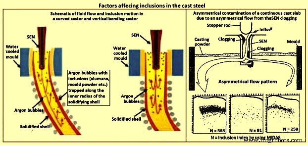
Fig 3 Factors affecting inclusions in cast steel
Casting machine curvature – Continuous casting machines with curved mould are known to entrap more particles than straight (vertical) mould casting machines (Fig 3), since the particles gradually move upwards towards the inside radius while they spiral with the liquid in the lower recirculation zone. Majority of the particles are captured 1 m to 3 m below the meniscus, independent of casting speed, which corresponds to a specific distance through the strand thickness. Frequently, inclusions concentrate at surface and one-eighth to one-fourth of the thickness from the top of the inside radius surface. The vertical bending casting machine has fewer inclusions and pinholes, which are distributed deeper, relative to the curved casting machine. Particle entrapment defects such as pencil pipe can be lessened if at least the top 2.5 m section of the casting machine is straight (vertical).
Inclusions detection methods
The quantity, size distribution, shape and composition of inclusions are required to be measured at all stages of the production of steel. Measurement techniques range from direct methods, which are accurate but costly, to indirect methods, which are fast and inexpensive, but are only reliable as relative indicators. The inclusion detection methods are sometimes divided into two categories namely (i) off-line methods, and (ii) online methods.
Direct methods
There are several direct methods to evaluate steel cleanliness. These methods are described below.
Inclusion evaluation of solid steel sections
Several traditional methods directly evaluate inclusions in a two dimensional section through solidified product samples. The last five of the methods described below add the ability to measure the composition of the inclusions.
Metallographic microscope observation (MMO) – MMO method can only reveal the two-dimensional section of an inclusion though the inclusions are three-dimensional in nature.
Image analysis (IA) – This enhancement to MMO improves on eye evaluation by using high speed computer evaluation of video-scanned microscope images to distinguish dark and light regions based on a grey scale cutoff.
Sulphur print – It is a popular and inexpensive macro-graphic method which distinguishes macro-inclusions and cracks by etching sulphur rich areas. It has the same issues as the other two-dimensional methods.
Scanning electron microscopy (SEM) – This method clearly reveals the three-dimensional morphology and the composition of each inclusion. Composition can also be measured with ‘electron probe micro analyzer’ (EPMA).However, extensive sample preparation is needed to find and expose the inclusion(s).
Optical emission spectrometry with pulse discrimination analysis (OES-PDA) – The optical emission spectrometry (OES) method analyzes elements dissolved in liquid steel. Inclusions cause high intensity spark peaks (relative to the background signal from the dissolved elements), which are counted to give the PDA (pulse discrimination analysis) index.
Laser micro-probe mass spectrometry (LAMMS) – In this method, individual particles are irradiated by a pulsed laser beam, and the lowest laser intensity above a threshold value of ionization is selected for its characteristic spectrum patterns due to their chemical states. Peaks in LAMMS spectra are associated with elements, based on comparison with reference sample results.
X-ray photoelectron spectroscopy (XPS) – This method use x-rays to map the chemical state of individual inclusions which greater than 10 micrometers in size.
Auger electron spectroscopy (AES) – This method use electron beams to map the composition of small areas near the surface of flat samples.
Cathodoluminescence microscope – Under microscope, the steel or lining sample section is stimulated by a cathode-ray (energetic electron-beam), to induce cathodoluminescence (CL). The colour of CL depends on the metal ions type, electric field, and stress, allowing inclusions to be detected.
Inclusion evaluation three-dimensional steel matrix
Several methods directly measure inclusions in the three-dimensional steel matrix. The first four of these scan through the sample with ultrasound or x-rays. The last four of these volumetric methods first separate the inclusions from the steel.
Conventional ultrasonic scanning (CUS ) – In this method, the transducer (typically a piezoelectric) emits a sound pressure wave which is transferred into the sample with the aid of a coupling gel. The sound waves propagate through the sample, reflect off at the back wall and return to the transducer. The magnitude of the initial input pulse and the reflected signals are compared on an oscilloscope to indicate the internal quality of the sample. Obstructing objects in the path of the sound scatters the wave energy. This non-destructive method detects and counts inclusions larger than 20 micrometers in the solidified steel samples.
Mannesmann inclusion detection by analysis surfboards (MIDAS) – In MIDAS method the steel samples are first rolled to remove the porosity and then ultrasonically scanned to detect both the solid inclusions and compound solid inclusions / gas pores. This method has been now renamed as the ‘liquid sampling hot processing’ (LSHP) method.
Scanning acoustic Microscope (SAM) – In this method, a cone-shaped volume of continuous cast product is scanned with a spiraling detector, such as a solid ultrasonic system, which automatically detects inclusions at every location in the area of the sample surface, including from surface to centre-line of the product.
X-ray detection – By this method, inclusions images are detected by their causing variation in the attenuation of x-rays transmitted through the solid steel. An inclusion distribution can be constructed by dividing a sample into several wafers and subjecting each to conventional x-rays to print penetrameter radiograghs for image analysis.
Chemical dissolution (CD) – In the CD method, acid is used to dissolve the steel and partially extract the inclusions. The inclusion morphology and composition can be detected by another method like SEM, or be fully extracted by dissolving the complete steel sample. The three dimensional nature of inclusions can be revealed by this method. The disadvantage is that the acid dissolves away FeO, MnO, CaO, and MgO in the inclusions. Hence, this method is good to detect only alumina and silica inclusions.
Slime (electrolysis) technique – This method is also called ‘potentiostatic dissolution technique’. A relatively large (200 grams to 2 kilograms) steel sample is dissolved by applying electric current through the steel sample immersed in a ferrous chloride or ferrous sulphate solution. This method is used to reveal the individual, intact inclusions. One disadvantage of this method is the cluster inclusions possibly break into separate particles after extraction from steel.
Electron beam (EB) melting – In this method, a sample of aluminum killed steel is melted by an electron beam under vacuum. Inclusions float to the upper surface and form a raft on top of the liquid sample. The normal EB index is the specific area of the inclusion raft. An enhanced method (EB-EV – ‘extreme value’) has been developed to estimate the inclusion size distribution.
Cold crucible (CC) melting – Inclusions are first concentrated at the surface of the melted sample as in the EB melting. After cooling, the sample surface is then dissolved, and the inclusions are filtered out of the solute. This method improves on EB melting by melting a larger sample and being able to detect silica.
Fractional thermal decomposition (FTD) – When temperature of a steel sample exceeds its melting point, inclusions can be revealed on the surface of the liquid and decomposed. Inclusions of different oxides are selectively reduced at different temperatures, such as alumina based oxides at 1,400 deg C or 1,600 deg C, or refractory inclusions at 1,900 deg C. The total oxygen content is the sum of the oxygen contents measured at each heating step.
Magnetic particle inspection (MPI) – This method also called magnetic leakage field inspection can locate inclusions larger than 30 micro-meters in steel sheet products. The test procedure consists of generating a homogeneous field within the steel sheet which is parallel to the sheet surface. If an inhomogeneity (such as an inclusion or a pore) is present, the difference in magnetic susceptibility forces the magnetic flux field to bend and extend beyond the surface of the sheet. The main disadvantage of this method is poor resolution of inclusions which are close together.
Inclusion size distribution after inclusion extraction
Several methods can find three-dimensional inclusion size distributions after the inclusions are extracted from the steel using a suitable method described earlier.
Coulter counter analysis – in this method, particles which flow into the sensor through its tiny hole are detected because they change the electric conductivity across a gap. The method measures the size distribution of inclusions extracted by slime and suspended in water.
Photo scattering method – Photo-scattering signals of inclusions (which have been extracted from a steel sample using another method such as slime, are analyzed to evaluate the size distribution.
Laser diffraction particle size analyzer (LDPSA) – This laser technique can evaluate the size distribution of inclusions which have been extracted from a steel sample using another method such as slime.
Inclusion evaluation of liquid steel
There are several approaches which can be used to detect the inclusion quantity and the size distribution in the liquid steel.
Ultrasonic techniques for liquid system – This method captures the reflections from ultrasound pulses to detect on-line inclusions in the liquid steel.
Liquid metal cleanliness analyzer (LIMCA) – This on-line sensor uses the principle of the ‘Coulter counter’ to detect inclusions directly in the liquid steel. This method is normally used for aluminum and other metals, and it is still under development for steel.
Confocal scanning laser microscope – This new in-situ method can observe the behaviour of individual inclusions moving on the surface of the liquid steel, including their nucleation, collision, agglomeration, and pushing by interfaces. The detected alumina inclusion clustering process on a liquid surface by this method is shown in Fig 4.
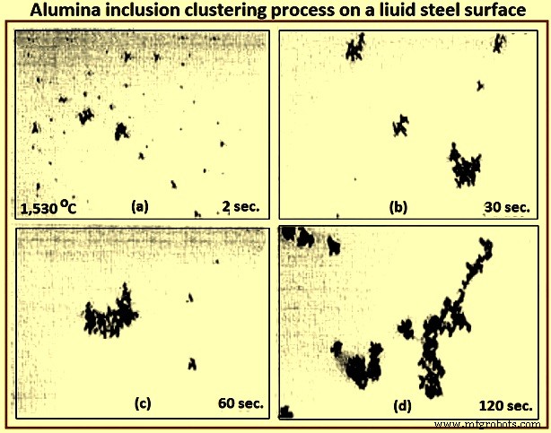
Fig 4 Alumina inclusion clustering process on a liquid steel surface
Electromagnetic visualization (EV) – This Lorentz-force-based detection system is used to accelerate inclusions to the top free surface of the sample of liquid metals and highly conductive opaque fluids. The technique has better resolution than other on-line methods.
Indirect methods
Owing to the cost, time requirements, and sampling difficulties of direct inclusion measurements, steel cleanliness is normally measured in the steel plants using total oxygen, nitrogen pickup, and other indirect methods.
Total oxygen measurement – The total oxygen in the steel is the sum of the free oxygen (dissolved oxygen) and the oxygen combined as inclusions. Free oxygen or ‘active’ oxygen can be measured relatively easily using oxygen sensors. It is controlled mainly by equilibrium thermodynamics with deoxidation elements, such as aluminum. Since the free oxygen does not vary much for example, 3 ppm to 5 ppm at 1,600 deg C for aluminum killed steel. The total oxygen is a reasonable indirect measure of the total amount of oxide inclusions in the steel since there is small population of large inclusions in the steel sample. Hence, the total oxygen content really represents the level of small oxide inclusions only. The total oxygen measured from liquid samples roughly correlates with the incidence of slivers in the product. In particular, tundish samples are normally taken to indicate cleanliness for the cast steel dispositioning.
One of the steel plants needs the total oxygen in the tundish samples less than 30 ppm to ensure shipment of cold-rolled sheet without special inspection. The general conclusions drawn from the data of the total oxygen levels in LCAK steel at each processing step at several steel plants are (i) total oxygen in LCAK steel has steadily decreased with passing years, as new technology is implemented, (ii) plants with RH (Rurhstahl Heraeus) degassing unit achieve lower total oxygen (10 ppm to 30 ppm) than plants with ladle gas stirring (35 ppm to 45 ppm), and (iii) the total oxygen normally drops after every processing step such as 40 ppm in the ladle, 25 ppm in the tundish, 20 ppm in the mould, and 15 ppm in the cast product. Fig 5 shows relationship between total oxygen in tundish and sliver defect index.
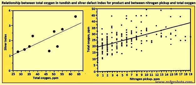
Fig 5 Relationship between total oxygen in tundish and sliver defect index for product and between nitrogen pickup and total oxygen
Nitrogen pickup – The difference in nitrogen content between steelmaking vessels is an indicator of the air entrained during transfer operations. Hence, nitrogen pickup serves as a crude indirect measure of total oxygen, steel cleanliness, and quality problems from reoxidation inclusions. For example, a steel plant restricts nitrogen pickup from ladle to tundish to less than 10 ppm for critical clean steel applications. The oxygen pickup is always many times higher than the measured nitrogen pickup, because of its faster absorption kinetics at the air steel interface. Fig 3 shows relationship between nitrogen pickup and total oxygen. In addition, nitrogen pickup is faster when the oxygen and sulphur contents are low. Hence, for the reduction of the nitrogen pickup, deoxidation is best carried out after tapping. Plant measurements confirm this, as nitrogen pickup reduced from 10 ppm to 20 ppm for deoxidation during tapping to 5 ppm after tapping.
The general conclusion drawn from the data of minimum nitrogen pickup and nitrogen contents measured in LCAK steel at every processing step (except tundish and mould) for several steel plants is that the nitrogen in LCAK steel cast products is around 30 ppm to 40 ppm at the majority of the steel plants. It is controlled mainly by the steelmaking converter or electric furnace operation, but is also affected by secondary steelmaking and shrouding operations. However, the nitrogen pickup is decreasing with passing years, because of new technologies and improved operations. Nitrogen pickup can be normally controlled at 1 ppm to 3 ppm from ladle to the mould. With optimal transfer operations to lessen air entrainment, this pickup can be lowered during steady state casting to less than 1 ppm.
Concentration measurement – For LCAK steels, the dissolved aluminum loss also indicates that reoxidation has occurred. However, this indicator is a less accurate measure than nitrogen pickup since aluminum can also be reoxidized by the slag. The silicon pickup, manganese pickup can be also used to evaluate the reoxidation process.
Lining refractory observation – Analysis of the lining refractory composition evolution before and after operations can be used to estimate inclusion absorption to the lining and the lining erosion. Also, the origin of a complex oxide inclusion can be traced to lining refractory erosion by matching the mineral and element fractions in the slag with the inclusion composition.
Slag composition measurement – Analysis of the slag composition evolution before and after operations can be interpreted to estimate inclusion absorption to the slag. Also, the origin of a complex oxide inclusion can be traced to slag entrpment by matching the mineral and element fractions in the slag with the inclusion composition. However, these methods are not easy because of the sampling difficulties and since changes in the thermodynamic equilibrium are to be taken into account.
Tracer studies for determining exogenous inclusions from slag and lining erosion – Tracer oxides can be added into slags and linings in ladle, tundish, mould, or ingot trumpet, and top compound. Typical inclusions in the steel are then analyzed by SEM and other methods. If the tracer oxides are found in these inclusions, then the source of these inclusions can be decided.
Submerged entry nozzle (SEN) clogging – Short SEN life due to clogging is sometimes an indicator of poor steel cleanliness. The composition of a typical clog during LCAK steel continuous casting consists of Al2O3- 51.7 %, Fe – 44 %, MnO – 2.3 %, SiO2 – 1.4 %, and CaO – 0.6 % , which shows that nozzle clogs are frequently caused by a simultaneous build-up of small alumina inclusions and frozen steel. Hence, SEN clogging frequency is another crude method to evaluate steel cleanliness.
Final product tests
The ultimate measure of cleanliness is to use destructive mechanical tests to measure formability, deep-drawing, and / or bending properties of the final sheet product, or fatigue life of test samples or product samples. Other steel sheet tests include the HIC test and magnetoscopy. Another example is the inclusion inspection method in ultra-sonic fatigue test. These tests are needed to reveal facts such as the potential benefit of very small inclusions (less than 1 micrometer), which are not to be counted against cleanliness.
It can be seen from the above that there is no single ideal method to evaluate steel cleanliness. Some methods are better for quality monitoring while others are better for problem investigation. Hence, it is necessary to combine several methods together to give a more accurate evaluation of steel cleanliness in a given operation.
Since exogenous inclusions can originate from a combination of several sources, methods for their prevention are not likely to be simple. It is only through the correct combination of all these sources and removal mechanisms that the incidence of large inclusions in the steels can be reduced. For the detection of the exogenous inclusions in steel, the methods which are suitable are ultrasonic scanning, microscopic observation, sulphur print, slime (electrolysis), X-ray, SEM, slag composition analysis, and refractory observation.


