Manufaktur industri
Industri Internet of Things | bahan industri | Pemeliharaan dan Perbaikan Peralatan | Pemrograman industri |
home  MfgRobots >> Manufaktur industri >  >> Industrial materials >> bahan nano

Resistive Random Access Memory (RRAM):Tinjauan Material, Mekanisme Switching, Performa, Penyimpanan Sel Multilevel (mlc), Pemodelan, dan Aplikasi

Abstrak

Dalam naskah ini, kemajuan terbaru di bidang teknologi memori akses acak resistif (RRAM) yang dianggap sebagai salah satu teknologi memori yang muncul paling menonjol karena kecepatannya yang tinggi, biaya rendah, kepadatan penyimpanan yang ditingkatkan, aplikasi potensial di berbagai bidang, dan keunggulannya. skalabilitas ditinjau secara komprehensif. Pertama, tinjauan singkat tentang bidang teknologi memori yang muncul disediakan. Sifat material, mekanisme switching resistansi, dan karakteristik listrik RRAM dibahas. Juga, berbagai masalah seperti daya tahan, retensi, keseragaman, dan pengaruh suhu operasi dan kebisingan telegraf acak (RTN) diuraikan. Sebuah diskusi tentang kemampuan penyimpanan sel bertingkat (MLC) dari RRAM, yang menarik untuk mencapai kepadatan penyimpanan yang meningkat dan biaya rendah disajikan. Skema operasi yang berbeda untuk mencapai operasi MLC yang andal beserta mekanisme fisiknya telah disediakan. Selain itu, deskripsi terperinci tentang metodologi switching dan hubungan tegangan arus untuk berbagai model RRAM populer tercakup dalam karya ini. Aplikasi prospektif RRAM ke berbagai bidang seperti keamanan, komputasi neuromorfik, dan sistem logika non-volatile dibahas secara singkat. Artikel ulasan saat ini diakhiri dengan diskusi tentang tantangan dan prospek RRAM di masa depan.

Pengantar

Memori akses acak yang disebut sebagai RAM dapat bersifat volatil atau non-volatil. Memori yang mudah menguap kehilangan data yang disimpan sebelumnya saat melepas catu daya seperti halnya untuk memori akses acak dinamis (DRAM) dan memori akses acak statis (SRAM). Untuk memori non-volatil, konten yang disimpan sebelumnya akan terus disimpan bahkan setelah suplai dihapus. Memori flash adalah contoh khas dari memori non-volatile. Teknologi memori menggabungkan kelebihan dan kekurangan untuk mencapai kinerja yang lebih tinggi, mis. DRAM yang digunakan dalam sistem komputer memiliki kapasitas dan kepadatan yang tinggi, tetapi tidak stabil, artinya ada kebutuhan untuk menyegarkan setiap beberapa milidetik. Karena penyegaran ini, konsumsi energi perangkat meningkat yang tidak diinginkan. SRAM, di sisi lain, cepat tetapi juga mudah berubah seperti DRAM; selain itu, sel SRAM berukuran lebih besar yang menghambat implementasinya dalam skala besar. Memori flash, yang pada dasarnya terdiri dari transistor efek medan semikonduktor-oksida logam (MOSFET) selain gerbang mengambang di setiap sel memori, saat ini digunakan secara luas terutama untuk aplikasi tertanam karena biaya rendah dan kepadatan tinggi. . Tergantung pada bagaimana sel-sel memori diatur, memori Flash diklasifikasikan sebagai NOR Flash dan NAND Flash [1]. Di NOR Flash, sel dibaca dan diprogram secara individual karena terhubung secara paralel ke garis bit. Ini menyerupai koneksi paralel transistor dalam arsitektur gerbang NOR CMOS. Untuk kasus NAND Flash, arsitekturnya menyerupai gerbang NAND CMOS karena sel-selnya dihubungkan secara seri ke garis bit. Harus diperhatikan bahwa lebih sedikit ruang yang digunakan oleh sambungan seri dibandingkan dengan sambungan paralel yang menghasilkan pengurangan biaya NAND Flash. Namun, kedua jenis memori Flash memiliki beberapa kelemahan seperti kecepatan operasi yang rendah (waktu tulis/hapus:1 md/0,1 md), daya tahan yang terbatas (10 6 siklus tulis/hapus), dan tegangan tulis tinggi (> 10 V) [2].

Teknologi memori yang disebutkan di atas, yaitu DRAM, SRAM, dan Flash, adalah memori berbasis penyimpanan muatan. DRAM menyimpan informasi dalam bentuk muatan pada kapasitor, dan SRAM didasarkan pada penyimpanan muatan pada simpul-simpul inverter berpasangan silang, sedangkan teknologi memori Flash menggunakan gerbang mengambang transistor untuk menyimpan muatan. Semua teknologi memori berbasis penyimpanan muatan yang ada saat ini menghadapi tantangan untuk menurunkan skala hingga node 10 nm atau lebih. Hal ini dikaitkan dengan hilangnya muatan yang tersimpan pada skala nano, yang mengakibatkan penurunan kinerja, keandalan, dan margin kebisingan. Selain itu, persyaratan daya dinamis penyegaran yang besar untuk DRAM dan daya bocor untuk SRAM dan DRAM menimbulkan tantangan serius bagi desain hierarki memori di masa mendatang.

Oleh karena itu, kelas memori baru yang biasanya disebut sebagai teknologi memori yang muncul saat ini sedang mengalami pengembangan dan sedang diteliti secara aktif terutama di industri dengan tujuan untuk merevolusi hierarki memori yang ada [3]. Teknologi memori yang muncul ini bertujuan untuk mengintegrasikan kecepatan peralihan SRAM, kepadatan penyimpanan yang sebanding dengan DRAM, dan non-volatilitas memori Flash, sehingga menjadi alternatif yang sangat menarik untuk hierarki memori masa depan.

Untuk mengklasifikasikan perangkat memori sebagai perangkat yang ideal, perangkat tersebut harus memiliki karakteristik sebagai berikut:tegangan operasi rendah (<1 V), ketahanan bersepeda yang lama (>10 17 siklus), waktu penyimpanan data yang ditingkatkan (>10 tahun), konsumsi energi yang rendah (fJ/bit), dan skalabilitas yang unggul (<10 nm) [4]. Namun, hingga saat ini tidak ada satu memori pun yang memenuhi karakteristik ideal ini. Berbagai teknologi memori yang muncul secara aktif sedang diselidiki untuk memenuhi bagian dari karakteristik memori yang ideal ini. Teknologi memori ini yang bergantung pada perubahan resistansi daripada muatan untuk menyimpan informasi adalah sebagai berikut:(i) memori perubahan fase (PCM), (ii) memori akses acak magnetoresistif torsi spin-transfer (STT-MRAM), dan ( iii) memori akses acak resistif (RRAM). Dalam memori perubahan fase, media pensaklaran terdiri dari bahan kalkogenida (umumnya Ge2 -Sb2 -Te5 , GST) [5–7]. PCM bergantung pada perbedaan resistensi antara fase kristal dan fase amorf untuk kemampuan penyimpanan data yang efisien. Fase kristal menunjukkan status resistansi rendah (LRS) atau status ON perangkat sedangkan fase amorf menunjukkan status resistansi tinggi (HRS) atau status OFF. Operasi SET sesuai dengan LRS yang umumnya mengacu pada penyimpanan nilai logika '1', sedangkan operasi RESET sesuai dengan HRS penyimpanan nilai logika '0' di perangkat. Untuk operasi SET, PCM dipanaskan di atas suhu kristalisasinya pada penerapan pulsa tegangan, sedangkan untuk operasi RESET, arus listrik yang lebih besar dilewatkan melalui sel dan kemudian terputus secara tiba-tiba sehingga meleleh dan kemudian memadamkan bahan untuk mencapai keadaan amorf.

Dalam memori akses acak magnetoresistif torsi putaran-transfer, kemampuan penyimpanan disebabkan oleh persimpangan terowongan magnetik (MJT) [8-10], yang terdiri dari dua lapisan feromagnetik dan dielektrik terowongan yang diapit di antara mereka. Arah magnet dari lapisan referensi adalah tetap, sedangkan penerapan medan elektromagnetik eksternal dapat mengubah arah magnet dari lapisan feromagnetik bebas. Jika lapisan referensi dan lapisan bebas memiliki arah magnetisasi yang sama, maka MTJ disebut berada di LRS. Untuk MTJ, untuk berada di HRS, arah magnetisasi dua lapisan feromagnetik adalah anti-paralel. RRAM terdiri dari lapisan isolasi (I) yang diapit di antara dua elektroda logam (M) [11, 12]. RRAM bergantung pada pembentukan dan pemecahan filamen konduktif yang sesuai dengan LRS dan HRS, masing-masing, dalam isolator antara dua elektroda [13-15].

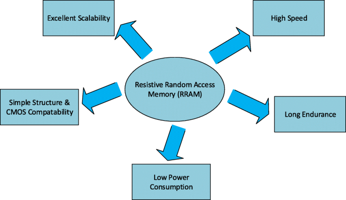
Perbandingan rinci teknologi memori yang ada dan yang muncul ditunjukkan pada Tabel 1. Seperti yang terlihat dari tabel, STT-MRAM dan PCM memiliki keunggulan area yang lebih kecil dibandingkan dengan SRAM. Sementara STT-MRAM menawarkan kecepatan tulis/baca yang cepat, daya tahan yang lama, dan tegangan pemrograman yang rendah, di sisi lain, PCM memiliki kelemahan latensi tulis yang luas. RRAM memiliki tegangan pemrograman yang lebih rendah dan kecepatan tulis/baca yang lebih cepat dibandingkan dengan Flash dan dipandang sebagai pengganti potensial dari memori Flash. Di antara semua kandidat teknologi memori yang muncul, RRAM memiliki keunggulan signifikan seperti fabrikasi yang mudah, struktur metal-insulator-metal (MIM) sederhana, skalabilitas yang sangat baik, kecepatan nanodetik, retensi data yang lama, dan kompatibilitas dengan teknologi CMOS saat ini, sehingga menawarkan keunggulan kompetitif solusi untuk memori digital masa depan [16]. Keuntungan paling signifikan dari RRAM digambarkan pada Gambar 1.

Keuntungan RRAM

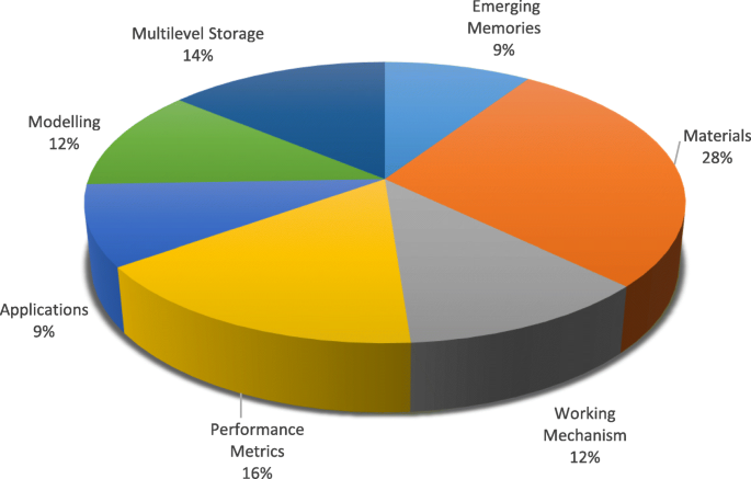
Dalam karya ini, kemajuan terkini dan gambaran rinci tentang teknologi RRAM disajikan. Sebuah tinjauan bahan switching bersama dengan klasifikasi mode switching dan rincian mekanisme switching dibahas di bagian "Memori Akses Acak Resistif (RRAM)". Bagian "Metrik Kinerja Memori Akses Acak Resistif (RRAM)" menyoroti berbagai metrik kinerja RRAM. Karakteristik sel bertingkat (MLC) dari RRAM bersama dengan berbagai skema operasi MLC dan mekanisme fisiknya dianalisis di bagian "Memori Akses Acak Resistif Multilevel (RRAM)". Diskusi rinci tentang pemodelan perangkat RRAM disajikan di bagian "Pemodelan Perangkat RRAM". Di bagian "Aplikasi RRAM" berbagai aplikasi RRAM dibahas. Terakhir, tantangan dan prospek RRAM ke depan disajikan di bagian “Tantangan dan Prospek Masa Depan”. Kategori distribusi makalah yang dikonsultasikan dalam persiapan naskah ulasan ini disajikan pada Gambar. 2.

Distribusi makalah berdasarkan kategori yang dikonsultasikan untuk persiapan tinjauan RRAM

Memori Akses Acak Resistif (RRAM)

Materi Pengalih Resistansi

Telah diamati bahwa di beberapa isolator, perubahan resistansi terjadi di bawah penerapan medan listrik yang diterapkan. Properti perubahan resistensi ini baru-baru ini diselidiki untuk mengembangkan memori non-volatil di masa depan [17]. Fenomena switching resistansi telah diamati dalam berbagai oksida, tetapi oksida logam biner telah dipelajari secara ekstensif sebagai bahan switching yang disukai untuk aplikasi memori non-volatil di masa depan terutama karena kompatibilitasnya dengan pemrosesan CMOS BEOL. Berbagai bahan berbasis oksida logam yang menunjukkan peralihan resistansi non-volatil seperti hafnium oksida (HfO x ) [18–23], titanium oksida (TiO x ) [24–31], tantalum oksida (TaO x ) [32–36], nikel oksida (NiO) [37–40], seng oksida (ZnO) [41–46], seng titanat (Zn2 TiO4 ) [47], mangan oksida (MnO x ) [48, 49], magnesium oksida (MgO) [50], aluminium oksida (AlO x ) [51–53], dan zirkonium dioksida (ZrO2 ) [54-58] telah menarik banyak perhatian dan telah dipelajari secara ekstensif selama beberapa tahun terakhir. Oksida logam ini diendapkan biasanya oleh deposisi laser pulsa (PLD), deposisi lapisan atom (ALD), dan sputtering reaktif. Namun, ALD adalah metode yang disukai secara luas karena kemampuannya untuk secara tepat mengontrol ketebalan dan keseragaman film tipis [59].

Dalam perangkat elektronik konvensional, pemilihan bahan elektroda penting karena mereka bertindak sebagai jalur transportasi untuk pembawa. Untuk RRAM, pemilihan bahan elektroda sangat mempengaruhi perilaku switching perangkat. Misalnya, dalam struktur tembaga/poli(3-heksiltiofena):[6,6]-fenil-C61-butirat metil ester/indium-timah oksida (Cu/P3HT:PCBM/ITO), perilaku switching resistif yang stabil diamati; namun, menghilang setelah elektroda Cu diganti dengan elektroda Pt [60]. Berbagai macam bahan telah digunakan sebagai elektroda untuk RRAM. Bahan elektroda dapat dikelompokkan menjadi lima kategori berdasarkan komposisinya, termasuk elektroda zat dasar, elektroda berbasis silikon, elektroda paduan, elektroda oksida, dan elektroda berbasis nitrit. Elektroda yang paling banyak dan umum digunakan adalah elektroda zat dasar yang meliputi Al [51], Ti[49], Cu[30], graphene [61], karbon nanotube [62], Ag [41], W [36], dan Pt [44]. Untuk elektroda berbasis silikon, tipe-p Si dan tipe-n Si [63] adalah satu-satunya jenis elektroda yang digunakan. Elektroda paduan biasanya menstabilkan perilaku switching resistif dan terutama mencakup Cu-Ti [64], Cu-Te[65], dan Pt-Al [66]. Elektroda berbasis nitrida yang paling umum adalah TiN dan TaN [67, 68]. Elektroda berbasis oksida relatif melimpah, termasuk ZnO yang didoping Al [69], ZnO yang didoping Ga [70], dan ITO [71].

Daftar bahan oksida logam yang telah digunakan baru-baru ini dalam pembuatan perangkat RRAM bersama dengan berbagai kombinasi bahan yang digunakan untuk elektroda atas dan elektroda bawah ditunjukkan pada Tabel 2. Perbandingan rinci dari berbagai parameter juga disajikan. Dari berbagai macam bahan yang digunakan, seseorang dapat memprediksi bahwa pensaklaran resistansi non-volatil banyak diamati pada berbagai jenis oksida. Pilihan material untuk fabrikasi RRAM memberikan keunggulan karena struktur logam oksida logam (MOM) dapat dengan mudah dibuat dengan memanfaatkan oksida yang saat ini digunakan dalam teknologi semikonduktor. Bahan elektroda bawah di RRAM biasanya adalah platinum, yang agak sulit untuk digores. Untuk struktur perangkat tunggal, RRAM dapat berbagi elektroda bawah yang sama sedangkan, untuk arsitektur palang, elektroda bawah terpisah digunakan untuk setiap perangkat. Mereka dapat diperoleh dengan deposisi uap fisik dan lepas landas secara berurutan. Elektroda atas dan lapisan switching resistif diendapkan baik menggunakan deposisi lapisan atom (ALD) atau deposisi uap fisik (PVD).

Mode Pengalihan Resistansi

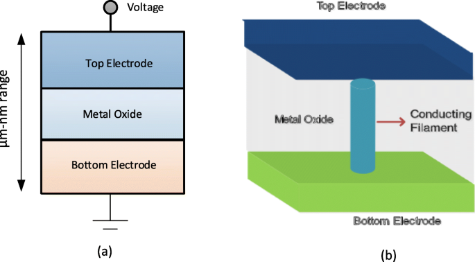
Sebuah memori akses acak resistif (RRAM) terdiri dari sel memori switching resistif yang memiliki struktur logam-isolator-logam yang umumnya disebut sebagai struktur MIM. Strukturnya terdiri dari lapisan isolasi (I) yang diapit di antara dua elektroda logam (M). Tampilan skema dan penampang sel RRAM masing-masing ditunjukkan pada Gambar 3a dan b.

a Skema struktur logam-isolator-logam untuk RRAM. b Tampilan penampang RRAM

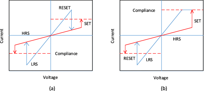
Penerapan pulsa tegangan eksternal di sel RRAM memungkinkan transisi perangkat dari status resistansi tinggi (HRS), atau status OFF yang umumnya disebut sebagai nilai logika '0' ke status resistansi rendah (LRS), atau status ON secara umum. disebut sebagai nilai logika '1' dan sebaliknya. Fenomena switching resistif (RS) dianggap sebagai alasan di balik perubahan nilai resistansi ini dalam sel RRAM. RRAM yang disiapkan awalnya dalam keadaan resistansi tinggi (HRS), untuk mengalihkan perangkat dari HRS ke LRS, penerapan pulsa tegangan tinggi memungkinkan pembentukan jalur konduktif di lapisan switching dan sel RRAM diaktifkan menjadi LRS [72]. Proses yang terjadi karena kerusakan lunak struktur logam isolator logam (MIM) biasanya disebut sebagai 'electroforming' dan tegangan di mana proses ini terjadi disebut sebagai tegangan pembentukan (V f ). Harus dicatat bahwa tegangan pembentukan ditemukan bergantung pada area sel [73] dan ketebalan oksida [74]. Sekarang, untuk mengalihkan sel RRAM dari LRS ke HRS, pulsa tegangan disebut sebagai tegangan RESET (V setel ulang ) diterapkan yang memungkinkan transisi peralihan ini dan prosesnya dirujuk ke proses 'RESET' [75-78]. HRS dari RRAM dapat diubah menjadi LRS pada aplikasi pulsa tegangan. Tegangan di mana transisi terjadi dari HRS ke LRS disebut sebagai tegangan SET (V setel ) dan prosesnya disebut sebagai proses 'SET' [79]. Untuk membaca data dari sel RRAM secara efisien, tegangan baca kecil yang tidak akan mengganggu keadaan sel saat ini diterapkan untuk menentukan apakah sel dalam keadaan logika 0 (HRS) atau logika 1 (LRS). Karena LRS dan HRS mempertahankan nilainya masing-masing bahkan setelah tegangan yang diberikan dihilangkan, RRAM adalah memori yang tidak mudah menguap. Tergantung pada polaritas tegangan yang diberikan, RRAM dapat diklasifikasikan menjadi dua jenis mode switching:(i) switching unipolar dan (ii) switching bipolar [80]. Dalam pensaklaran unipolar, pensaklaran (proses penyetelan dan penyetelan ulang) perangkat antara berbagai keadaan resistansi tidak bergantung pada polaritas tegangan yang diberikan, yaitu pensaklaran dapat terjadi pada penerapan tegangan dengan polaritas yang sama tetapi besarnya berbeda seperti yang ditunjukkan pada Gambar. 4a. Dalam switching bipolar, di sisi lain, switching (proses set dan reset) perangkat antara berbagai status resistansi tergantung pada polaritas tegangan yang diberikan, yaitu transisi dari HRS ke LRS, terjadi pada satu polaritas (baik positif atau negatif) dan polaritas yang berlawanan mengalihkan sel RRAM kembali ke HRS seperti yang digambarkan pada Gambar 4b. Dalam switching unipolar, pemanasan Joule ditafsirkan sebagai mekanisme fisik yang bertanggung jawab untuk memecahkan filamen konduktor selama operasi reset. Dalam switching bipolar, di sisi lain, migrasi spesies bermuatan adalah kekuatan pendorong utama untuk pembubaran filamen konduktif meskipun pemanasan Joule masih berkontribusi untuk mempercepat migrasi. Untuk memastikan, tidak ada kerusakan permanen pada lapisan switching dielektrik selama proses pembentukan/pengaturan RRAM, arus kepatuhan (I cc ) diberlakukan untuk perangkat RRAM. Arus kepatuhan (I cc ) biasanya dipastikan dengan perangkat pemilihan sel (transistor, dioda, resistor) atau oleh penganalisis parameter semikonduktor selama pengujian off-chip.

Kurva I-V untuk RRAM. a Peralihan unipolar dan b pengalihan bipolar [4]

Mekanisme Pengalihan Resistif

Pergantian sel RRAM didasarkan pada pertumbuhan filamen konduktif (CF) di dalam dielektrik. CF adalah saluran yang berdiameter sangat kecil dari orde nanometer yang menghubungkan elektroda atas dan bawah sel memori. Keadaan resistansi rendah (LRS) dengan konduktivitas tinggi diperoleh ketika filamen dihubungkan dan resistansi tinggi (HRS) dihasilkan ketika filamen terputus dengan celah antara elektroda [91]. Berdasarkan komposisi filamen konduktif, RRAM dapat diklasifikasikan menjadi dua jenis berikut:(i) RRAM berbasis ion logam juga disebut sebagai memori akses acak jembatan konduktif (CBRAM) dan (ii) RRAM berbasis filamen kekosongan oksigen yang dirujuk sebagai 'OxRRAM'. Harus dicatat di sini bahwa CBRAM kadang-kadang disebut sebagai memori metalisasi elektrokimia (ECM), sedangkan 'OxRRAM' kadang-kadang juga dikenal sebagai memori perubahan valensi (VCM).

Dalam RRAM berbasis ion logam juga disebut sebagai 'CBRAM', mekanisme fisik yang bertanggung jawab untuk switching resistif didasarkan pada migrasi ion logam dan reaksi reduksi/oksidasi (redoks) berikutnya [92, 93]. Struktur CBRAM terdiri dari elektroda atas (anoda) yang dapat teroksidasi seperti Ag, Cu, dan Ni, elektroda bawah yang relatif lembam (katoda), mis. W, Pt, dan lapisan oksida logam terjepit di antara dua elektroda. Pembentukan filamen dalam sel memori tersebut terjadi karena pelarutan elektroda logam aktif (paling sering Ag atau Cu), pengangkutan kation (Cu + atau Ag + ), dan deposisi atau reduksi selanjutnya pada elektroda dasar inert [94]. Dengan demikian, perilaku pensaklaran resistif jenis RRAM ini didominasi oleh pembentukan dan pelarutan filamen logam.

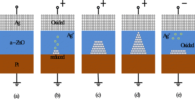
Untuk mendapatkan pemahaman yang lebih baik tentang mekanisme switching CBRAM berbasis ion logam, mari kita perhatikan contoh sel RRAM Ag/a-ZnO/Pt [41]. Sebuah ilustrasi skema umum yang menggambarkan proses switching sel memori akses acak jembatan konduktif ditunjukkan pada Gambar. 5. Keadaan murni dari sel memori CBRAM digambarkan pada Gambar. 5a. Elektroda atas Ag (TE) merupakan komponen aktif dalam pembentukan filamen sedangkan elektroda Pt bawah bersifat inert. Pada penerapan bias tegangan positif ke elektroda atas Ag, oksidasi (Ag → Ag + + e ) terjadi di elektroda atas karena Ag + kation dihasilkan dan diendapkan ke dalam lapisan dielektrik (a-ZnO) dari elektroda Ag. Bias negatif pada elektroda bawah Pt (BE) menarik Ag + kation, dan dengan demikian, reaksi reduksi (Ag + + e → Ag) terjadi pada elektroda bawah. Jadi, Ag + kation direduksi menjadi atom Ag dan terakumulasi sampai jembatan penghantar terbentuk (Gbr. 5b-d) dan perangkat RRAM dikatakan menunjukkan LRS. Proses ini disebut sebagai 'SET'. Ketika polaritas tegangan yang diberikan dibalik, filamen konduktor tinggi larut hampir sepenuhnya dan perangkat dikatakan dalam keadaan resistansi tinggi (HRS). Proses ini disebut sebagai 'RESET' dan digambarkan pada Gambar 5e.

Skema mekanisme switching RRAM jembatan konduktif. a Keadaan murni perangkat RRAM. b , c Oksidasi Ag dan migrasi Ag + kation menuju katoda dan reduksinya. d Akumulasi atom Ag dan elektroda Pt menyebabkan pertumbuhan filamen yang sangat konduktif. e Pembubaran filamen terjadi pada penerapan tegangan polaritas yang berlawanan [41]

Dalam RRAM berbasis kekosongan oksigen (OxRRAM), mekanisme fisik yang bertanggung jawab untuk switching resistif umumnya dikaitkan dengan pembangkitan kekosongan oksigen (V \(_{o}^{2+}\)) dan selanjutnya relokasi ion oksigen (O 2− ), sehingga memungkinkan pembentukan filamen konduktif antara elektroda atas dan bawah sel RRAM [59]. Awalnya, untuk sel RRAM yang dibuat, proses pembentukan, yaitu pemecahan lembut dielektrik sangat penting. Setelah kerusakan dielektrik lunak terjadi, atom oksigen terlempar keluar dari kisi pada penerapan medan listrik tinggi menuju antarmuka anoda dan menjadi ion oksigen (O 2− ) sedangkan kekosongan oksigen (V \(_{o}^{2+}\)) tertinggal di lapisan oksida. Ion oksigen (O 2− ) bereaksi dengan bahan anoda atau dilepaskan sebagai oksigen non-kisi netral, jika logam mulia digunakan sebagai bahan anoda untuk membentuk lapisan oksida antarmuka. Dengan demikian, antarmuka elektroda / oksida berperilaku seperti 'reservoir oksigen' [85]. Selanjutnya, akumulasi kekosongan oksigen (V \(_{o}^{2+}\)) dalam oksida curah mengalihkan sel RRAM ke status resistansi rendah (LRS) saat filamen konduktif (CF) terbentuk dan arus yang cukup besar mengalir di perangkat. Untuk mengalihkan perangkat kembali ke status resistansi tinggi (HRS), proses reset terjadi selama ion oksigen (O 2− ) bermigrasi kembali ke oksida curah dari antarmuka anoda dan bergabung dengan kekosongan oksigen (V \(_{o}^{2+}\)) atau untuk mengoksidasi endapan logam CF dan dengan demikian sebagian memecah filamen, sehingga mengubah kembali sel RRAM menjadi HRS. Untuk sel RRAM yang menunjukkan mekanisme switching unipolar, difusi ion oksigen (O 2− ) diaktifkan secara termal oleh arus pemanasan Joule dan dengan demikian ion oksigen berdifusi dari antarmuka atau daerah sekitar CF karena gradien konsentrasi. Juga, harus dicatat bahwa arus reset yang relatif lebih tinggi diperlukan dalam RRAM switching unipolar untuk menaikkan suhu lokal di sekitar CF. Dalam RRAM switching bipolar, di sisi lain, ion oksigen (O 2− ) perlu dibantu oleh medan listrik terbalik karena lapisan antarmuka dapat menghadirkan penghalang difusi yang signifikan dan difusi termal murni tidak cukup. Harus dicatat bahwa ruptur parsial CF terjadi pada kedua kasus, mengalihkan sel RRAM ke status resistensi tinggi (HRS). Hal ini terutama disebabkan oleh pembentukan kekosongan oksigen (V \(_{o}^{2+}\)) dan daerah miskin menghasilkan celah tunneling untuk elektron. Untuk mengalihkan perangkat kembali ke LRS (proses SET), CF menghubungkan kembali elektroda sebagai akibat dari kerusakan lunak di wilayah celah. Proses set/reset serupa dapat berulang untuk banyak siklus.

Berdasarkan pembahasan di atas, CBRAM juga dikenal sebagai electrochemical metallization memory (ECM) mengandalkan elektroda logam yang aktif secara elektrokimia seperti Ag, Cu, atau Ni untuk membentuk CF berbasis kation logam [95]. CF dalam kekosongan oksigen RRAM berbasis filamen 'OxRRAM' juga dikenal sebagai memori perubahan valensi (VCM) terdiri dari cacat kekosongan oksigen, bukan atom logam, karena migrasi anion dalam bahan penyimpanan itu sendiri [96]. Meskipun mekanisme switching dari kedua 'OxRRAM' dan 'CBRAM' dibahas secara rinci, masih ada beberapa perdebatan tentang mekanisme switching dari kedua jenis RRAM [97]. Misalnya, di mana CF mulai tumbuh dalam proses set dan di mana pecah dalam proses reset, dan bagaimana kekosongan oksigen/atom logam ini berkumpul untuk membentuk CF. Karakteristik tegangan arus (I-V) dari 20 siklus pensaklaran berurutan Ta/TaO x /Pt [98] berbasis struktur RRAM diselidiki, dan variasi yang jelas dari kedua LRS dan HRS untuk siklus switching berturut-turut diamati. Akibatnya, jendela memori keseluruhan menurun, menurunkan kinerja RRAM secara keseluruhan. Variabilitas resistensi siklus-ke-siklus ini terutama dikaitkan dengan pembentukan acak CF serta pecahnya masing-masing selama operasi set dan reset.

Perbandingan OxRRAM dengan CBRAM berdasarkan berbagai parameter operasional ditunjukkan pada Tabel 3 [81, 84, 86-88, 99, 100]. Perbandingan ini mengungkapkan perbedaan mencolok dalam hal karakteristik daya tahan dari jenis memori RRAM ini. Perbedaan ini disebabkan karena filamen penghantar CBRAM terutama terdiri dari atom logam yang relatif lebih mudah hanyut dan berdifusi dibandingkan dengan kekosongan oksigen, sehingga menyebabkan penurunan waktu retensi dan karakteristik daya tahan CBRAM dibandingkan dengan OxRRAM. Meskipun mekanisme switching dari kedua jenis RRAM berbeda, ada banyak kesamaan karakteristik di antara keduanya. Satu-satunya perbedaan yang signifikan adalah ketahanan OxRRAM secara signifikan lebih tinggi daripada CBRAM.

Metrik Kinerja Resistive Random Access Memory (RRAM)

Ketahanan

Memori akses acak resistif melibatkan transisi yang sering antara status resistansi tinggi (HRS) dan status resistansi rendah (LRS). Setiap peristiwa switching antara keadaan resistif dapat menyebabkan kerusakan permanen dan menyebabkan penurunan kinerja RRAM. Daya tahan dengan demikian didefinisikan sebagai berapa kali perangkat RRAM dapat dialihkan antara HRS dan LRS sambil memastikan rasio yang dapat dibedakan secara andal di antara mereka [101]. Dengan demikian, tes daya tahan menentukan jumlah maksimum siklus set/reset yang dapat diaktifkan secara efektif sebelum HRS dan LRS tidak lagi dapat dibedakan. Karakteristik daya tahan RRAM diperoleh dengan melakukan urutan sapuan I-V dalam sel switching resistif dan ekstraksi berikutnya R SDM dan R LRS pada penerapan tegangan baca (biasanya 0,1 V) [41]. Metode ini dapat diandalkan karena seseorang dapat memperoleh pergantian perangkat yang benar dalam setiap siklus; namun, metode ini sangat lambat karena waktu yang dibutuhkan untuk mendapatkan sapuan IV bisa sangat tinggi terutama jika melibatkan arus yang lebih rendah.

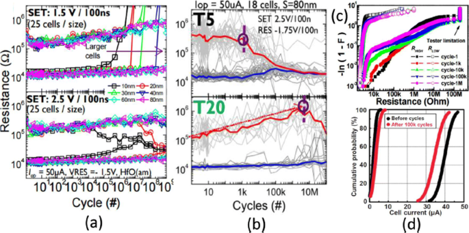
Siklus daya tahan dalam H f O x Sel RRAM menunjukkan ketergantungan yang kuat pada ukuran sel, seperti yang digambarkan pada Gambar. 6a, di mana daya tahan yang lebih baik dalam perangkat RRAM dengan ukuran sel yang lebih besar dilaporkan. Selain itu, pengurangan ketebalan lapisan secara vertikal menghasilkan penurunan kinerja daya tahan untuk tegangan SET pada 2,5 V seperti yang ditunjukkan pada Gambar 6b ​​[102]. Penurunan kinerja daya tahan dengan penurunan lapisan switching ini adalah akibat dari berkurangnya jumlah ion di wilayah aktif. H f O x -RRAM berbasis menunjukkan kinerja ketahanan yang sangat baik 10 6 siklus pada larik 1-kb dengan ukuran sel 30-nm di bawah 0,18 μ m teknologi dan hal yang sama ditunjukkan pada Gambar. 6c [103]. Dengan menambahkan lapisan ekstra A l O x di atas elektroda bawah (BE), stabilitas susunan dapat ditingkatkan lebih lanjut karena kekebalan gangguan baca untuk HRS meningkat. Untuk T a O x -berbasis RRAM, penurunan kinerja daya tahan dengan meningkatnya lebar pulsa dan amplitudo tegangan RESET diamati pada Ta/Ta2 O5 / Struktur RRAM TiN [105]. Perbandingan elektroda bawah TiN dan Ru pada Ta/Ta2 O5 /TiN RRAM menunjukkan bahwa penyebab utama penurunan daya tahan adalah karena reaksi ion oksigen dengan elektroda TiN. Selanjutnya, peningkatan daya tahan 10 9 siklus switching diperoleh tanpa verifikasi dalam struktur RRAM serupa dengan mengurangi Ta2 O5 lapisan ke 3 nm [106] dan penggunaan pulsa segitiga yang memiliki lebar <5 ns. Untuk kinerja larik skala besar, perbandingan Ta 2-Mb2 O5 memori sebelum dan sesudah 10 5 siklus uji ketahanan ditunjukkan pada Gambar. 6d [104]. Distribusi arus sel menunjukkan variasi kecil untuk siklus awal dan akhir. Juga, arus sel untuk LRS turun di bawah 50 μ A, menunjukkan konsumsi daya array yang rendah. Perangkat switching resistif dengan daya tahan lebih tinggi dari 10 12 cycles have been reported in different types of RRAM cells involving tantalum oxide (TaO x )-based switching mediums [32, 36, 59]. Thus, tantalum oxide-based RRAM devices seem to be exhibiting the highest endurance.

a Endurance cycles of H f O x -based RRAM at different SET voltage and cell size b with different thickness (T5=2 nm, T20=10 nm) at 2.5 V set voltage. c Resistance distribution of 1-kb array obtained from Weibull plots under different endurance cycles. d 100 k cycles endurance of 2-Mb-Ta2 O5 -based array; Reprinted from refs [102–104]

Retention

The data retention of a RRAM device involves investigating stability over a period of time for both LRS and HRS after undergoing set and reset transitions. In other words, the time period for which a memory cell will remain in a particular state after the set/reset operation determines the capability of a memory cell to retain its content [11]. The application of the constant voltage stress (CVS) over time using a low read voltage (0.1 V) and the measurement of the current versus time (I-t) curve for both LRS as well as the HRS enables the measurement of state retention. Due to the dispersing nature of atomic rearrangements induced in RRAM because of set voltage, the long retention time in LRS is difficult to obtain whereas, in HRS, retention is not a concern as it is usually the natural state of the device and RRAM will continue to remain in this state if no bias (or low bias) is applied. The retention in the LRS depends on the compliance limit during the SET transition, e.g. in RRAMs based on conductive filament switching mechanism, the larger compliance current produces a stronger conducting filament which is more stable over time [28, 41], as compared to a smaller compliance current. A projected endurance of 10 years at 85 C has been demonstrated in Ti/HfO2 /TiN [18]. A commonly used method to obtain device endurance is by applying read pulse at high temperature after certain time intervals (e.g. every 1 s) and extrapolate the resistance to a 10-year period. Although this method is easy to implement, it has certain limitations primarily due to the read voltage stress applied to the cell. An alternative method is to change the temperature and record the time until the device fails. Activation energy is extracted by plotting the Arrhenius plot and extrapolate down to the operating temperature. However, the limitation of this method is that waiting is necessary until the failure occurs in the RRAM cell, and thus, this method is more time-consuming and expensive.

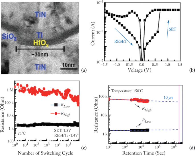
The device characteristics of H f O x -based RRAM [81, 103] developed at the Industrial Technology Research Institute, Taiwan, are demonstrated to further understand the working of RRAM device. The transmission electron microscopy (TEM) image of the TiN/Ti/ H f O x /TiN RRAM device with 30-nm cell size is shown in Fig. 7a. The device exhibits bipolar switching characteristics and the I-V curve obtained at 200 μ A set compliance current is shown in Fig. 7b. The device presents endurance of 10 6 switching cycles with the resistance on/off ratio greater than 100 at set/reset programming conditions of + 1.5 V/– 1.4 V pulse with 500 μ s pulse width and the same is depicted in Fig. 7c.

a Transmission electron microscopy (TEM) image of TiN/Ti/HfO x /TiN RRAM device. b Typical current-voltage (I-V) characteristics of the device with 30-nm cell size. c 10 6 endurance switching cycles obtained from 500 μ s pulse. d A retention lifetime of 10 years is expected by testing at 150 C; reprinted from refs. [81, 103]

Uniformity

In RRAM cell, poor uniformity of various device characteristics is one of the significant factors limiting the manufacturing on a wider scale. The switching voltages, as well as both the HRS and the LRS resistances, are among the parameters exhibiting a high degree of variation. The variations of the resistance switching include temporal fluctuations (cycle-to-cycle) and spatial fluctuations (device-to-device). The stochastic nature of the formation and rupture of conductive filament is believed to be the main reason for these variations. Cycle-to-cycle and device-to-device variability is a major hindrance for information storage in RRAM devices [59]. The observation of cycle-to-cycle variability is influenced by the change in the number of oxygen vacancy defects that arise in the CF due to its stochastic nature of formation and rupture during the switching event [107]. Due to this random nature of the CF, the prediction and the precise control of the shape of the CF becomes extremely challenging. This variability becomes worse as the compliance limit (i.e. compliance current ‘I cc ’) is reduced. On the other hand, for the higher value of ‘I cc ’, the ratio of standard deviation (σ ) and average resistance (μ ) is low, resulting in a smaller LRS resistance spread. This is attributed to the higher defects in the CF, thus forming a well-defined path for current conduction.

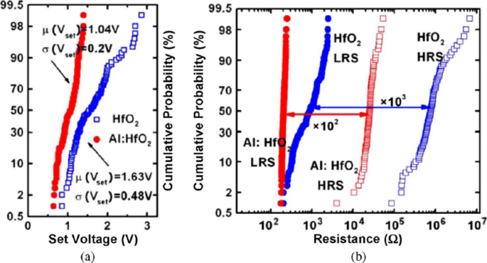
RRAM also exhibits device-to-device (cell-to-cell) non-uniformity which also degrades the memory performance by reducing the memory margin between two states. The origin of this variability is attributed to the non-uniformities in the fabrication process such as the thickness of the switching film, etching damages and surface roughness of the electrodes. A lot of research has been conducted to improve the uniformity of RRAM and several methods have been explored for the same. One of the methods utilizes the concept of inserting nano-crystal seeds which confine the paths of the conductive filament by enhancing the effect of local electric field [82, 90, 108]. In Ti/TiO 2−x /Au-based RRAM [28], the induction of platinum (Pt) nano-crystals within the thin TiO 2−x results in an enhanced uniformity of the RRAM cell. The Pt nano-crystals limit the switching effect into regions with high oxygen vacancy generation probability which results in improved uniformity. In another approach, engineering the electrode/oxide interface by embedding appropriate buffer layers is very useful in achieving uniform RRAM operation. In HfO x -based RRAM [109], a thin Al buffer layer is inserted between the TiN electrode and HfO x oxide layer. This results in significant improvement of set voltage distribution as well as the resistance distribution, thus enhancing the uniformity of the device. The improvement in the SET voltage and the resistance distribution of the RRAM device after inserting a thin Al buffer layer between TiN electrode and HfO x bulk oxide and the same is depicted in Fig. 8 [59]. Al atoms are assumed to diffuse into HfO2 thin films, and they tend to localize oxygen vacancies due to the reduced oxygen vacancy formation energy, thus stabilizing the generation of conductive filaments, which helps to improve the resistance switching uniformity.

Uniformity improvement of Al buffered HfO x RRAM compared to HfO x -based RRAM array. a Statistical distribution of SET voltage (V set ) obtained from 100 DC sweep cycles. b HRS and LRS statistical distribution for 100 pulse sweep cycles; reprinted from ref. [59]

In addition to the materials engineering approach, a novel programming method has also been suggested to reduce fluctuations. A multistep forming technique was implemented in W/HfO2 /Zr/TiN [22]-based RRAM to minimize the overshoot current due to the parasitic effects. A multi-step forming technique results in the gradual formation of the filament; thus, a low set/reset current is achieved improving the switching characteristics of the device. Various other methods such as constant voltage forming and hot forming (usually referred to as forming at a higher temperature) have also been investigated to effectively reduce the resistance variations [110]. Another method of achieving high uniformity is by applying a pulse train rather than a single pulse to a RRAM cell [23]. This approach not only results in improved uniformity but also enhances the multilevel capability of a RRAM cell.

Effect of Operating Temperature and Random Telegraph Noise

To achieve a reliable performance of the RRAM device, the effect of operating temperature and random telegraph noise (RTN) is investigated. It is observed that the resistance of both the LRS and HRS states undergoes variations because of the change of operating temperature. The temperature study of TiN/HfO2 /Ti/TiN [111] was carried out. A positive sweep voltage of <3 V magnitude and compliance current of 1 μ A was applied for the electroforming. Once forming takes place, a reset voltage (V setel ulang ) <–1 V switches the device back to the HRS (OFF state). To switch the device back to the LRS (ON state), set voltage (V set ) <1 V is applied.

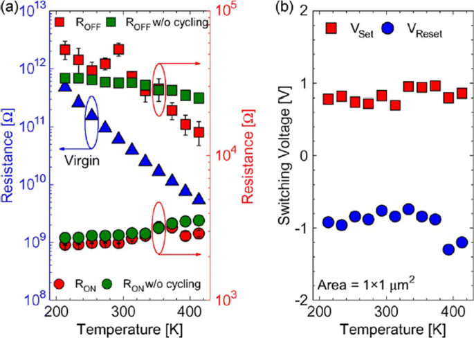
The reset operation in RRAM device tends to show voltage-controlled negative differential resistance (NDR). The reset operation occurs abruptly at low temperatures, while for temperatures above room temperature, the reset process takes place more gradually. The resistance of the RRAM device in the pristine state, as well as the ON state and OFF state as a function of temperature is depicted in Fig. 9a. The semiconducting behavior is observed for the pristine state as well as the OFF state, i.e. resistance decreases with increase of temperature. For the ON state, a metallic characteristic is observed, i.e. resistance increases with increase of temperature. Due to the variation of resistance with change in temperature, R OFF /R ON also decreases from a value of 20 to approximately 5 over the temperature range of 213–413K. In Ti/HfO x /Pt devices, decrease in R OFF /R ON was observed with temperature-dependent cycling. This decrease in resistance ratio was attributed to the built-up of oxygen-vacancy-related traps inside the HfO2 metal oxide layer [112, 113]. Additionally, temperature-dependent measurements without set/reset operation were carried out to evaluate the impact of I-V cycling on the R OFF /R ON perbandingan. The sweep voltage across the RRAM device was stopped before reaching V set dan V setel ulang nilai-nilai. For OFF state resistance (green rectangles), a weaker temperature dependence was observed in contrast to the ON state resistance (green circles) which exhibited similar characteristics, compared to the cycling case. From these observations, we infer that I-V cycling induces stronger temperature dependence, which decreases the R MATI /R AKTIF perbandingan. The effect of temperature variation on the switching voltages V set dan V setel ulang is depicted in Fig. 9b. The slight variation in V set with changing temperature indicates that there is no significant temperature difference. For the case of V setel ulang , the general trend is that a decrease in voltage value of about 0.2 V with temperature increase in the range of 233–333K is observed. Also, a slow increase of V setel ulang is observed for 353–413K temperature range.

The effect of varying temperature on a virgin resistance (left axis) and the OFF-state as well as the ON-state resistances (right axis) at 213–413K temperature range and b switching voltages V set dan V setel ulang; reprinted from ref. [111]

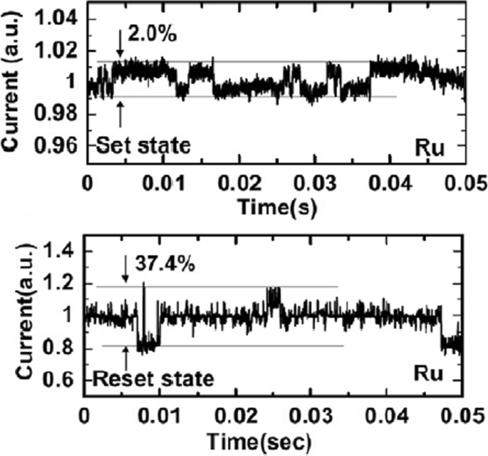
Random telegraph noise (RTN) is another factor that affects the performance of RRAM. RTN has for long been used as an indicator of device performance and reliability. RTN decreases the memory margin between the HRS and LRS because of the extensive fluctuations in the read current during the read operation. Due to the effect of RTN, the read margin, scaling potential and the multilevel cell capability of a RRAM cell are greatly affected [114]; thus, it needs to be investigated to achieve reliable performance. To investigate the effect of bottom electrode on RTN, an analysis of Ta2 O5 /TiO2 RRAM [115] was carried out. The examples of complex RTN signals in LRS and HRS are depicted in Fig. 10. RTN causes read instability in the RRAM device, thus reducing the read margin, multibit storage implementation and hindering device scaling. The RTN is attributed to the trapping and de-trapping of electrons in the proximity of the CF in LRS whereas it occurs in the tunneling gap in the HRS state. Although the physics of RTN is still not clear and is being highly debated, the electron trapping and de-trapping which temporarily inhibits the charge transport is widely accepted as the mechanism responsible for fluctuation due to RTN. It is observed that with the decrease in operation current, the amplitude of RTN increases, thus highly affecting the HRS level. Therefore, it is necessary to ensure the additional resistance margin to achieve reliable performance. RTN in RRAM has been researched extensively, although the physical mechanism of RTN is still not explicitly defined. RTN can be utilized as a tool to map the movements of active vacancies in RRAM due to its time-dependent variation. This might be quite useful to understand the failure mechanisms of other reliability issues.

Complex RTN signals in LRS and HRS of Ta2 O5 /TiO2 -based RRAM depicting normalized noise amplitude and average current; reprinted from ref. [114]

Multilevel Resistive Random Access Memory (RRAM)

Multilevel Per Cell (mlc) Storage

Owing to their small physical size and low power consumption, RRAM devices are potential for future memory and logic applications. Increased storage density is among the most critical aspects of memory technology to enable the design of multibit capacity [89] memory cells. The multiple resistive states can be achieved in RRAM cells which provide benefits of low-cost and high-density non-volatile data storage solutions. Currently, a lot of research is being conducted in the area of RRAM to scale down the dimensions and increase the structural density of memory arrays. Previously, the storage density of RRAM has been increased by the reduction of device size; however, the complexity involved in the experimental procedures limits its successful implementation. Another suggested method is employing three-dimensional (3D) crossbar architectures. Two types of architectures of ‘vertical’ and ‘crossbar RRAM’ have been proposed [116, 117]; however, both these architecture types require advanced fabrication procedures which is not desirable. A much simpler alternative to increase storage density in RRAM devices is by making use of multilevel cell (MLC) storage technology which enables storing more than one bit per cell without reducing the physical device dimensions. This MLC is one of the most promising properties of RRAM which can significantly increase the memory storage density [83, 118–125]. Thus, instead of a single high and low resistance state (HRS and LRS), we can achieve multiple HRS and LRS, without changing the device dimensions. However, to achieve reliable MLC operation, the precise control over the resistance of the different resistance levels of RRAM should be ensured; otherwise, the device will suffer from resistance variability and reliability issues mainly due to the random nature of the conductive filament formation during the switching process [126].

Methods to Obtain Multilevel Per Cell (mlc) Modes in RRAM

The MLC behavior in RRAM makes it very useful for high-density applications. To obtain MLC behavior in RRAM, the following three methods are employed:(i) changing compliance current, (ii) controlling reset voltage and (iii) varying pulse width of program/erase operation.

MLC by Changing Compliance Current

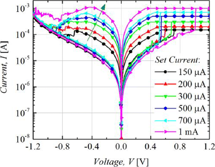
The RRAM device is usually operated with 1-RRAM (1R) cell configuration [41] or in 1-Transistor 1-RRAM (1T-1R) cell configuration [18]. The MLC characteristics in 1R configuration can be obtained by changing the current compliance (I cc ) during ‘set’ operation whereas the MLC characteristics in 1-Transistor 1-RRAM (1T-1R) cell structure are controlled by varying the voltage at the gate of the transistor, which enables the control of compliance current (I cc ) during the set operation of a RRAM cell. The typical MLC I-V curves of Ti/Ta2 O5 /Pt [127] based RRAM cell are shown in Fig. 11. As the compliance current (I cc ) is increased from 150 μ A to 1 mA, six different LRS are obtained at I cc =150 μ A, I cc =200 μ A, I cc =300 μ A, I cc =500 μ A and I cc =700 μ A, I cc =1 mA due to the increase in the respective current of LRS (I LRS ) while the HRS is maintained constant and the HRS current (I HRS ) remains same for all the LRS levels. For Ti/Ta2 O5 /Pt RRAM, with the increase in I cc , the maximum reset current (I reset ) also increases while the set voltage is almost maintained constant. Also, it was observed that the resistance of the LRS (R LRS ) decreases while the (I reset ) increases owing to the stronger filament formation with the increase in I cc .

Multilevel characteristics of Ti/Ta2 O5 /Pt RRAM obtained by controlling the compliance current. ‘Reproduced from [127], with the permission of AIP Publishing’

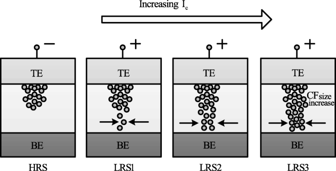
The formation of the CF and its corresponding widening with an increase in I cc is the attributed mechanism of multilevel per cell (MLC) in compliance current (I cc ) mode as depicted schematically in Fig. 12. With an increase in the size of CF because of an increase of I cc , the resistance of the CF decreases and hence results in multiple LRS levels for different values of I cc . It is also observed that I reset increases with increasing I cc as higher power is required to rupture the CF having larger diameter.

Schematic illustration of multiple resistance states in RRAM cell obtained by varying compliance current ‘I cc ’ [98]

MLC by Controlling Reset Voltage

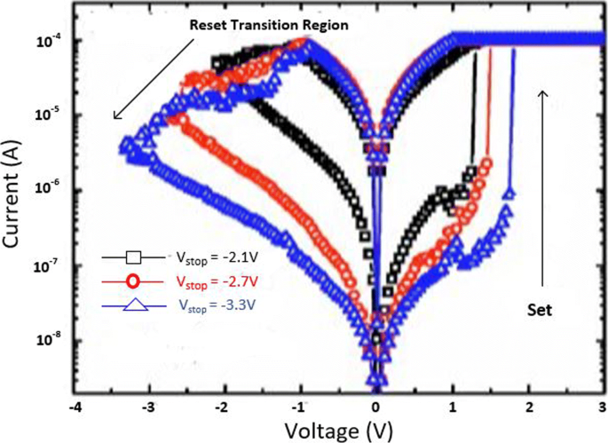
The MLC characteristics in a RRAM cell can also be obtained by controlling the reset voltage (V setel ulang ) while (I cc ) is maintained constant. In this case, the typical MLC I-V curves of TiN/HfO x /AlO x /Pt-based RRAM cell [128] by applying different (V setel ulang ) of − 2.1 V, − 2.7 V and − 3.3 V are shown in Fig. 13.

Multilevel characteristics of TiN/HfO x /AlO x /Pt RRAM obtained by controlling the reset voltage. ‘Reproduced from [128], with the permission of AIP Publishing’

It is observed that with an increase in (V setel ulang ), the HRS current (I HRS ) decreases; thus, multiple HRS levels with the same LRS resistance are obtained. In addition, the set voltage (V set ) also increases as V setel ulang is increased while as the I setel ulang remains almost constant.

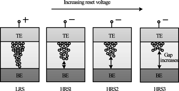
The decrease in I HRS with the increase in reset voltage is primarily due to the increase in the gap between the metal electrode and tip of the CF as depicted in Fig. 14. The more the magnitude of the V setel ulang , the larger the gap and thus the higher the value of resistance. Therefore, an increase in the gap between the CF tip and bottom electrode (BE) with increasing reset voltage results in multiple resistance levels of HRS. It is observed that the devices in which the I setel ulang shows a gradual change in current instead of the abrupt change during the ‘reset’ operation, the change in HRS resistance in such devices can be due to decrease in the size of the conductive filament (CF) as V setel ulang is increased. This approach is more viable practically for cross-point architectures as it requires relatively lower complex circuitry.

Schematic illustration of multiple resistance states in RRAM cell obtained by varying reset voltage ‘V reset ’ [98]

MLC by Varying Program/erase Pulse Width

MLC characteristics can also be obtained by varying the program/erase pulse width while the amplitude of the pulse is maintained constant [23]. In HfO x -based RRAM [128], three HRS levels were demonstrated by varying the width of the reset pulse from 50 ns to 5 μ S. This method of obtaining MLC characteristics in RRAM is relatively easier; however, this scheme is energy inefficient. This drawback limits the application of this method to obtain reliable characteristics in the RRAM cell. The higher energy consumption of the RRAM device was confirmed on the comparison of the transient responses between the reset pulse amplitude and pulse width control. This is particularly due to the higher unwanted energy dissipation as the thermal energy in the resistive switching material.

A summary of RRAM devices exhibiting multiple resistance states is shown in Table 4. As is evident from the table, various RRAM devices with multiple resistance states have been reported. Till date, however, only 8 resistance states have been demonstrated in a single RRAM cell either by varying I cc or V setel ulang . Therefore, there is a huge scope for increasing the number of resistance states in the RRAM cell, thus enhancing its storage density.

Modeling of RRAM Devices

Modeling plays a very critical role in development of devices utilizing semiconductor technologies. To fully understand device operation and to optimize the performance, an accurate model is of great importance. A number of RRAM models with varying features and accuracy have been proposed [129]. This section discusses the characteristics and attributes of the various commonly used RRAM models popular.

Stanford/ASU Model

One of the most popular physics-based RRAM models is the Stanford/ASU RRAM model [130–132], proposed by Guan et al. and Chen et al. This model was applied to validate the I-V switching characteristics of HfO2 RRAM [128] and includes the effect of Joule heating and temperature change on the switching of RRAM devices.

This model is dependent on the CF growth inside a dielectric switching layer. The filament gap, i.e. the gap between the tip of the CF and top electrode, is the internal state variable for this model. The growth of CF inside a dielectric is attributed to the oxygen ion movement and regeneration and recombination of oxygen vacancies [133]. Thus, the rate of change of filament gap (g) is given as [130]:

$$ {\frac{dg}{dt}} =V_{\tiny{0}}.\exp\bigg({{\frac{-E_{a},m}{k_{b}.T}} }\bigg). {\text{Sinh}} \bigg({\frac{qa_{h}\gamma V}{L.k_{b}.T}}\bigg) $$ (1)

dimana E a is the activation energy, V is the magnitude of the voltage applied across the device, L is the switching material thickness, a h is the hopping distance, γ is the local field enhancement factor, V 0 is the velocity containing attempt to escape frequency, K b is the Boltzmann constant, q is the elementary unit charge and T is the temperature of the conductive filament.

The spatial variation in the gap size is accounted for in this model, in addition to the variations which arise due to the stochastic property of the ion process. A noise signal is added to the gap distance to account for these variations as [130]:

$$ g_{|t+\Delta t} =F \Big[ g_{|t}, {\frac{dg}{dt}} \Big] + \delta_{g}\times\tilde{X}(n)\Delta t, n ={\frac{t}{T_{GN}}} $$ (2)

dimana Δ t is the simulation time step, the function F represents time evolution of gap size fromt to Δ T. \(\tilde {X}\)(n) is a zero mean Gaussian noise sequence. T GN is the time interval after which \(\tilde {X}\)(n ) changes to next random value.

The variation in the gap size δ g depends on kinetic energy of ions and filament temperature as [130]:

$$ \delta_{g} (T) ={\frac{\delta^{\tiny{0}}_{g}}{\bigg\{ 1+\exp \Big({\frac{T_{\text{crit}}- T}{T_{\text{smith}}}} \Big) \bigg\}}} $$ (3)

where \(\delta ^{0}_{g}\) and T smith are fitting coefficients to match the resistance distribution curves to experiments and T kritik is a threshold temperature above which the gap size changes significantly.

This model shows strong dependence on temperature; thus, there is a need to account for the change of ‘T’ . With change in cell characteristics, the dynamic inner domain temperature T changes significantly, while the outer domain assumed to be at uniform and stable temperature (T bath ), is related as [130]:

$$ c_{p} {\frac{dT}{dt}} =V(t).I(t) - k(T-T_{\text{bath}}) $$ (4)

where C p is the effective heat capacitance of inner domain, V (t) I (t) represents the Joule heating and k is the effective thermal conductivity.

Using a generalized conduction mechanism, the current conduction is defined as [130]:

$$ I(g,v) =I_{\tiny{0}}.\exp\bigg({{\frac{-g}{g_{\tiny{0}}}} }\bigg){\text{Sinh}} \bigg({\frac{V}{V_{\tiny{0}}}}\bigg) $$ (5)

dimana Aku 0 , g 0 dan V 0 are the fitting parameters to match experimental results.

One of the significant features of this model is its implementation in neuromorphic applications and RRAM synaptic device design [134], giving the model a great degree of flexibility and further scope for implementation in various neuromorphic systems.

Physical Electro-thermal Model

Physical electro-thermal model was developed by Kim et al. [135] and implemented with tantalum pentoxide (Ta2 O5 ) -based bilayer RRAM [136–138]. This physical model solves the differential equations based on finite element solving method. This model also makes use of electrothermal physics phenomenon approach for modeling [139], thus giving it advantage in terms of flexibility to incorporate finite element method (FEM) solver to simulate the system very accurately. However, the drawback of this approach is its difficulty in implementation for SPICE and Verilog circuit solvers.

This model describes CF as a doped region having oxygen vacancies as dopants with CF extending from the top to the bottom electrode of the device. To describe the drift-diffusion of vacancy migration, this model assumes the same equation can be used to describe both the processes of oxygen ions and vacancies. The ion model by Mott and Gurney [140] is employed here to describe the process given as [135]:

$$ {\frac{dn_{D}}{dt}} =\Delta \times \bigg(D_{s}.\Delta_{n\tiny{D}}- \mu v n_{D} \bigg) + G $$ (6)

dimana D s describes the diffusion process, v gives the drift velocity of vacancies and G is the CF growth rate which actually describes the SET process. The parameters are defined as [135]:

$$ D_{s} ={\frac{1}{2}} \times a^{2} \times f_{e} \times \exp \bigg({\frac{- E_{a}}{k_{B}T}} \bigg) $$ (7) $$ v =a_{h} \times f \times \exp \bigg({\frac{- E_{a}}{k_{B}T}} \bigg) \times {\text{Sinh}} \bigg({\frac{q a_{h}E}{k_{B}T}} \bigg) $$ (8) $$ G =A \times \exp \bigg({\frac{- (E_{a}-ql_{m}E)}{k_{B}T}} \bigg) $$ (9)

where l m is the mesh size.

These equations govern the physical transformation of the device during SET and RESET transition, thus essentially controlling the CF growth and rupture.

Huang’s Physical Model

Huang’s physical model developed by Huang et al. [141, 142] is a very comprehensive physical model for RRAM device as it takes into account both the CF width and the gap of filament to electrode as the factors affecting the state variable dynamics. In addition, temperature distribution is also accounted for in this model.

SET/RESET process is considered as a result of generation/recombination process of oxygen ions (O 2− ) and oxygen vacancies (V 0 ). During the SET process, CF starts to evolve from the tip of the top electrode (T.E) and elongates in radius with increase in voltage, resulting in final width ‘W’ of the C.F. This model assumes symmetrical cylindrical shape of the C.F. During RESET process, CF ruptures starting from TE till it dissolves completely with increase in voltage. The filament gap distance ‘x’ is defined as the gap between active electrode layer (T.E) and the tip of the C.F.

Thus, for the SET process, parameter ‘W’ acts as state variable, while for RESET, parameter ‘x’ acts as state variable. Therefore, \(\frac {dx}{dt}\) and \(\frac {dw}{dt}\) define the dynamics of the device during the SET/RESET transition.

During the first reset process, CF reduction rate, i.e. release of O 2− , is by the electrode is expressed as [142]:

$$ {\frac{dx}{dt}} =a \times f\times \exp \bigg({\frac{- E_{i}-\gamma Z_{e}V}{k_{B}T}} \bigg) $$ (10)

For O 2− hopping within the oxide layer, the CF reduction rate with ‘a’ being the distance between two V0 is given as [142]:

$$ {\frac{dx}{dt}} =a \times f\times \exp \bigg({\frac{- E_{h}}{k_{B}T}} \bigg) {\text{Sinh}} \bigg({\frac{ a_{h}Z_{e}E}{k_{B}T}} \bigg) $$ (11)

For the case of RESET process when dominated by recombination between O 2− and V0 is expressed as [142]:

$$ {\frac{dx}{dt}} =a \times f\times \exp \bigg({\frac{- \Delta E_{r}}{k_{B}T}} \bigg) $$ (12)

In the initial step of the SET process dominated by recombination of oxygen vacancies with thin CF initially grown is given by [142]:

$$ {\frac{dx}{dt}} =-a \times f_{e}\times \exp \bigg({\frac{- E_{a}-\alpha_{a} Z_{e}E}{k_{B}T}} \bigg) $$ (13)

Here, Z dan α g are the fitting parameters.

For the second step, CF grows along its radial direction and is defined as [142]:

$$ {\frac{dw}{dt}} =\bigg(\Delta w + {\frac{\Delta w^{2}}{2w}} \bigg) \times f_{e}\times \exp \bigg({\frac{- E_{a}-\gamma Z_{e}v}{k_{B}T}} \bigg) $$ (14)

The current flowing through the device is modeled as a correlation of hopping current with voltage and gap distance expressed by [134] as:

$$ i =i_{0}. \exp \bigg({\frac{-x}{x_{T}}} \bigg) {\text{Sinh}} \bigg({\frac{v}{v_{T}}} \bigg) $$ (15)

This model is validated in HfO x /TiO x system [141, 142], and a pretty accurate match between the experimental and simulation results is obtained. Although this model accounts for the significant processes which affect the RRAM operation, however, it has some limitations. The most critical one is being incompatible with the SPICE and Verilog-A.

Filament Dissolution Model

This model was developed exclusively for unipolar RRAM devices by Russo et al. [143–145], however was later modified for bipolar RRAM devices [139, 146] also. Filament dissolution model is based on rupture of CF under the effect of significant temperature change caused due to Joule heating.

One of the significant advantages of this model is that it utilizes the simple partial differential equations to account for the device current and temperature changes due to Joule heating as well as the dissolution velocity. The conduction of current within the device is described by Poisson’s equation [144] as:

$$ \triangledown \times \bigg({\frac{1}{\varphi}\triangledown_{v}} \bigg) =0 $$ (16)

Here, φ is the oxide resistivity and v defines the electric potential due to the application of external bias voltage to one of the electrodes while the other electrode is connected to ground.

The CF is divided into a number of mesh grids and at each point of the mesh grid the temperature is calculated to describe the rupture of CF. The Fourier steady-state heat equation describes this effect as [144]:

$$ -\triangledown \times \bigg(k \triangledown T \bigg) =\varphi J^{2} $$ (17)

dimana k represents the oxide layer thermal conductivity, J is the current density and T is the device temperature.

The temperature ‘T’ of the device increases to the critical temperature, after which the device is reset and the CF dissolution takes place. The dissolution factor is modeled as [144]:

$$ V_{\text{DIS}} =V_{\text{DIS}-F}. \exp \bigg({\frac{- E_{a}}{k_{B}T}} \bigg) $$ (18)

dimana E a is the activation energy, k b is the Boltzmann constant, V DIS−F is a fitting parameter and V DIS is velocity of CF boundary towards symmetry axis.

The resistivity of CF is temperature-dependent and is described as [144]:

$$ \varphi_{\text{CF}} (T) =\varphi_{\mathrm{CF-RT}} \Big[ 1 + C (T-T_{0}) \Big] $$ (19)

dimana C is the experimentally calculated temperature coefficient of resistivity and φ C BR T is the standard CF resistivity at room temperature.

COMSOL Multiphysics Software [147] is used for solving the coupled equations for this RRAM model due to its multiphysics capabities and ability to handle such simulations.

Bocquet Bipolar Model

Bocquet bipolar model [148] describes the bipolar oxide-based resistive switching memories utilizing a physics-based modeling approach. Bocquet bipolar model describes the electroforming process of RRAM device, inaddition to utilizing some of the characteristics from Bocquet unipolar model [149] and modifies them significantly according to the bipolar switching characteristics. In this model, the radius of the CF is the internal state variable which effectively governs the switching rate.

To model the electroforming stage, Bocquet bipolar model utilizes electroforming rate (τ Form ) which details the mechanism of conversion to switchable sub-oxide from pristine oxide. The electroforming stage is modeled as [148]:

$$ \tau_{\text{form}} =\tau_{\text{form}0} \times \exp \bigg({\frac{E_{a\text{Form}}-q \times \alpha_{s} \times V_{\text{cell}}}{k_{B}\times T}} \bigg) $$ (20) $$ {\frac{dr_{\text{CFmax}}}{dx}} ={\frac{r_{\text{work}}-r_{\text{CFmax}}}{\tau_{\text{form}}}} $$ (21)

dimana E a Form is the activation energy for electroforming, τ form0 is the nominal forming rate, α s is the charge transfer coefficient, V cell is the voltage applied between the top and bottom electrodes, r CF is the radius of CF which varies from 0 to r CFmax , q is the elementary charge of electron, T is the temperature of the device and k B is the Boltzmann constant.

The electrochemical redox reaction derived from Butler-Volmer equation [150] is used to describe the SET/RESET operation as [148]:

$$ \tau_{\text{Red}} =\tau_{\text{Redox}} \times \exp \bigg({\frac{E_{a}-q \times \alpha_{s} \times V_{\text{cell}}}{k_{B} \times T}} \bigg) $$ (22) $$ \tau_{Ox} =\tau_{\text{Redox}} \times \exp \bigg({\frac{E_{a}+q \times (1 - \alpha_{s}) \times V_{\text{cell}}}{k_{B} \times T}} \bigg) $$ (23)

Here, τ Red dan τ Ox are the reduction and oxidation rates, respectively. τ Redox is the effective reaction rate considering both reduction and oxidation reactions.

The switching rate is obtained by coupling the above two equations as [148]:

$$ {\frac{dr_{CF}}{dt}} ={\frac{r_{\text{CFmax}}-r_{\text{CF}}}{\tau_{\text{red}}}} - {\frac{r_{\text{CF}}}{\tau_{\text{Ox}}}} $$ (24)

Bocquet bipolar model is a quite comprehensive model as it includes the temperature effects as well. The local filament temperature is coupled using heat equation and is given in Eq.(25), the temperature considering a cylindrical-shaped filament is given in Eq. (26). The maximum temperature reached into CF at x =0, the middle of the filament is given in Eq. (27) and the equivalent electrical conductivity in the work area (σ eq ) is given in Eq. (28).

$$ \sigma_{x} \times F(x)^{2} =- k_{th}.{\frac{d^{2}T(x)}{dx^{2}}} $$ (25) $$ T(x) =T_{\text{amb}}+{\frac{V^{2}_{\text{cell}}}{2. L^{2}_{x}.k_{th}}} \bigg({\frac{L^{2}_{x}}{4}- x^{2}} \bigg) \sigma_{eq} $$ (26) $$ T =T_{\text{amb}}+{\frac{V^{2}_{\text{cell}}}{8. k_{th}}} \sigma_{eq} $$ (27) $$ \sigma_{eq} =\sigma_{CF}.{\frac{r^{2}_{\text{CF}}}{r^{2}_{\text{work}}}} - \sigma_{Ox}. {\frac{r^{2}_{\text{CFmax}}-r^{2}_{\text{CF}}}{r^{2}_{\text{work}}}} $$ (28)

where (σ x ) is the local electrical conductivity, F (x ) is the local electric field, σ CF is the electrical conductivity of the conductive filament, k th is the thermal conductivity and T amb is the ambient temperature.

It must be mentioned here that temperature increases with increase in radius of the CF, resulting in self-accelerated reaction due to a positive feedback loop. The self-limited reaction also referred to as SOFT reset [151], on the other hand, occurs due to the decrease in temperature and radius of the CF during RESET operation.

The total current flowing in OxRRAM is the sum of currents flowing in the conductive area (I CF ), the conduction through switchable sub-oxide (I sub−oxide ) and conduction through unswitched pristine oxide (I pristine ). The total current is as [148]:

$$ I_{\text{cell}} =I_{\mathrm{sub-oxide}} + I_{\text{CF}} + I_{\text{Pristine}} $$ (29) $$ I_{\text{CF}} =F.\pi. \sigma_{CF}.r^{2}_{CF} $$ (30) $$ I_{\mathrm{sub-oxide}} =F.\pi. \sigma_{Ox}. \big(r^{2}_{\text{CFmax}}- r^{2}_{CF}\big) $$ (31) $$ I_{\text{Pristine}} =S_{cell}.A.F^{2}. \exp {\frac{-B}{F}} $$ (32) $$ A ={\frac{m_{e}.q^{3} }{8\pi.h.m^{ox}_{e}.\phi_{b} }} $$ (33)

The parameter B e is the metal-oxide barrier height (ϕ b )-dependent and is given as [148]:

$$ if \phi_{b}\geq qL_{x}F:B_{e} ={\frac{8 \pi \sqrt{2m^{ox}_{e} }}{3\times h\times q}} \Big[ \phi^{{\frac{3}{2}}}_{b}- (\phi_{b}-qL_{x}E)^{{\frac{3}{2}}} \Big] $$ $$ \text{otherwise}, B_{e} ={\frac{8 \pi \sqrt{2m^{ox}_{e} }}{3\times h\times q}} \times \phi^{{\frac{3}{2}}}_{b} $$ (34)

where m e and \(m^{ox}_{e}\) are the effective electron masses into the cathode and oxide respectively, F =\(\frac {V_{\text {cell}} }{L_{x}}\) is the electric field across the active layer, h is the Planck constant and S cell is the section of the RRAM cell.

Discrete solutions are required to implement the model in an electrical simulator. This model accounts well in that aspect, making it suitable for simulation involving electrical circuits. This model implements equations in Eldo circuit simulator [152]. The discrete solutions are given as [148]:

$$ r_{\text{CFmax}_{i+1}} =\big(r_{\text{CFmax}_{i}}- r_{\text{work}} \big) \times e^{ {\frac{-\Delta t}{{\tau}_{\text{form}}}} } + r_{\text{work}} $$ (35) $$ r_{CF_{i+1}} =\bigg(r_{CF_{i}}- r_{\text{CFmax}_{i}} \times {\frac{\tau_{eq}}{\tau_{\text{Red}}}} \bigg) \times e^{ {\frac{-\Delta t}{{\tau}_{eq}}} } + r_{\text{CFmax}_{i}} \times {\frac{\tau_{eq}}{\tau_{\text{Red}}}} $$ (36) $$ \text{where} { \tau_{eq}} =\frac{\tau_{\text{Red}}\times \tau_{\text{Ox}} }{\tau_{\text{Red}}+\tau_{\text{Ox}}} $$ (37)

This model has been verified against electrical characterization from an HfO2 -based system [153]. An important feature of this model is that it can account effectively for device to device variability [154, 155]. One of the major limitations of this model is the lack of current or voltage threshold.

This section presents in detail various characteristics and features of the RRAM models. A comparative analysis of the RRAM models discussed in this work is presented in Table 5.

Applications of RRAM

RRAM is seen as one of the standout candidates among the emerging memory technologies that has the potential for reforming the memory hierarchy primarily due to its high speed, the capability of non-volatile data storage, enhanced storage density and logic computing function. The various novel applications of RRAM are discussed in this section.

>Non-volatile Logic

The instruction codes and the data are transferred by making use of buses between various units in a computer system having von Neumann architecture because of the separate computing and memory unit. This data transferring process results increased energy consumption and time delay, which is commonly referred to as ‘von Neumann bottleneck’. For reducing the impact of von Neumann bottleneck [156], the computing process which utilizes RRAM crossbar array is suggested which alters the memory and computing operations in the same core. In addition, to obtain high integration density and low cost [157], two-terminal compact device structure of RRAM and its 4F 2 array architecture are highly beneficial. For example, to obtain simple Boolean logic functions such as ‘logic NOT’, ‘logic AND’, and ‘logic OR’, we require multiple transistors and each single transistor takes 8−10F 2 area. These logic functions can be realized by making use of two or three RRAM cells, resulting in total approximate area of around 10F 2 only [158].

Till date, several methods have been suggested for realizing Boolean logic functions [159, 160]. Boolean computing is significantly more established compared to existing non-Boolean computing paradigms such as neuromorphic computing and quantum computing. Therefore, energy and cost-efficiency of CPU or MCU can be enhanced without the need to develop new algorithms or software, although there is still a lack of technical solution on how to implement complex computing tasks in a crossbar array. Thus, most of research to date focusses on only basic logic level demonstration as it becomes quite complex to implement a whole computing unit using RRAM array.

Neuromorphic Computing

To overcome ‘von Neumann bottleneck’, one of the effective ways is brain-inspired neuromorphic computing which has shown promising potential in a wide range of complex and cognitive tasks like visual/audio recognition, self-driving, and real-time big-data analytics. Compared to CMOS-based neuromorphic network, neuromorphic computing based on RRAM-array offers advantages in terms of on-chip weight storage, online training, and scaling up to much larger array size [161–163]. In addition, the processing speed of RRAM improves by three orders of magnitude, whereas the power consumption rate is reduced by four orders of magnitude [164].

For realizing hardware-implemented neuromorphic computing paradigms, two methods are suggested:one among the strategies mimics the structure and working mechanism of biological neural networks while the other method works on accelerating the existing artificial neural network (ANN) algorithms. In a neural network, a synapse is used to transfer spikes between different neurons in addition to storing information about the transferring weights. The information regarding weights can be acquired through certain learning rules such as spike-time-dependent plasticity (STDP) and spike-rate-dependent plasticity (SRDP) [165–167]. Although some of the works reported in the literature have tried to emulate such learning rules on RRAM devices, it is however quite complicated to extend such types of bioinspired learning rules to a complex task as the theoretical algorithm is still lacking.

A practically viable approach is to map an ANN to a RRAM-based neuromorphic network directly. Some advanced tasks such as pattern and speech recognition have been demonstrated based on this method [166–169]. Although very promising, RRAM-based synapse is still far from being applied as various issues such as material optimization, variation suppressing, control circuit design, architecture, and algorithms design for analog computing need to be addressed effectively.

Security Application

The security aspect has become more prominent with rapid developments in the field of information technology; thus, there is a need for hardware-based security-integrated circuits. In contrast to security circuits based on CMOS logic which exploits the random nature of the semiconductor manufacturing process, security circuits based on RRAM are more robust to attacks of various types due to its completely random switching mechanisms [170, 171]. It must be noted that for security applications, larger variation of RRAM device parameters such as random telegraph noise (RTN), resistance variations and probabilistic switching is desirable, which is quite different from memory applications that require a smaller degree of variation among numerous parameters.

A novel security feature commonly referred to as physical unclonable function (PUF) [172], based on RRAM is proposed for device authentication (strong PUF) and key generation (weak PUF) applications. Significantly larger number of input-output pairs [also called challenge-response pair (CRP) are required for strong PUF, while only a small amount of CRPs of extremely higher reliability are required for weak PUF [173]. Although, PUFs based on RRAM have demonstrated remarkable performance; however, still more practical demonstrations and further evaluations are required to work out the maturity of this new primitive within the field of hardware security.

Non-volatile SRAM

Volatile memory technologies like SRAM and DRAM may consume over half of the static power within the current mobile SoC chips. Thus, to attain fast parallel memory operations, reduced area and low-energy consumption, RRAM-based non-volatile SRAM (nvSRAM) was proposed [174] in which two RRAM cells are stacked on eight transistors, forming an 8T2R structure. Also, non-volatile ternary content-addressable memory (TCAM) having 4T2R cell structure [175] and non-volatile flip flops having reduced stress time and write power based on RRAM have been demonstrated recently [176].

Challenges and Future Outlook

During the past several years, research in the field of emerging memory technologies has grown significantly and several prototype RRAM products have been developed demonstrating the potential for high-speed and low-power embedded memory applications. RRAM is one of the most promising memory technologies because of the advantages of simple structure, compatibility with the existing CMOS technology, good switching speed and ability to scale to the smallest dimensions. As a matter of fact, currently the Flash memory technology is facing difficulties to reduce to lower dimensions and as such RRAM is emerging as a potential replacement especially for fast operation and medium size storage density memory applications.

One of the most critical aspects that needs to be thoroughly investigated is that of the reliability of RRAM. A mechanism must be developed to ensure the detection of the operation failure of the device. Also designing circuits, e.g. a test element group (TEG) design for robust signal sensing, is one of the critical challenges for the emergence of RRAM devices. To achieve high-density memory operation in RRAM, the 1D1R operation is essential. This can be realized by operating the RRAM device in the unipolar mode. However, in the unipolar operation, higher current is needed for the reset process as compared to that of the bipolar operation. This is due to the fact that thermal effect plays a significant role in the unipolar reset process. Thus, to realize a high-density 1D1R RRAM array, the thermal effects both inside and outside a memory element needs to be considered. Also note that till date, in a single RRAM device, no technology has simultaneously reported fast switching, low power, and stable operation. Although, the endurance of RRAM has been reported as high as 10 12 [59], it is still not enough to be able to replace DRAM. The RRAM possesses the switching speed fast enough for DRAM replacement and the materials used in the fabrication for RRAM are very similar to that of DRAM, it becomes a critical challenge to improve the endurance characteristics of RRAM. To improve the endurance characteristics, it is necessary to control the oxygen movement between the electrode and the oxide layer at the interface. It is suggested to insert the second metal layer at the interface which can be easily oxidized and acts as an oxygen reservoir to prevent oxygen from penetrating into the electrode during the resistance switching. The most critical challenge hindering RRAM development till date is the proper understanding of the device switching mechanism which is since long being debated by researchers across the globe. The inconsistent switching mechanism of various reported RRAM devices is believed to be because of variation in the fabrication process, and thus, more rigorous analysis is needed in the future for obtaining a better understanding of the switching mechanism of RRAM devices. The aforesaid issues need to be handled effectively before implementing RRAM in future memory applications. Although, RRAM is highly attractive for use in neuromorphic computations, the biggest challenge to industrialize RRAM lies in its ability to tackle the variability issues, not only at nominal operating conditions but also at high temperatures before they can be used in a wide variety of applications.

Conclusion

This review article provides a brief introduction into the advancement of the memory architecture, the current trends and the limitations while providing a valuable insight into the field of emerging memory technologies. A detailed discussion, highlighting the importance of RRAM, its structure, working mechanism, and classification, has been presented. The key performance parameters and their effect on the RRAM operation has also been detailed within the current manuscript. An elaborate study on the MLC capability of RRAM, along with the methodology have been presented. The manuscript also discusses the important features of the widely accepted RRAM models. The implementation of RRAM for various important applications such as non-volatile logic, neuromorphic computing, security, and non-volatile SRAM have been highlighted. Although, significant success has been achieved in RRAM technology; however, more work is needed as RRAM still suffers from various challenges in terms in terms of high operation current, lower resistance ratios, and reliability issues. More efforts in research should aim to develop methods to achieve faster programming/erasing, lower power consumption, enhancing the storage density by implementing multilevel storage capability and improvement in the fabrication process for enhanced uniformity. In addition, renewed focus should be towards use of RRAM in embedded memory and non-volatile logic applications as breakthroughs in these fields are much more exciting and significant. With continued work and improvements, it is imperative that RRAM devices will be a standout technology for future non-volatile memory applications.

Ketersediaan Data dan Materi

Not applicable.

Singkatan

RRAM:

Memori akses acak resistif

MLC:

Multilevel cell

RTN:

Kebisingan telegraf acak

DRAM:

Memori akses acak dinamis

SRAM:

Static random access memory

PCM:

Phase change memory

STT-MRAM:

Spin-transfer torque resistive random access memory

LRS:

Status resistansi rendah

SDM:

Status resistensi tinggi

MTJ:

Magnetic tunneling junction

MIM:

Logam-isolator-logam

MoM:

Metal-oxide-metal

PLD:

Pulse laser deposition

ALD:

Deposisi lapisan atom

V set :

Set voltage

V reset :

Reset voltage

V f :

Forming voltage

Saya CC :

Compliance current

CBRRAM:

Conductive bridge resistive random access memory

OxRRAM:

Oxygen vacancies resistive random access memory

ECM:

Electrochemical metallization memory

VCM:

Valence change memory

CF:

Filamen konduktif

BE:

Elektroda bawah

TEM:

Mikroskop elektron transmisi

I-V:

Tegangan arus

1T-1R:

1-Transistor 1-RRAM

JST:

Jaringan saraf tiruan

STDP:

Spike-time-dependent plasticity

SRDP:

Spike-rate-dependent plasticity

PUF:

Physical unclonable function

CRP:

Challenge-response-pair

nvSRAM:

Non-volatile SRAM

TCAM:

Ternary content addressable memory

TEG:

Test element group


bahan nano

  1. 13 Jenis Bahan Tahan Api dan Aplikasinya
  2. Meningkatkan kinerja dan keamanan di perangkat yang dapat dikenakan IoT
  3. Cervoz:memilih penyimpanan flash yang tepat untuk aplikasi industri
  4. Karakteristik Sakelar Resistif Bipolar Perangkat RRAM Struktur Trilayer HfO2/TiO2/HfO2 pada Substrat Berlapis Pt dan TiN yang Dibuat dengan Deposisi Lapisan Atom
  5. Memori Resistif ZrO2/ZrO2 − x /ZrO2 Bebas Kepatuhan dengan Perilaku Pengalihan Multistatis Antarmuka yang Dapat Dikontrol
  6. SRAM 4T Terintegrasi RRAM dengan Beban Pengalihan Resistif Self-Inhibit dengan Proses Logika CMOS Murni
  7. Mekanisme Konduksi dan Peningkatan Daya Tahan pada RRAM Berbasis HfO2 dengan Perawatan Nitridasi
  8. Studi Kolektif tentang Pemodelan dan Simulasi Memori Akses Acak Resistif
  9. Hierarki Jaringan Nano Grafit Makro Berpori Menunjukkan Kinerja Penyimpanan Pengisian Daya Ultra-cepat dan Stabil
  10. Kinerja Sintesis dan Superkapasitor Komposit Karbon Mesopori Terurut Polianilin/Nitrogen-Doped